


What Are Low Power RF Terminations?
Key Takeaways
- Low-power RF terminations prevent signal reflection and interference
by absorbing energy at unused or switched ports in RF systems.
- They match the system’s characteristic impedance (usually 50 Ω), which maintains signal integrity by avoiding mismatch and reflected waves.
- Common applications include test and measurement setups, MIMO arrays, directional couplers, and switching networks where unused paths need termination.
- Multiple connector types and frequency ranges are supported, with increasing availability for millimeter-wave applications above 40 GHz.
- Proper termination ensures optimal performance and protects sensitive receivers and test instruments.
How Low Power RF Terminations Work
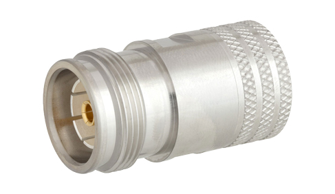
Low-power RF terminations function as matched loads designed to absorb RF energy and dissipate it as heat. They are engineered to match the characteristic impedance of the system, typically 50 ohms so that signals reaching the termination are fully absorbed rather than reflected. Internally, these terminations use precision resistive elements housed in a compact form factor, optimized for low power handling and wideband frequency performance. By eliminating reflections, low-power RF terminations help preserve clean signal behavior in RF and microwave circuits.
Common Use Cases for Low Power RF Terminations
Low-power RF terminations are widely used in test and measurement environments to terminate unused instrument ports and improve measurement accuracy. They are also essential in RF switches, directional couplers, and power dividers, where inactive ports must be properly terminated to prevent signal leakage. In modern communication systems, including MIMO and beamforming networks, low-power terminations ensure inactive signal paths do not degrade overall system performance. They are commonly used in laboratory setups, development platforms, and low-power RF signal chains.
Types of Low Power RF Terminations and Connectors
Low-power RF terminations are available in a variety of connector types to support different system interfaces and frequency ranges. Common connector options include SMA, SMB, SMC, SMP, SSMC, and N-type for lower frequencies, as well as precision connectors such as 3.5 mm, 2.92 mm (K-connector), 2.4 mm, and 1.85 mm for high-frequency and millimeter-wave applications. These terminations are offered in broadband and narrowband designs, with varying VSWR and frequency specifications to meet specific system requirements.
There are often occasions with RF signal chains where it is desirable to prevent the RF energy in that signal chain from either continuing along the signal chain or from exiting a given port. Given the nature of RF transmission lines, a simple short or open port will result in undesirable reflections and even signal emissions. Hence, it is often crucial to use RF Terminations to safely and securely absorb the excess signal energy while protecting other components in the signal chain from potentially harmful reflections that could cause interference or even damage. An example of this is when the transmission of a radar signal needs to abruptly stop by the time required to shut down the RF signal would take longer than the desired shut-off window. In this case, a switch can be placed in the transmission signal chain that redirects the output of the transmitter to a termination.
For legacy radars, the RF termination used in a radar application would need to be very high power. With the growing prevalence of smaller and more portable radar systems and communication systems, there is a growing need for Low-Power RF Terminations. A couple of factors are leading to this. With multi-input multi-output (MIMO) and beamforming technology there are typically many more signal paths feeding antenna elements than with previous radar and communication technologies that used a single higher power signal path. With a multitude of lower power signal paths, it is now possible to terminate these paths with low-power RF terminations. However, the higher number of signal paths also means that there needs to be a larger number of terminations available to terminate these ports.
Low power RF terminations are also extensively used with test and measurement applications. Many pieces of RF test equipment have exposed ports and benefit from having quality Coaxial Terminations at those ports. Moreover, there are many components and devices commonly used in RF tests that require RF terminations for some test setups, such as with directional couplers where only either the forward or reverse signal is needed.
As there is a plethora of various coaxial connector types, there are RF terminations made with each coaxial connector type. This includes push-connect type coaxial connectors, such as SSMC, SMP, SMC, SMB, etc.
With the growing interest in developing upper millimeter-wave technologies, there is a rising need for RF coaxial terminations that reach beyond 40 GHz. This is why 3.5 mm, 2.92 mm, 2.4 mm, and 1.85 mm are becoming increasingly available.
FAQs (Frequently Asked Questions)
1. What is an RF termination?
A: An RF termination is a matched load designed to absorb RF signals and prevent reflections in a transmission line. It typically matches the system's impedance (e.g., 50 Ω) to minimize signal distortion.
2. Are low-power RF terminations used?
A: They are used to terminate unused ports, switch paths, or test equipment interfaces in RF systems, ensuring that excess signal energy is absorbed rather than reflected into the system.
3. How do low power and high-power terminations differ?
A: Low power terminations handle lower wattage signals (often in the 1 W to 5 W range), while high power terminations are designed for much higher power levels and may include heat sinks or other cooling features.
4. Do low-power terminations come in different connector types?
A: Yes. They are available for a wide variety of coaxial connector interfaces, including SMB, SMC, SMP, and SSMC, and are also compatible with high-frequency connectors used above 40 GHz.
Related articles
Peter McNeil | Aug 02, 2022 | RF Terminations
RF terminations are one of the most common RF components used in nearly every application and use case where RF systems are employed. An RF termination is simply a terminating impedance that is designed to match the impedance of the transmission line or waveguide used in the signal chain. For instance, if a 50 Ohm coaxial path is to be properly terminated, say at the reverse port of a directional coupler, then the appropriate termination would be a 50 Ohm coaxial termination that matches the connector type of the directional coupler. Another example may be an extra test port that is generally unused but may be useful during maintenance or diagnostic troubleshooting. If unterminated the test port would return undesirable reflections and otherwise leak signals out of the open-ended port. An RF termination would safely prevent signal leakage and absorb the signal energy that would otherwise be reflected in an open port.

2.4mm RF Terminator
Another use case for an RF termination is if a transmit and receive signal chain are connected to an antenna via a switch as opposed to a diplexer or circulator. This is how many time domain duplex (TDD) and some radar operations. During a switching operation the transmitter signal energy would still be present for a short period of time. Hence, if the switch also changes the transmitter path to an RF termination with the appropriate ratings, the high-power RF from the transmitter can be safely terminated and absorbed. Otherwise potentially damaging reflections could occur as the input of an RF power amplifier or other transmission hardware has a limited reflected power handling capability.
RF terminations are also commonly used to terminate unused test ports in RF test and measurement equipment, such as a VNA. This is to prevent accidental reflections if a port is accidentally energized. If left open, the test port could cause damaging reflections to the sensitive test equipment receiver circuitry.
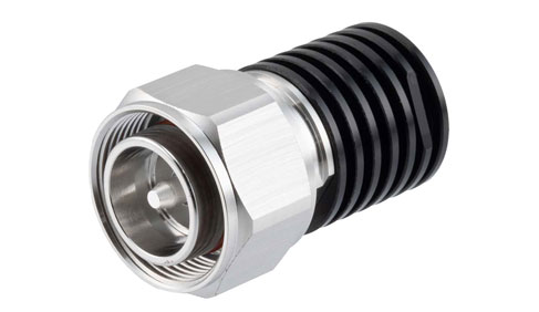
Given the various use cases of RF terminations, there are numerous types of RF terminations to better suit these use cases. For instance, there are some RF terminations meant for particularly high-power use cases. These RF terminations are generally larger in size and include a heat sink, often made from anodized aluminum. In more extreme high-power cases, an oil-filled terminator may be used, which uses oil to dissipate excess thermal energy. Some RF terminations even include active cooling systems for extremely high-power absorption.
However, many RF terminations are meant for lower power applications, such as those used with test and measurement equipment. These dummy loads are generally small and resemble an RF adapter. Some of these RF terminations may be multi-purpose and have two types of coaxial interface, one on either side. These are particularly useful in test and measurement applications where multiple coaxial connector types may be used in the same system.
Waveguide terminations are also common. Like with coaxial RF terminations, a waveguide termination may either be a simple length of waveguide with RF absorbing materials inside or include large heatsinks and even active cooling depending on the power rating of the termination.
Some RF terminations may also have other features, such as embedded O-rings for enhanced environmental performance, and clips/chains to ensure that a termination isn’t accidentally misplaced when temporarily removed.
