Key Takeaways
- High-performance PCB connectors (angled, vertical-launch, end-launch) enable compact RF and microwave designs by saving board space and allowing flexible signal routing, an essential feature when designing dense modules or high-speed backplanes.
- Advanced PCB connectors from Fairview Microwave support frequencies up to 67 GHz, making them suitable for modern high-frequency and millimeter-wave applications in telecommunications, aerospace, test & measurement, and defense.
- Properly chosen PCB connectors help maintain low VSWR, minimal insertion loss, and impedance matching key parameters for preserving RF signal integrity across PCBs, test fixtures, or communication modules.
- Using solderless, removable, or clamp-mount PCB connectors simplifies assembly, allows reuse, and reduces risk of damage, especially beneficial in prototype development, frequent test cycles, or modular setups.
Why PCB Connectors Are Critical for Modern RF / Microwave Designs
PCB connectors are essential building blocks in modern RF and microwave systems because they directly influence signal integrity, mechanical reliability, and overall device performance. As designs become smaller, faster, and more densely integrated, the need for precise and stable RF signal transitions from board to connector becomes even more important. PCB connectors provide a controlled 50-ohm interface, minimizing reflections and losses when routing high-frequency signals across communication modules, test equipment, radar boards, or 5G/mmWave circuitry. They also serve as an access point for measurements, assembly, tuning, and modular system upgrades.
Without high-performance PCB connectors, engineers would struggle to maintain consistent performance across miniaturized layouts, especially at frequencies extending into the microwave and millimeter-wave spectrum.
How to Select the Right PCB Connector for Your RF Application
Choosing the right PCB connector begins with evaluating the system’s frequency range, ensuring the connector meets or exceeds the maximum operating frequency with an adequate margin. Engineers should also consider connector style, angled, vertical, or end-launch—based on the mechanical layout, board design, and access requirements. Impedance stability, VSWR, and insertion loss must be reviewed to ensure the connector will not introduce unwanted reflections or signal degradation. Power-handling capability, mounting type (soldered vs. solderless), and mechanical durability also play a critical role in determining long-term reliability.
For prototype or lab environments, connectors that allow repeated installation and removal can significantly save time and cost. Ultimately, the best connector is one that balances electrical performance, mechanical suitability, cost, and ease of integration.
Common Mistakes and Pitfalls in PCB Connector Integration
A common issue engineers encounter is using a connector rated for lower frequencies in a system that operates at higher GHz ranges, leading to severe signal degradation and mismatch. Poor PCB layout around the launch area, improper ground vias, inconsistent trace impedance, or excessive pad size
can also introduce reflections and distortions. Neglecting mechanical stress considerations may result in connector lift-off, cracked solder joints, or micro-movements that disrupt high-frequency performance.
Another frequent mistake is selecting a connector solely based on size without evaluating its VSWR or insertion-loss characteristics. Failing to terminate unused ports or misaligning the connector with the RF trace can further contribute to instability, making the system difficult to calibrate and troubleshoot.
Designing high-performance RF systems often requires overcoming space limitations and optimizing signal routing with specialized components, such as angled PCB connectors. Unlike traditional straight connectors, PCB connectors allow for a more flexible orientation, making them ideal for compact designs where efficient use of space is crucial.
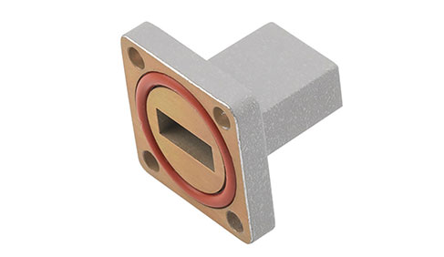
For example, when prototyping or working with tight spaces, the 1.85mm, female PCB mount vertical launch connector offers a clamp attachment design for easier installation. This product in particular supports up to 67 GHz performance, making it a reliable option for applications requiring high-frequency signal transmission.
Angled connectors like this one not only optimize space but also ensure that your system maintains low signal loss and high-frequency integrity, even when space is at a premium. Whether you're working on satellite communications, aerospace systems, or military radar systems, choosing the right connector can significantly enhance system performance.
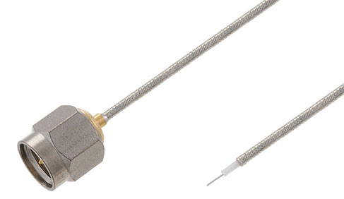
Similarly, for applications requiring high-frequency performance and easy integration, products like the 2.4mm Jack PCB Mount End Launch and the 2.4mm Jack Solderless PCB Mount offer solutions that streamline installation and improve overall system reliability. With 50 GHz performance and minimal signal loss, these connectors are designed to meet the rigorous demands of high-performance systems.
How to Choose the Right Printed Circuit Board Connectors for Your Application
Selecting the appropriate RF PCB connectors for your system requires careful consideration of several factors, including the frequency range, VSWR (Voltage Standing Wave Ratio), mounting options, and the available space in your design. Each of these factors plays a crucial role in ensuring the efficiency and performance of your RF system.
· Frequency Range: The frequency range is one of the most important factors when choosing a connector. RF connectors that support up to 50 GHz, are ideal for applications that demand high-frequency performance. It's essential to select connectors that match the frequency requirements of your system to avoid signal degradation and ensure the integrity of your data transmission.
· VSWR: VSWR is an important indicator of signal integrity. A low VSWR ensures minimal signal loss, meaning your system can transmit signals with high efficiency. When evaluating connectors, always check the VSWR specifications to ensure they meet the requirements of your application.
· Mounting Options: The mounting method of your connector can have a significant impact on the ease of installation and the overall design of your system. End-launch connectors are excellent for systems where space constraints require a compact and efficient connector without sacrificing performance.
· Available Space: The physical space available in your design is another critical factor to consider. For systems with tight space requirements, narrow-body connectors high performance while occupying minimal space. These types of connectors are ideal for applications in military defense or satellite communications, where every inch of space matters.
Optimizing System Performance with the Right Connectors
Choosing the right connector can dramatically impact the performance of your RF system. For industries such as military defense, satellite communications, and RF testing, where precision is critical, high-performance connectors are a must.
These connectors also provide flexibility in routing and space-saving benefits that are essential in modern RF designs. Whether you need angled connectors for tight spaces or end-launch connectors for ease of integration, the right product ensures your system will operate at its best.
Future-Proof Your RF Designs with Top-Quality Printed Circuit Board Connectors
When designing your next high-performance RF system, consider the impact that these connectors and end launch connectors can have on your system’s performance. The connectors discussed here offer high-frequency performance, low-loss transmission, and the versatility required for demanding applications. Whether you’re working in telecommunications, military defense, or test & measurement, choosing the right connector ensures your system operates efficiently, even in tight spaces.
Our PCB connectors provide optimal signal integrity, reduced installation time, and ensure your systems perform at their best. Explore our range of high-performance RF PCB connectors today and get the reliability you need for your next big project.
Frequently Asked Questions (FAQ)
Q1: What makes a PCB connector different from a standard coaxial or cable connector?
A: A PCB connector is specifically designed to launch an RF signal directly from or to a printed circuit board (PCB), maintaining impedance integrity, minimizing reflections, and preserving signal quality unlike standard coaxial cable connectors which are geared toward cable-to-cable or cable-to-device connections.
Q2: What types of PCB connectors are commonly used in RF/microwave design?
A: Common types include angled PCB-mount launch connectors, vertical-launch (solderless) connectors, and end-launch / edge-launch connectors. Each type serves different layout needs and space constraints.
Q3: Up to what frequency can PCB connectors reliably operate?
A: High-quality PCB connectors from leading manufacturers can operate up to millimeter-wave frequencies for example, some angled or vertical launch PCB connectors support operation up to 67 GHz.