
What Makes an RF Coupler Fit for Defense Applications?
Key Takeaways
- Defense-grade RF couplers must handle extreme environmental stresses including shock, vibration, humidity, altitude/pressure variations, corrosion, and wide temperature swing conditions often far beyond typical commercial applications.
- High power handling capability is critical: couplers used in radar, satellite communications, or high-power transmit paths may need to manage hundreds to thousands of watts, both CW and pulsed, without performance degradation.
- Wide frequency bandwidth is often a requirement for defense systems that may operate across C-band, X-band, Ku-band or beyond, so a coupler must maintain coupling consistency, isolation, and VSWR over a broad spectrum.
- Materials and construction must meet or exceed military specifications (MIL-spec) for plating, connectors, sealing, and mechanical joints, for example, corrosion-resistant plating to prevent degradation in marine or high-humidity environments.
- Proper coupling quality means high directivity and isolation, minimizing signal leakage, or reflection. This is vital for accurate signal sampling, monitoring, or measurement in defense communication and radar systems.
Why Standard RF Couplers Often Fall Short in Defense & Aerospace Usage
Standard commercial RF couplers are designed for controlled environments such as labs, indoor communication setups, and general-purpose RF testing. Defense and aerospace applications, however, operate in conditions far more demanding than what these components are typically rated for. High vibration levels, extreme temperatures, rapid pressure changes, shock loads, and long-term exposure to humidity or corrosive elements can quickly degrade a commercial-grade coupler.
Additionally, military communication, radar, and EW (Electronic Warfare) systems require exceptional stability and accuracy over wide frequency ranges. Commercial couplers often exhibit performance drift under thermal stress, limited power handling capability, and inconsistent coupling values outside their nominal specifications. These limitations can impair signal sampling, degrade system performance, and compromise mission-critical reliability making standard couplers unsuitable for defense-grade deployments.
Coupler Types for Defense Applications: Waveguide vs Coaxial vs Directional
Defense systems rely on a variety of coupler technologies based on power levels, frequency bands, and environmental constraints:
Waveguide Couplers
Waveguide couplers are commonly used in radar, airborne systems, and high-power microwave applications. Their inherently low loss and high-power handling make them ideal for X-band, Ku-band, and Ka-band systems. They also offer excellent environmental resistance due to their rugged metallic structure.
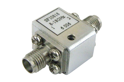
Coaxial Couplers
Coaxial couplers are chosen when systems require compact size, moderate power handling, or compatibility with existing coaxial architectures. For defense environments, they must feature reinforced bodies, corrosion-resistant plating, hermetic or weatherproof sealing, and MIL-spec connectors to survive harsh climates and shock/vibration loads.
Directional Couplers
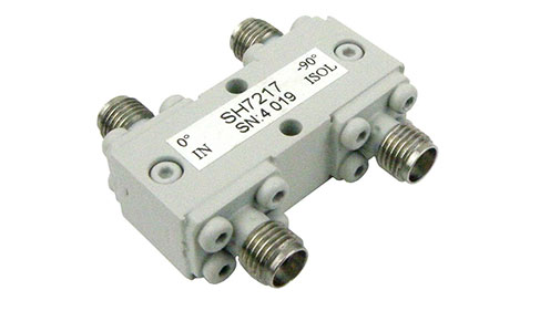
Directional couplers provide accurate sampling of forward or reverse power and are essential in radar calibration, VSWR monitoring, jamming systems, and antenna performance verification. In defense applications, they require high directivity, stable coupling factors across wide bandwidths, and ruggedized construction to maintain measurement accuracy even under thermal or mechanical stress.
There are many instances in military/defense, aerospace, space, and naval applications where there is a need for sampling signals from high power transmission paths or monitoring the frequency of high-power signal paths. In these cases, the best RF component for the job is often an RF coupler. However, not all RF couplers are designed for extreme environmental applications indicative of the requirements for defense applications.
For instance, many RF couplers have coaxial connector ports either for the primary signal paths or the coupled ports. If the coaxial connector ports are coaxial types that use dielectric spacers, it may be that the dielectric material used can’t sufficiently perform under extreme temperature ranges specified for military grade coaxial connectors. Other environmental features include corrosion resistance, shock, vibration, humidity, altitude/pressure, etc.
Generally, standard waveguide flanges can meet all of these requirements, possibly with the exception of corrosion resistance. This is why many waveguides meant for defense applications are gold plated; this helps prevent corrosion while still maintaining high conductivity for low loss performance. A common standard for body plating specifications for waveguide couplers is MIL-DTL-5541.
Even with waveguide couplers, if the attachment methods of the coupled ports aren’t designed to withstand shock and vibration, the joint between the main waveguide and coupled waveguide may degrade or even fail. Hence, it is often imperative to ensure that even waveguide couplers are designed to meet MIL-Spec standards for ruggedness. For altitude/pressure performance, couplers often need to be sealed, either hermetically or with epoxy, to prevent outgassing or debris ingress to meet defense standards.
RF couplers designed for defense applications also tend to be specified to operate over certain useful frequency ranges and power levels for defense use cases. Examples of this include RF directional waveguide couplers designed to operate from 100s to 1000s of Watts and in key radar frequency bands, such as C-band, X-band, Ku-band, etc. These couplers will often have high peak and continuous wave (CW) input power ranges specified, as radar applications tend to have high peak power outputs.
All of these factors considered together likely indicate that a RF coupler has been designed to meet defense applications, even if it is not explicitly identified as such.
Recommendations
For defense and aerospace RF systems, selecting the right coupler requires a strategy that balances electrical performance, ruggedness, and long-term reliability. Engineers should always choose MIL-spec–qualified waveguide or coaxial couplers when operating in high-power or mission-critical environments, as these units are designed to withstand harsh thermal, mechanical, and environmental stress. It’s also recommended to prioritize couplers with high directivity and stable coupling values across wide frequency bands to ensure accurate signal sampling and system diagnostics.
When integrating into airborne, naval, or mobile platforms, opt for models with hermetic sealing, corrosion-resistant plating, and vibration-rated construction to prevent moisture ingress and mechanical fatigue. For systems that involve pulsed radars or EW transmitters, selecting couplers with robust peak power handling and low insertion loss is essential to avoid electrical breakdown. Finally, engineers should perform regular calibration checks and preventive maintenance on couplers to monitor drift, verify connector integrity, and ensure system readiness under demanding operational conditions.