
RF Power Divider & Power Splitter Differences & Applications
Key Takeaways
- Power dividers and power splitters both divide RF energy, but dividers are often reciprocal and may support bidirectional signal flow.
- Wilkinson dividers provide good isolation and phase balance, ideal for phased arrays and measurement systems.
- Resistive splitters are low-cost and simple but offer higher loss and lower isolation.
- Applications span test setups, DAS, antenna systems, mixers, and RF front ends.
- Performance considerations include phase balance, insertion loss, isolation, frequency range, and power handling.
What Is an RF Power Divider?
An RF power divider is a passive microwave component designed to split an input RF signal into two or more output signals with controlled amplitude and phase characteristics. Power dividers are typically reciprocal devices, meaning they can also function in reverse to combine multiple input signals into a single output. They are engineered to maintain impedance matching at all ports, usually 50 ohms, while minimizing insertion loss and ensuring consistent signal distribution. Because of their balanced performance and isolation features, RF power dividers are commonly used in phased array antennas, test and measurement systems, and local oscillator distribution networks.
What Is an RF Power Splitter?
An RF power splitter is a passive device used to divide an RF signal into multiple outputs, primarily for one-directional signal distribution. Unlike power dividers, power splitters are often optimized for simplicity and cost-effectiveness rather than bidirectional operation or port isolation. They are widely used in broadcast, distributed antenna systems (DAS), and basic RF signal routing applications where precise phase balance or signal combining is not required. While power splitters perform a similar function to power dividers, they may exhibit higher insertion loss and lower isolation between output ports.
How RF Power Dividers and Power Splitters Work
RF power dividers and power splitters operate by dividing the electromagnetic energy of an input signal across multiple transmission paths within the device. This division is achieved using resistive networks, transmission-line structures, or hybrid coupler designs, depending on the type of device. In power dividers such as Wilkinson designs, internal resistors provide isolation between output ports, preventing signal interaction, and maintaining phase balance. Power splitters, on the other hand, often rely on simpler resistive or transmission-line layouts, which distribute power effectively but with less isolation. In both cases, careful impedance matching is essential to minimize reflections and preserve signal integrity.
Key Differences Between RF Power Dividers and Power Splitters
The primary difference between RF power dividers and power splitters lies in their functionality and performance characteristics. Power dividers are generally reciprocal, offering bidirectional operation with controlled phase balance and isolation between output ports. This makes them suitable for precision RF systems and signal combining applications. Power splitters, by contrast, are typically non-reciprocal or optimized for unidirectional use, with simpler designs and fewer performance guarantees. As a result, power splitters are more commonly used in cost-sensitive or distribution-focused applications, while power dividers are preferred in high-performance RF and microwave systems requiring accuracy and repeatability.
There are many circumstances in RF applications where there is a need to redirect a signal into two or more separate ports simultaneously. There are a few different components capable of this, but two of the most common are RF power dividers/combiners and power splitters. Power dividers/splitters are often considered the same category of components, though some consider there to be a divide in the construction and use case of these components.
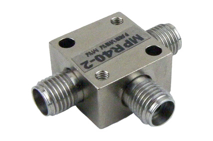
One definition of a power divider is a component with 3 or more ports where each port presents an equivalent characteristic impedance at each port and the “output” ports exhibit a uniform division of energy from the “input” port. In this case, a power divider provides a good impedance match amongst all of the ports, including a source match. Hence, a power divider can be used for highly accurate comparison measurements . For instance, it may be needed to split a signal between two or more different measurement apparatus, such as frequency, power, phase, distortion, or other signal characteristics. Power dividers defined in this way are also intrinsically bi-directional and can also be used as power combiners. The equivalent circuit for this device is a multi-resistor network where each port of the power divider/combiner network has a necessary resistance to have an equivalent port impedance that matches with the characteristic impedance of the transmission line impedance.
A power splitter, on the other hand, can be defined in the simplest terms as a two-resistor network (this could be an equivalent circuit). In this design the “input” port of the equivalent circuit is without a resistor and the “output” ports have a two-resistor configuration that results in an input impedance that matches the characteristic impedance of the transmission lines. This minimizes uncertainty in source leveling or ratio measurements with good output match to RF sources.
Power Splitters are often used for gain compression, power, and gain testing. A source signal is sent to a power splitter that drives both a DUT followed by a detector and a detector without the DUT. Analyzing the signals from the split signals provides an accurate comparison of the signals and removes the re-reflected signals allowing for repeated gain measurements at different RF power levels without recalibration.
Power dividers can be used for any occasion where a signal needs to be evenly split or combined into any number of ports, such as an 8-way RF power divider. This includes intermodulation distortion (IMD), diversity gain, multi-element antenna arrays etc.
FAQs (Frequently Asked Questions)
Q1: What is the main difference between a power divider and a power splitter?
A: A power divider is designed as a reciprocal network that can split or combine signals with controlled amplitude and phase, whereas a power splitter is often used only in a single direction for signal distribution without bidirectional expectations.
Q2: What is a Wilkinson power divider?
A: A Wilkinson divider is a type of power divider with resistive isolation between output ports, providing good phase balance and output isolation with low VSWR.
Q3: Can a power divider also combine signals?
A: Yes, many power dividers are reciprocal networks and can combine signals from multiple inputs into one output with proper matching.