
How Do RF Frequency Synthesizers Work?
Most RF applications require, or benefit, from a highly accurate and stable frequency source. One of the most common ways of generating such a source is using RF Frequency Synthesizers. There are many types of RF frequency synthesizers, but the basic premise for these devices is that they use an oscillator reference frequency and a feedback network that results in a stable high frequency source. There are types of frequency synthesizers, direct synthesizers, that don’t use any type of frequency translation element and directly generate the synthesized waveform. This is either done using an analog source or via direct digital synthesis (DDS). The analog frequency synthesizer approach is used in some modern applications but is generally not as compatible with the requirements of the latest wireless communications, sensing, and imaging technologies. As direct digital synthesis devices become more common and lower cost, these devices are increasingly being used as they can help realize software-defined RF systems that are both compact, efficient, and flexible. The cost and complexity of implementing DDS is a limiting factor in many applications, and there are many common indirect frequency synthesis technologies with relatively inexpensive or high-performance modules that are readily available as commercial-off-the-shelf (COTS) or team’s that can design and manufacture custom devices.
Key Takeaways
A frequency synthesizer enables generation of multiple output frequencies from a single reference frequency by using oscillators, PLLs, dividers, and mixers.
The PLL architecture is common: the output of a tunable VCO (voltage-controlled oscillator) is locked in phase and/or frequency to a lower-frequency reference, forcing stability and control
There are major trade-offs: frequency resolution, switching speed, phase noise, and spur-level performance. All must be balanced depending on the application.
The choice between Integer-N, Fractional-N, and DDS approaches affects cost, complexity, performance, tuning range, and agility.
In RF and microwave systems (communications, radar, test gear), the synthesizer’s performance (clean output, low phase noise, fast switching) can be a limiting factor on system sensitivity and dynamic range.
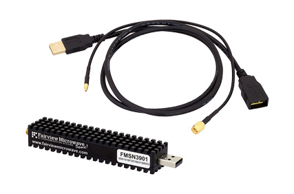
The basic components of an indirect type of frequency synthesizer, such as phase locked loop (PLL), are the reference, a phase detector, a frequency divider (programmable fractional n-divider for instance), a voltage-controlled oscillator (VCO), and a feedback filter (often a loop filter). The idea is that the output signal of the VCO is divided down in frequency to the order of the reference frequency and the difference is fed to the loop filter that corrects the VCO’s output. If the phase detector and reference operate at the same frequency range as the VCO, then a frequency divider is not needed. The frequency divider can be analog or digital, which is the main differentiator between an analog or digital frequency synthesizer. An example of a digital and digitally controllable frequency synthesizer is a USB Controlled PLL Frequency Synthesizers.
Recommendations
When selecting a synthesizer, specify your required output frequency range, step size (resolution), spurious/phase-noise budget, and switch speed upfront.
Ensure your system’s reference clock is stable and low noise (e.g., TCXO or OCXO) since its quality directly affects synthesizer output purity.
If your application demands fine frequency steps with low phase noise (e.g., instrumentation), favor Fractional-N (or DDS) designs—but be aware of added complexity and potential spurs.
For simpler applications where frequency steps are coarser, Integer-N PLLs may suffice and offer lower cost and simpler design.
Always review the phase noise plot and spur chart of the synthesizer under the actual conditions (frequency, temperature, tuning) you expect in your system.
In modular systems or test equipment, check for features like switching speed, frequency hopping capability, and programmability that match your workflow.
By adjusting the ratio of the frequency divider, it is possible to control the output frequency of the VCO. If the synthesizer is being used in a channelized communications system, the comparison frequency/reference frequency is generally chosen to be equal to the channel spacing, which eases the complexity of the design and simplifies the RF circuit for some applications, such as FM radio.