Due to severe weather conditions across the country, some orders may be slightly delayed. If you have any questions about your order, please contact us at +1 (866) 316-4681
Same-day shipping if you order in the next
Need assistance? +1 (800) 715-4396
400/403 Bad Request
The requested page could not be found.
The requested page could not be found.
500 Internal Server Error
Oops, something went wrong.
#Internal server error, refresh the page or contact us if the problem persists.
Oops, something went wrong.
#Internal server error, refresh the page or contact us if the problem persists.
[{"category":{"categoryId":"3d574e8a-e24d-432d-b9dd-92920f6f5b78","name":"Antenna Accessories","seoName":"antenna-accessories","categoryPath":"Antenna Accessories","categorySeoUrl":"antenna-accessories","childCategories":[{"categoryId":"2c0e0201-2551-4aa8-8456-58b74bca8129","name":"Antenna Covers","seoName":"antenna-covers","categoryPath":"Antenna Accessories|Antenna Covers","categorySeoUrl":"antenna-accessories|antenna-covers","childCategories":[{"categoryId":"d8d4b302-4af8-4e94-8295-070ff33b3523","name":"Waveguide Horn Antenna Covers","seoName":"waveguide-horn-antenna-covers","categoryPath":"Antenna Accessories|Antenna Covers|Waveguide Horn Antenna Covers","categorySeoUrl":"antenna-accessories|antenna-covers|waveguide-horn-antenna-covers","childCategories":null}]},{"categoryId":"1f9cfc4c-a557-40f0-aebb-9b41b2a3cfd3","name":"Antenna Mounts","seoName":"antenna-mounts","categoryPath":"Antenna Accessories|Antenna Mounts","categorySeoUrl":"antenna-accessories|antenna-mounts","childCategories":[{"categoryId":"8dc3333d-7ff5-474a-a80e-9d686ec2832d","name":"Antenna Roof Mounts","seoName":"antenna-roof-mounts","categoryPath":"Antenna Accessories|Antenna Mounts|Antenna Roof Mounts","categorySeoUrl":"antenna-accessories|antenna-mounts|antenna-roof-mounts","childCategories":null},{"categoryId":"fe937035-2fef-42bd-b505-bb088ca023a9","name":"Magnetic NMO Antenna Mounts","seoName":"magnetic-nmo-antenna-mounts","categoryPath":"Antenna Accessories|Antenna Mounts|Magnetic NMO Antenna Mounts","categorySeoUrl":"antenna-accessories|antenna-mounts|magnetic-nmo-antenna-mounts","childCategories":null},{"categoryId":"016d2a5e-ef96-4943-b19b-a0752ab72714","name":"Marine Antenna Mounts","seoName":"marine-antenna-mounts","categoryPath":"Antenna Accessories|Antenna Mounts|Marine Antenna Mounts","categorySeoUrl":"antenna-accessories|antenna-mounts|marine-antenna-mounts","childCategories":null},{"categoryId":"df9907dc-8311-4a6d-93e4-879ac9ff0910","name":"Spring Barrel Mounts","seoName":"spring-barrel-mounts","categoryPath":"Antenna Accessories|Antenna Mounts|Spring Barrel Mounts","categorySeoUrl":"antenna-accessories|antenna-mounts|spring-barrel-mounts","childCategories":null},{"categoryId":"2f39f216-a11c-42a5-bec8-65f9415387da","name":"Waveguide Horn Antenna Mounts","seoName":"waveguide-horn-antenna-mounts","categoryPath":"Antenna Accessories|Antenna Mounts|Waveguide Horn Antenna Mounts","categorySeoUrl":"antenna-accessories|antenna-mounts|waveguide-horn-antenna-mounts","childCategories":null}]},{"categoryId":"3378d97a-03b7-4f21-a015-d2f14827be09","name":"Antenna Poles","seoName":"antenna-poles","categoryPath":"Antenna Accessories|Antenna Poles","categorySeoUrl":"antenna-accessories|antenna-poles","childCategories":[{"categoryId":"e2460876-2abc-4aaf-8f05-88dca30a7ce9","name":"Flat Roof Mount Poles","seoName":"flat-roof-mount-poles","categoryPath":"Antenna Accessories|Antenna Poles|Flat Roof Mount Poles","categorySeoUrl":"antenna-accessories|antenna-poles|flat-roof-mount-poles","childCategories":null},{"categoryId":"9856ff8e-ef4b-4df0-9cd5-d98a3b49db68","name":"Peak Roof Mount Poles","seoName":"peak-roof-mount-poles","categoryPath":"Antenna Accessories|Antenna Poles|Peak Roof Mount Poles","categorySeoUrl":"antenna-accessories|antenna-poles|peak-roof-mount-poles","childCategories":null}]}]}},{"category":{"categoryId":"c281ddfd-2fbe-4f81-8864-66d0bcc0ec74","name":"Antennas","seoName":"antennas","categoryPath":"Antennas","categorySeoUrl":"antennas","childCategories":[{"categoryId":"5c0d0229-d332-4241-98b5-d17db27baa5d","name":"Directional Antennas","seoName":"directional-antennas","categoryPath":"Antennas|Directional Antennas","categorySeoUrl":"antennas|directional-antennas","childCategories":[{"categoryId":"48fc5314-61c2-4cb1-a5f2-e611cadfc86f","name":"Log Periodic Antennas","seoName":"log-periodic-antennas","categoryPath":"Antennas|Directional Antennas|Log Periodic Antennas","categorySeoUrl":"antennas|directional-antennas|log-periodic-antennas","childCategories":null},{"categoryId":"62615a8b-4022-43e5-9efb-6d1a1dd0cc38","name":"Panel Antennas","seoName":"panel-antennas","categoryPath":"Antennas|Directional Antennas|Panel Antennas","categorySeoUrl":"antennas|directional-antennas|panel-antennas","childCategories":null},{"categoryId":"f7425611-ec89-406e-aaf9-469cb77a3bc5","name":"Parabolic Antennas","seoName":"parabolic-antennas","categoryPath":"Antennas|Directional Antennas|Parabolic Antennas","categorySeoUrl":"antennas|directional-antennas|parabolic-antennas","childCategories":null},{"categoryId":"85a36a95-09d1-4eaf-bc5d-42efe4a3185e","name":"Patch Antennas","seoName":"patch-antennas","categoryPath":"Antennas|Directional Antennas|Patch Antennas","categorySeoUrl":"antennas|directional-antennas|patch-antennas","childCategories":null},{"categoryId":"f43e6504-98ee-4b3a-8d32-aeae3198a30a","name":"Waveguide Antennas Directional","seoName":"waveguide-antennas-directional","categoryPath":"Antennas|Directional Antennas|Waveguide Antennas Directional","categorySeoUrl":"antennas|directional-antennas|waveguide-antennas-directional","childCategories":null},{"categoryId":"8e5bfa95-2aa3-40ee-9c04-1cc8e12b51e8","name":"Yagi Antennas","seoName":"yagi-antennas","categoryPath":"Antennas|Directional Antennas|Yagi Antennas","categorySeoUrl":"antennas|directional-antennas|yagi-antennas","childCategories":null}]},{"categoryId":"d6d487bc-0a19-40e0-bec9-425828df5701","name":"Omni-Directional Antennas","seoName":"omni-directional-antennas","categoryPath":"Antennas|Omni-Directional Antennas","categorySeoUrl":"antennas|omni-directional-antennas","childCategories":[{"categoryId":"18ca1aef-9bbd-46e4-9c92-23c82f6d70ba","name":"Ceiling Antennas","seoName":"ceiling-antennas","categoryPath":"Antennas|Omni-Directional Antennas|Ceiling Antennas","categorySeoUrl":"antennas|omni-directional-antennas|ceiling-antennas","childCategories":null},{"categoryId":"f5c2d693-6788-43e5-bffd-75e8aa78dfd6","name":"Collinear Antennas","seoName":"collinear-antennas","categoryPath":"Antennas|Omni-Directional Antennas|Collinear Antennas","categorySeoUrl":"antennas|omni-directional-antennas|collinear-antennas","childCategories":null},{"categoryId":"0ecb060b-c53e-4052-971c-4e57123c5be4","name":"Dipole Antennas","seoName":"dipole-antennas","categoryPath":"Antennas|Omni-Directional Antennas|Dipole Antennas","categorySeoUrl":"antennas|omni-directional-antennas|dipole-antennas","childCategories":null},{"categoryId":"62b5647a-a726-4fc5-98b7-77dcb39fc8f4","name":"Embedded Antennas","seoName":"embedded-antennas","categoryPath":"Antennas|Omni-Directional Antennas|Embedded Antennas","categorySeoUrl":"antennas|omni-directional-antennas|embedded-antennas","childCategories":null},{"categoryId":"21c5f383-856c-48dc-9457-e80ec826d4b1","name":"Fixed Antennas","seoName":"fixed-antennas","categoryPath":"Antennas|Omni-Directional Antennas|Fixed Antennas","categorySeoUrl":"antennas|omni-directional-antennas|fixed-antennas","childCategories":null},{"categoryId":"25a662a2-4868-4ca2-9b91-c2dc179759e3","name":"GPS / GNSS / GLNSS /GLONSS Antennas","seoName":"gps-gnss-glnss-glonss-antennas","categoryPath":"Antennas|Omni-Directional Antennas|GPS / GNSS / GLNSS /GLONSS Antennas","categorySeoUrl":"antennas|omni-directional-antennas|gps-gnss-glnss-glonss-antennas","childCategories":null},{"categoryId":"c8ab274b-2056-4e5c-80f5-132bd6f7fd16","name":"Gooseneck Antennas","seoName":"gooseneck-antennas","categoryPath":"Antennas|Omni-Directional Antennas|Gooseneck Antennas","categorySeoUrl":"antennas|omni-directional-antennas|gooseneck-antennas","childCategories":null},{"categoryId":"74abc632-fa61-48ed-acf1-41ba1b746381","name":"Military Antennas","seoName":"military-antennas","categoryPath":"Antennas|Omni-Directional Antennas|Military Antennas","categorySeoUrl":"antennas|omni-directional-antennas|military-antennas","childCategories":null},{"categoryId":"d1a4787e-e911-4db2-a8c5-53506c7f71de","name":"Mini Antennas","seoName":"mini-antennas","categoryPath":"Antennas|Omni-Directional Antennas|Mini Antennas","categorySeoUrl":"antennas|omni-directional-antennas|mini-antennas","childCategories":null},{"categoryId":"a8bd3564-e908-44d1-a0fa-4341db818dcc","name":"Mobile Antennas","seoName":"mobile-antennas","categoryPath":"Antennas|Omni-Directional Antennas|Mobile Antennas","categorySeoUrl":"antennas|omni-directional-antennas|mobile-antennas","childCategories":null},{"categoryId":"cb01cd01-0b1e-4ca4-a762-06703543f0f3","name":"Omni Antennas","seoName":"omni-antennas","categoryPath":"Antennas|Omni-Directional Antennas|Omni Antennas","categorySeoUrl":"antennas|omni-directional-antennas|omni-antennas","childCategories":null},{"categoryId":"4ce26ab4-3825-4de1-8435-feb7a9062518","name":"Paddle Antennas","seoName":"paddle-antennas","categoryPath":"Antennas|Omni-Directional Antennas|Paddle Antennas","categorySeoUrl":"antennas|omni-directional-antennas|paddle-antennas","childCategories":null},{"categoryId":"5d39c3ce-aea8-44a5-825d-cd7dd713d64f","name":"Portable Antennas","seoName":"portable-antennas","categoryPath":"Antennas|Omni-Directional Antennas|Portable Antennas","categorySeoUrl":"antennas|omni-directional-antennas|portable-antennas","childCategories":null},{"categoryId":"bf37e9ac-8743-4615-9b17-62bd25d118a3","name":"Rubber Duck Antennas","seoName":"rubber-duck-antennas","categoryPath":"Antennas|Omni-Directional Antennas|Rubber Duck Antennas","categorySeoUrl":"antennas|omni-directional-antennas|rubber-duck-antennas","childCategories":null},{"categoryId":"172a85d7-fe45-48cf-a4dd-31d258128f47","name":"Waveguide Omni Antennas","seoName":"waveguide-omni-antennas","categoryPath":"Antennas|Omni-Directional Antennas|Waveguide Omni Antennas","categorySeoUrl":"antennas|omni-directional-antennas|waveguide-omni-antennas","childCategories":null},{"categoryId":"235da3a9-4362-4d51-95de-aceb8284fb7e","name":"Whip Antennas","seoName":"whip-antennas","categoryPath":"Antennas|Omni-Directional Antennas|Whip Antennas","categorySeoUrl":"antennas|omni-directional-antennas|whip-antennas","childCategories":null}]},{"categoryId":"4df01ced-a4f0-468e-ab05-5dcd031dfcf6","name":"Upgrade Kits for Antennas","seoName":"upgrade-kits-for-antennas","categoryPath":"Antennas|Upgrade Kits for Antennas","categorySeoUrl":"antennas|upgrade-kits-for-antennas","childCategories":[{"categoryId":"9f376adc-b960-42b2-8be5-b0768216e210","name":"Helium Miner Upgrade Kits for Antennas","seoName":"helium-miner-upgrade-kits-for-antennas","categoryPath":"Antennas|Upgrade Kits for Antennas|Helium Miner Upgrade Kits for Antennas","categorySeoUrl":"antennas|upgrade-kits-for-antennas|helium-miner-upgrade-kits-for-antennas","childCategories":null}]}]}},{"category":{"categoryId":"a6271af0-5469-4d87-b28d-1e529ff52fc3","name":"Bi-Phase RF Modulators","seoName":"bi-phase-rf-modulators","categoryPath":"Bi-Phase RF Modulators","categorySeoUrl":"bi-phase-rf-modulators","childCategories":[{"categoryId":"d98b5c03-d1d0-462e-8bcd-2ffe2308cd0c","name":"SMA Bi-Phase Modulators","seoName":"sma-bi-phase-modulators","categoryPath":"Bi-Phase RF Modulators|SMA Bi-Phase Modulators","categorySeoUrl":"bi-phase-rf-modulators|sma-bi-phase-modulators","childCategories":[{"categoryId":"9bb25a3b-5ba9-4a97-9971-28966b74568f","name":"0/180 Degree SMA Bi-Phase Modulators","seoName":"0-180-degree-sma-bi-phase-modulators","categoryPath":"Bi-Phase RF Modulators|SMA Bi-Phase Modulators|0/180 Degree SMA Bi-Phase Modulators","categorySeoUrl":"bi-phase-rf-modulators|sma-bi-phase-modulators|0-180-degree-sma-bi-phase-modulators","childCategories":null}]}]}},{"category":{"categoryId":"61dc9209-6334-4df0-83ee-9269047b9d49","name":"Cable Assembly Accessories","seoName":"cable-assembly-accessories","categoryPath":"Cable Assembly Accessories","categorySeoUrl":"cable-assembly-accessories","childCategories":[{"categoryId":"618e0a5d-7915-4b0e-8786-9c30d23452ca","name":"Weatherproof Boots","seoName":"weatherproof-boots","categoryPath":"Cable Assembly Accessories|Weatherproof Boots","categorySeoUrl":"cable-assembly-accessories|weatherproof-boots","childCategories":[{"categoryId":"a0d071c6-9a29-4fb5-af0b-a076feca98c3","name":"2.2-5/TNC Weatherproof Boots","seoName":"2.2-5-tnc-weatherproof-boots","categoryPath":"Cable Assembly Accessories|Weatherproof Boots|2.2-5/TNC Weatherproof Boots","categorySeoUrl":"cable-assembly-accessories|weatherproof-boots|2.2-5-tnc-weatherproof-boots","childCategories":null},{"categoryId":"b697f487-1785-4dbf-bec7-b7d141360256","name":"SMA Weatherproof Boots","seoName":"sma-weatherproof-boots","categoryPath":"Cable Assembly Accessories|Weatherproof Boots|SMA Weatherproof Boots","categorySeoUrl":"cable-assembly-accessories|weatherproof-boots|sma-weatherproof-boots","childCategories":null},{"categoryId":"1e2e9e10-e835-46f9-828c-2fb8263868dc","name":"Type N Weatherproof Boots","seoName":"type-n-weatherproof-boots","categoryPath":"Cable Assembly Accessories|Weatherproof Boots|Type N Weatherproof Boots","categorySeoUrl":"cable-assembly-accessories|weatherproof-boots|type-n-weatherproof-boots","childCategories":null}]}]}},{"category":{"categoryId":"47a23a80-61c4-4ae3-bc27-b6d8190369af","name":"Interconnect Miscellaneous","seoName":"interconnect-miscellaneous","categoryPath":"Interconnect Miscellaneous","categorySeoUrl":"interconnect-miscellaneous","childCategories":[{"categoryId":"7580c97c-a3a7-4eb6-8b71-bd6c593df73d","name":"D-Subminiature","seoName":"d-subminiature","categoryPath":"Interconnect Miscellaneous|D-Subminiature","categorySeoUrl":"interconnect-miscellaneous|d-subminiature","childCategories":[{"categoryId":"cd16c900-0767-4b1b-b11e-79c9e74102ea","name":"Accessories","seoName":"accessories","categoryPath":"Interconnect Miscellaneous|D-Subminiature|Accessories","categorySeoUrl":"interconnect-miscellaneous|d-subminiature|accessories","childCategories":null}]}]}},{"category":{"categoryId":"79eda58d-d9d4-4b64-8660-344074ab3afa","name":"MIL-STD Cable Assemblies","seoName":"mil-std-cable-assemblies","categoryPath":"MIL-STD Cable Assemblies","categorySeoUrl":"mil-std-cable-assemblies","childCategories":[{"categoryId":"a89616c6-d81e-4b63-8641-712d2db475b6","name":"MIL-STD-1553B","seoName":"mil-std-1553b","categoryPath":"MIL-STD Cable Assemblies|MIL-STD-1553B","categorySeoUrl":"mil-std-cable-assemblies|mil-std-1553b","childCategories":[{"categoryId":"c2987840-9b1e-4763-9773-fa3ee507ea98","name":"Blunt Cut Cable Assemblies","seoName":"blunt-cut-cable-assemblies","categoryPath":"MIL-STD Cable Assemblies|MIL-STD-1553B|Blunt Cut Cable Assemblies","categorySeoUrl":"mil-std-cable-assemblies|mil-std-1553b|blunt-cut-cable-assemblies","childCategories":null},{"categoryId":"d05a8043-41c6-4a39-b042-c6786464d105","name":"TRB (Bayonet) Cable Assemblies","seoName":"trb-bayonet-cable-assemblies","categoryPath":"MIL-STD Cable Assemblies|MIL-STD-1553B|TRB (Bayonet) Cable Assemblies","categorySeoUrl":"mil-std-cable-assemblies|mil-std-1553b|trb-bayonet-cable-assemblies","childCategories":null},{"categoryId":"500b1ad0-3df6-49cb-a720-1e35160bdacd","name":"TRS (Threaded Subminiature) Cable Assemblies","seoName":"trs-threaded-subminiature-cable-assemblies","categoryPath":"MIL-STD Cable Assemblies|MIL-STD-1553B|TRS (Threaded Subminiature) Cable Assemblies","categorySeoUrl":"mil-std-cable-assemblies|mil-std-1553b|trs-threaded-subminiature-cable-assemblies","childCategories":null},{"categoryId":"b51d99ce-1336-42e8-9b91-4f251c2ce3e0","name":"TRT (Threaded) Cable Assemblies","seoName":"trt-threaded-cable-assemblies","categoryPath":"MIL-STD Cable Assemblies|MIL-STD-1553B|TRT (Threaded) Cable Assemblies","categorySeoUrl":"mil-std-cable-assemblies|mil-std-1553b|trt-threaded-cable-assemblies","childCategories":null}]}]}},{"category":{"categoryId":"c5dae7d6-7fe0-46be-89a7-14ae41721b87","name":"Magic Tees","seoName":"magic-tees","categoryPath":"Magic Tees","categorySeoUrl":"magic-tees","childCategories":[{"categoryId":"c240a951-a8e8-41f7-a0cc-31b3b4d54f58","name":"WR-12 Magic Tees","seoName":"wr-12-magic-tees","categoryPath":"Magic Tees|WR-12 Magic Tees","categorySeoUrl":"magic-tees|wr-12-magic-tees","childCategories":[{"categoryId":"44ef0968-b47e-4be9-a6ac-d327074bc662","name":"WR-12 UG-387/U Round Cover Magic Tees","seoName":"wr-12-ug-387-u-round-cover-magic-tees","categoryPath":"Magic Tees|WR-12 Magic Tees|WR-12 UG-387/U Round Cover Magic Tees","categorySeoUrl":"magic-tees|wr-12-magic-tees|wr-12-ug-387-u-round-cover-magic-tees","childCategories":null}]},{"categoryId":"3fef9234-d56c-4c2f-a643-9e2155d628e7","name":"WR-15 Magic Tees","seoName":"wr-15-magic-tees","categoryPath":"Magic Tees|WR-15 Magic Tees","categorySeoUrl":"magic-tees|wr-15-magic-tees","childCategories":[{"categoryId":"f8cda178-ad9d-4d75-8c0a-48aba980a88a","name":"WR-15 UG-385/U Round Cover Magic Tees","seoName":"wr-15-ug-385-u-round-cover-magic-tees","categoryPath":"Magic Tees|WR-15 Magic Tees|WR-15 UG-385/U Round Cover Magic Tees","categorySeoUrl":"magic-tees|wr-15-magic-tees|wr-15-ug-385-u-round-cover-magic-tees","childCategories":null}]},{"categoryId":"deae4fc9-4a91-48e7-81af-b43fec7d214b","name":"WR-19 Magic Tees","seoName":"wr-19-magic-tees","categoryPath":"Magic Tees|WR-19 Magic Tees","categorySeoUrl":"magic-tees|wr-19-magic-tees","childCategories":[{"categoryId":"118fd574-928d-45c4-befd-454fc115ea44","name":"WR-19 UG-383/U-Mod Round Cover Magic Tees","seoName":"wr-19-ug-383-u-mod-round-cover-magic-tees","categoryPath":"Magic Tees|WR-19 Magic Tees|WR-19 UG-383/U-Mod Round Cover Magic Tees","categorySeoUrl":"magic-tees|wr-19-magic-tees|wr-19-ug-383-u-mod-round-cover-magic-tees","childCategories":null}]},{"categoryId":"1aeca05c-de81-400d-b583-7c644b2fcc41","name":"WR-22 Magic Tees","seoName":"wr-22-magic-tees","categoryPath":"Magic Tees|WR-22 Magic Tees","categorySeoUrl":"magic-tees|wr-22-magic-tees","childCategories":[{"categoryId":"a1c38554-6e96-4ddb-a35d-aceb598005fb","name":"WR-22 UG-383/U Round Cover Magic Tees","seoName":"wr-22-ug-383-u-round-cover-magic-tees","categoryPath":"Magic Tees|WR-22 Magic Tees|WR-22 UG-383/U Round Cover Magic Tees","categorySeoUrl":"magic-tees|wr-22-magic-tees|wr-22-ug-383-u-round-cover-magic-tees","childCategories":null}]},{"categoryId":"792ecbfb-beb3-42e2-8dd7-1104785aca9a","name":"WR-28 Magic Tees","seoName":"wr-28-magic-tees","categoryPath":"Magic Tees|WR-28 Magic Tees","categorySeoUrl":"magic-tees|wr-28-magic-tees","childCategories":[{"categoryId":"e138b85a-10ab-43a3-8ea2-0d643809c002","name":"WR-28 UG-588/U Square Cover Magic Tees","seoName":"wr-28-ug-588-u-square-cover-magic-tees","categoryPath":"Magic Tees|WR-28 Magic Tees|WR-28 UG-588/U Square Cover Magic Tees","categorySeoUrl":"magic-tees|wr-28-magic-tees|wr-28-ug-588-u-square-cover-magic-tees","childCategories":null}]}]}},{"category":{"categoryId":"39a279b2-5932-46b9-92bf-2f506ad1490f","name":"RF Adapters","seoName":"rf-adapters","categoryPath":"RF Adapters","categorySeoUrl":"rf-adapters","childCategories":[{"categoryId":"a901df53-fa6d-4692-8eb0-8c46c5204ec1","name":"1.0/2.3 Adapters","seoName":"1.0-2.3-adapters","categoryPath":"RF Adapters|1.0/2.3 Adapters","categorySeoUrl":"rf-adapters|1.0-2.3-adapters","childCategories":[{"categoryId":"ea30e5f1-c29f-44fd-8671-6f358dc5ccf5","name":"1.0/2.3 to 1.0/2.3 Adapters","seoName":"1.0-2.3-to-1.0-2.3-adapters","categoryPath":"RF Adapters|1.0/2.3 Adapters|1.0/2.3 to 1.0/2.3 Adapters","categorySeoUrl":"rf-adapters|1.0-2.3-adapters|1.0-2.3-to-1.0-2.3-adapters","childCategories":null},{"categoryId":"c0c5f600-7b5b-4668-9618-a2b77fafe9df","name":"1.0/2.3 to SMA Adapters","seoName":"1.0-2.3-to-sma-adapters","categoryPath":"RF Adapters|1.0/2.3 Adapters|1.0/2.3 to SMA Adapters","categorySeoUrl":"rf-adapters|1.0-2.3-adapters|1.0-2.3-to-sma-adapters","childCategories":null}]},{"categoryId":"31def59d-a077-4aec-b83b-d7d50ecc5e6f","name":"1.0mm Adapters","seoName":"1.0mm-adapters","categoryPath":"RF Adapters|1.0mm Adapters","categorySeoUrl":"rf-adapters|1.0mm-adapters","childCategories":[{"categoryId":"4eb0d191-5b80-4f46-bbde-16e138a50429","name":"1.0mm to 1.0mm Adapters","seoName":"1.0mm-to-1.0mm-adapters","categoryPath":"RF Adapters|1.0mm Adapters|1.0mm to 1.0mm Adapters","categorySeoUrl":"rf-adapters|1.0mm-adapters|1.0mm-to-1.0mm-adapters","childCategories":null},{"categoryId":"661e4262-928c-47f9-aec9-4534be1108f2","name":"1.0mm to 1.0mm NMD Adapters","seoName":"1.0mm-to-1.0mm-nmd-adapters","categoryPath":"RF Adapters|1.0mm Adapters|1.0mm to 1.0mm NMD Adapters","categorySeoUrl":"rf-adapters|1.0mm-adapters|1.0mm-to-1.0mm-nmd-adapters","childCategories":null},{"categoryId":"f710129b-9f3a-48a7-b99b-a9887e65eebe","name":"1.0mm to 1.35mm Adapters","seoName":"1.0mm-to-1.35mm-adapters","categoryPath":"RF Adapters|1.0mm Adapters|1.0mm to 1.35mm Adapters","categorySeoUrl":"rf-adapters|1.0mm-adapters|1.0mm-to-1.35mm-adapters","childCategories":null},{"categoryId":"5a500c65-df7d-4928-ac5a-0a56897488c7","name":"1.0mm to 1.85mm Adapters","seoName":"1.0mm-to-1.85mm-adapters","categoryPath":"RF Adapters|1.0mm Adapters|1.0mm to 1.85mm Adapters","categorySeoUrl":"rf-adapters|1.0mm-adapters|1.0mm-to-1.85mm-adapters","childCategories":null}]},{"categoryId":"7f6cb6f4-1816-4640-b0ad-442dc6fdfea0","name":"1.0mm NMD Adapters","seoName":"1.0mm-nmd-adapters","categoryPath":"RF Adapters|1.0mm NMD Adapters","categorySeoUrl":"rf-adapters|1.0mm-nmd-adapters","childCategories":[{"categoryId":"cbf07ed6-4018-4efb-b9ed-cea7bb6b54f4","name":"1.0mm NMD to 1.0mm Adapters","seoName":"1.0mm-nmd-to-1.0mm-adapters","categoryPath":"RF Adapters|1.0mm NMD Adapters|1.0mm NMD to 1.0mm Adapters","categorySeoUrl":"rf-adapters|1.0mm-nmd-adapters|1.0mm-nmd-to-1.0mm-adapters","childCategories":null},{"categoryId":"761ba32d-87a2-460c-836e-8c8ce960d6bd","name":"1.0mm NMD to 1.85mm Adapters","seoName":"1.0mm-nmd-to-1.85mm-adapters","categoryPath":"RF Adapters|1.0mm NMD Adapters|1.0mm NMD to 1.85mm Adapters","categorySeoUrl":"rf-adapters|1.0mm-nmd-adapters|1.0mm-nmd-to-1.85mm-adapters","childCategories":null}]},{"categoryId":"966aa155-368f-4246-8b36-4043f46fadf2","name":"1.35mm Adapters","seoName":"1.35mm-adapters","categoryPath":"RF Adapters|1.35mm Adapters","categorySeoUrl":"rf-adapters|1.35mm-adapters","childCategories":[{"categoryId":"cf9f111b-b999-4ef8-bd40-f871aa1d87b0","name":"1.35mm to 1.0mm Adapters","seoName":"1.35mm-to-1.0mm-adapters","categoryPath":"RF Adapters|1.35mm Adapters|1.35mm to 1.0mm Adapters","categorySeoUrl":"rf-adapters|1.35mm-adapters|1.35mm-to-1.0mm-adapters","childCategories":null},{"categoryId":"85ce02fd-02be-4715-9a70-6ab5b511c52a","name":"1.35mm to 1.35mm Adapters","seoName":"1.35mm-to-1.35mm-adapters","categoryPath":"RF Adapters|1.35mm Adapters|1.35mm to 1.35mm Adapters","categorySeoUrl":"rf-adapters|1.35mm-adapters|1.35mm-to-1.35mm-adapters","childCategories":null},{"categoryId":"676d4902-4237-4fe6-9010-00e983b8b758","name":"1.35mm to 1.85mm Adapters","seoName":"1.35mm-to-1.85mm-adapters","categoryPath":"RF Adapters|1.35mm Adapters|1.35mm to 1.85mm Adapters","categorySeoUrl":"rf-adapters|1.35mm-adapters|1.35mm-to-1.85mm-adapters","childCategories":null}]},{"categoryId":"135aad0f-a277-4d9b-ba39-ebd5857117a4","name":"1.85mm Adapters","seoName":"1.85mm-adapters","categoryPath":"RF Adapters|1.85mm Adapters","categorySeoUrl":"rf-adapters|1.85mm-adapters","childCategories":[{"categoryId":"bc3527b1-a476-4e19-a6ce-fe52b52854e6","name":"1.85mm to 1.0mm Adapters","seoName":"1.85mm-to-1.0mm-adapters","categoryPath":"RF Adapters|1.85mm Adapters|1.85mm to 1.0mm Adapters","categorySeoUrl":"rf-adapters|1.85mm-adapters|1.85mm-to-1.0mm-adapters","childCategories":null},{"categoryId":"d6e5ed46-91ab-4657-bea8-8acf0938503f","name":"1.85mm to 1.0mm NMD Adapters","seoName":"1.85mm-to-1.0mm-nmd-adapters","categoryPath":"RF Adapters|1.85mm Adapters|1.85mm to 1.0mm NMD Adapters","categorySeoUrl":"rf-adapters|1.85mm-adapters|1.85mm-to-1.0mm-nmd-adapters","childCategories":null},{"categoryId":"775cf861-21a7-4742-b8b6-6a5b7b603b6a","name":"1.85mm to 1.35mm Adapters","seoName":"1.85mm-to-1.35mm-adapters","categoryPath":"RF Adapters|1.85mm Adapters|1.85mm to 1.35mm Adapters","categorySeoUrl":"rf-adapters|1.85mm-adapters|1.85mm-to-1.35mm-adapters","childCategories":null},{"categoryId":"3ea2b04f-4e23-4b39-8dba-0aa43ea49732","name":"1.85mm to 1.85mm Adapters","seoName":"1.85mm-to-1.85mm-adapters","categoryPath":"RF Adapters|1.85mm Adapters|1.85mm to 1.85mm Adapters","categorySeoUrl":"rf-adapters|1.85mm-adapters|1.85mm-to-1.85mm-adapters","childCategories":null},{"categoryId":"4ea1cf1a-d22f-40a3-8e8c-d13dc8abd0ac","name":"1.85mm to 2.4mm Adapters","seoName":"1.85mm-to-2.4mm-adapters","categoryPath":"RF Adapters|1.85mm Adapters|1.85mm to 2.4mm Adapters","categorySeoUrl":"rf-adapters|1.85mm-adapters|1.85mm-to-2.4mm-adapters","childCategories":null},{"categoryId":"ebe72bb6-7f9b-4e31-9549-4a9246a144d8","name":"1.85mm to 2.92mm Adapters","seoName":"1.85mm-to-2.92mm-adapters","categoryPath":"RF Adapters|1.85mm Adapters|1.85mm to 2.92mm Adapters","categorySeoUrl":"rf-adapters|1.85mm-adapters|1.85mm-to-2.92mm-adapters","childCategories":null},{"categoryId":"b9ddcb86-7361-4ed7-838d-5f0464fe5b8c","name":"1.85mm to 3.5mm Adapters","seoName":"1.85mm-to-3.5mm-adapters","categoryPath":"RF Adapters|1.85mm Adapters|1.85mm to 3.5mm Adapters","categorySeoUrl":"rf-adapters|1.85mm-adapters|1.85mm-to-3.5mm-adapters","childCategories":null},{"categoryId":"13d5e46e-a45a-4e7e-9033-ea5a330f6c3b","name":"1.85mm to G3PO Adapters","seoName":"1.85mm-to-g3po-adapters","categoryPath":"RF Adapters|1.85mm Adapters|1.85mm to G3PO Adapters","categorySeoUrl":"rf-adapters|1.85mm-adapters|1.85mm-to-g3po-adapters","childCategories":null},{"categoryId":"17b5db8a-fe7a-4edb-8503-d81ce21c35c1","name":"1.85mm to SMA Adapters","seoName":"1.85mm-to-sma-adapters","categoryPath":"RF Adapters|1.85mm Adapters|1.85mm to SMA Adapters","categorySeoUrl":"rf-adapters|1.85mm-adapters|1.85mm-to-sma-adapters","childCategories":null},{"categoryId":"26e41614-917e-4de1-9a21-612b7c8114fd","name":"1.85mm to SMPS Adapters","seoName":"1.85mm-to-smps-adapters","categoryPath":"RF Adapters|1.85mm Adapters|1.85mm to SMPS Adapters","categorySeoUrl":"rf-adapters|1.85mm-adapters|1.85mm-to-smps-adapters","childCategories":null},{"categoryId":"b6ecd2ce-4264-4ffd-aa35-43c4b401100d","name":"1.85mm to Type N Adapters","seoName":"1.85mm-to-type-n-adapters","categoryPath":"RF Adapters|1.85mm Adapters|1.85mm to Type N Adapters","categorySeoUrl":"rf-adapters|1.85mm-adapters|1.85mm-to-type-n-adapters","childCategories":null}]},{"categoryId":"dd896350-fa4f-448f-9240-d81f89343a15","name":"10-32 Adapters","seoName":"10-32-adapters","categoryPath":"RF Adapters|10-32 Adapters","categorySeoUrl":"rf-adapters|10-32-adapters","childCategories":[{"categoryId":"60d8f20b-7b36-4404-9573-9b9edbb95381","name":"10-32 to 10-32 Adapters","seoName":"10-32-to-10-32-adapters","categoryPath":"RF Adapters|10-32 Adapters|10-32 to 10-32 Adapters","categorySeoUrl":"rf-adapters|10-32-adapters|10-32-to-10-32-adapters","childCategories":null},{"categoryId":"b4a4900b-67e3-499e-9be4-49b5b7c46540","name":"10-32 to BNC Adapters","seoName":"10-32-to-bnc-adapters","categoryPath":"RF Adapters|10-32 Adapters|10-32 to BNC Adapters","categorySeoUrl":"rf-adapters|10-32-adapters|10-32-to-bnc-adapters","childCategories":null}]},{"categoryId":"ecc3cc39-8f5e-4049-b0b6-d8ebbe7478f1","name":"10KV Adapters","seoName":"10kv-adapters","categoryPath":"RF Adapters|10KV Adapters","categorySeoUrl":"rf-adapters|10kv-adapters","childCategories":[{"categoryId":"c045f3ba-df09-45f8-911b-03c01fca5a6e","name":"10KV to 10KV Adapters","seoName":"10kv-to-10kv-adapters","categoryPath":"RF Adapters|10KV Adapters|10KV to 10KV Adapters","categorySeoUrl":"rf-adapters|10kv-adapters|10kv-to-10kv-adapters","childCategories":null}]},{"categoryId":"6fe8d9d2-cabe-4983-82eb-350a9f43edd9","name":"2.2-5 Adapters","seoName":"2.2-5-adapters","categoryPath":"RF Adapters|2.2-5 Adapters","categorySeoUrl":"rf-adapters|2.2-5-adapters","childCategories":[{"categoryId":"5ecc0477-7f38-4fc7-afb9-da59a7eaddf1","name":"2.2-5 to 2.2-5 Adapters","seoName":"2.2-5-to-2.2-5-adapters","categoryPath":"RF Adapters|2.2-5 Adapters|2.2-5 to 2.2-5 Adapters","categorySeoUrl":"rf-adapters|2.2-5-adapters|2.2-5-to-2.2-5-adapters","childCategories":null},{"categoryId":"7756a967-f180-4ae6-9cae-15e4c4778134","name":"2.2-5 to 3.5mm Adapters","seoName":"2.2-5-to-3.5mm-adapters","categoryPath":"RF Adapters|2.2-5 Adapters|2.2-5 to 3.5mm Adapters","categorySeoUrl":"rf-adapters|2.2-5-adapters|2.2-5-to-3.5mm-adapters","childCategories":null},{"categoryId":"71fa7820-32d5-45db-80e8-e94b6f9da5d9","name":"2.2-5 to 7/16 Adapters","seoName":"2.2-5-to-7-16-adapters","categoryPath":"RF Adapters|2.2-5 Adapters|2.2-5 to 7/16 Adapters","categorySeoUrl":"rf-adapters|2.2-5-adapters|2.2-5-to-7-16-adapters","childCategories":null},{"categoryId":"503f967e-c3d1-4f5a-85db-d386ad0a7b76","name":"2.2-5 to Type N Adapters","seoName":"2.2-5-to-type-n-adapters","categoryPath":"RF Adapters|2.2-5 Adapters|2.2-5 to Type N Adapters","categorySeoUrl":"rf-adapters|2.2-5-adapters|2.2-5-to-type-n-adapters","childCategories":null}]},{"categoryId":"05619ae6-bdab-4ea3-9b3e-6d3d12def8b3","name":"2.4mm Adapters","seoName":"2.4mm-adapters","categoryPath":"RF Adapters|2.4mm Adapters","categorySeoUrl":"rf-adapters|2.4mm-adapters","childCategories":[{"categoryId":"bb3aaad2-2cef-40db-bcb3-df2dd040898d","name":"2.4mm to 1.85mm Adapters","seoName":"2.4mm-to-1.85mm-adapters","categoryPath":"RF Adapters|2.4mm Adapters|2.4mm to 1.85mm Adapters","categorySeoUrl":"rf-adapters|2.4mm-adapters|2.4mm-to-1.85mm-adapters","childCategories":null},{"categoryId":"aff3b139-75e3-4c7e-98f4-4ac7be235beb","name":"2.4mm to 2.4mm Adapters","seoName":"2.4mm-to-2.4mm-adapters","categoryPath":"RF Adapters|2.4mm Adapters|2.4mm to 2.4mm Adapters","categorySeoUrl":"rf-adapters|2.4mm-adapters|2.4mm-to-2.4mm-adapters","childCategories":null},{"categoryId":"aa6375ee-3095-4006-be16-bea9c0adf8fa","name":"2.4mm to 2.4mm NMD Adapters","seoName":"2.4mm-to-2.4mm-nmd-adapters","categoryPath":"RF Adapters|2.4mm Adapters|2.4mm to 2.4mm NMD Adapters","categorySeoUrl":"rf-adapters|2.4mm-adapters|2.4mm-to-2.4mm-nmd-adapters","childCategories":null},{"categoryId":"7810dec5-c26c-4de1-91bb-232538ad0c5f","name":"2.4mm to 2.92mm Adapters","seoName":"2.4mm-to-2.92mm-adapters","categoryPath":"RF Adapters|2.4mm Adapters|2.4mm to 2.92mm Adapters","categorySeoUrl":"rf-adapters|2.4mm-adapters|2.4mm-to-2.92mm-adapters","childCategories":null},{"categoryId":"c89e0f0e-11a4-4982-808c-514ea3fa4e56","name":"2.4mm to 2.92mm NMD Adapters","seoName":"2.4mm-to-2.92mm-nmd-adapters","categoryPath":"RF Adapters|2.4mm Adapters|2.4mm to 2.92mm NMD Adapters","categorySeoUrl":"rf-adapters|2.4mm-adapters|2.4mm-to-2.92mm-nmd-adapters","childCategories":null},{"categoryId":"86c0d646-8125-4922-b309-dccba33a8dda","name":"2.4mm to 3.5mm Adapters","seoName":"2.4mm-to-3.5mm-adapters","categoryPath":"RF Adapters|2.4mm Adapters|2.4mm to 3.5mm Adapters","categorySeoUrl":"rf-adapters|2.4mm-adapters|2.4mm-to-3.5mm-adapters","childCategories":null},{"categoryId":"cda7f99c-ce67-4019-99ce-b348ba4ed834","name":"2.4mm to 3.5mm NMD Adapters","seoName":"2.4mm-to-3.5mm-nmd-adapters","categoryPath":"RF Adapters|2.4mm Adapters|2.4mm to 3.5mm NMD Adapters","categorySeoUrl":"rf-adapters|2.4mm-adapters|2.4mm-to-3.5mm-nmd-adapters","childCategories":null},{"categoryId":"8ae4ce65-9915-4018-a208-ba95141bdd5a","name":"2.4mm to 7mm Adapters","seoName":"2.4mm-to-7mm-adapters","categoryPath":"RF Adapters|2.4mm Adapters|2.4mm to 7mm Adapters","categorySeoUrl":"rf-adapters|2.4mm-adapters|2.4mm-to-7mm-adapters","childCategories":null},{"categoryId":"7fd12ff1-ff12-4fd6-a38e-334122ccb506","name":"2.4mm to Mini SMP Adapters","seoName":"2.4mm-to-mini-smp-adapters","categoryPath":"RF Adapters|2.4mm Adapters|2.4mm to Mini SMP Adapters","categorySeoUrl":"rf-adapters|2.4mm-adapters|2.4mm-to-mini-smp-adapters","childCategories":null},{"categoryId":"5ae58c5d-7c9d-4cd5-9e32-2108fd117e43","name":"2.4mm to SMA Adapters","seoName":"2.4mm-to-sma-adapters","categoryPath":"RF Adapters|2.4mm Adapters|2.4mm to SMA Adapters","categorySeoUrl":"rf-adapters|2.4mm-adapters|2.4mm-to-sma-adapters","childCategories":null},{"categoryId":"fc983cd5-4d15-4777-bc8f-613e7c53ce14","name":"2.4mm to SMP Adapters","seoName":"2.4mm-to-smp-adapters","categoryPath":"RF Adapters|2.4mm Adapters|2.4mm to SMP Adapters","categorySeoUrl":"rf-adapters|2.4mm-adapters|2.4mm-to-smp-adapters","childCategories":null},{"categoryId":"5493d651-8ef2-4e08-9435-f719286d1510","name":"2.4mm to Type N Adapters","seoName":"2.4mm-to-type-n-adapters","categoryPath":"RF Adapters|2.4mm Adapters|2.4mm to Type N Adapters","categorySeoUrl":"rf-adapters|2.4mm-adapters|2.4mm-to-type-n-adapters","childCategories":null}]},{"categoryId":"d2e535d6-d218-4324-81a6-2fb35cf327d2","name":"2.4mm NMD Adapters","seoName":"2.4mm-nmd-adapters","categoryPath":"RF Adapters|2.4mm NMD Adapters","categorySeoUrl":"rf-adapters|2.4mm-nmd-adapters","childCategories":[{"categoryId":"c2ec42a7-9d41-44db-be57-31d447b74d8e","name":"2.4mm NMD to 2.4mm Adapters","seoName":"2.4mm-nmd-to-2.4mm-adapters","categoryPath":"RF Adapters|2.4mm NMD Adapters|2.4mm NMD to 2.4mm Adapters","categorySeoUrl":"rf-adapters|2.4mm-nmd-adapters|2.4mm-nmd-to-2.4mm-adapters","childCategories":null},{"categoryId":"e4bd489b-3700-487d-80d1-49e76d2b0343","name":"2.4mm NMD to 2.92mm Adapters","seoName":"2.4mm-nmd-to-2.92mm-adapters","categoryPath":"RF Adapters|2.4mm NMD Adapters|2.4mm NMD to 2.92mm Adapters","categorySeoUrl":"rf-adapters|2.4mm-nmd-adapters|2.4mm-nmd-to-2.92mm-adapters","childCategories":null},{"categoryId":"892b97e6-3049-45e6-9c46-dacc8d91a479","name":"2.4mm NMD to 3.5mm Adapters","seoName":"2.4mm-nmd-to-3.5mm-adapters","categoryPath":"RF Adapters|2.4mm NMD Adapters|2.4mm NMD to 3.5mm Adapters","categorySeoUrl":"rf-adapters|2.4mm-nmd-adapters|2.4mm-nmd-to-3.5mm-adapters","childCategories":null},{"categoryId":"75611d9c-37b9-446e-a548-58e0662a524b","name":"2.4mm NMD to SMA Adapters","seoName":"2.4mm-nmd-to-sma-adapters","categoryPath":"RF Adapters|2.4mm NMD Adapters|2.4mm NMD to SMA Adapters","categorySeoUrl":"rf-adapters|2.4mm-nmd-adapters|2.4mm-nmd-to-sma-adapters","childCategories":null},{"categoryId":"23440fd7-9453-480c-bef3-7a118618d2a6","name":"2.4mm NMD to Type N Adapters","seoName":"2.4mm-nmd-to-type-n-adapters","categoryPath":"RF Adapters|2.4mm NMD Adapters|2.4mm NMD to Type N Adapters","categorySeoUrl":"rf-adapters|2.4mm-nmd-adapters|2.4mm-nmd-to-type-n-adapters","childCategories":null}]},{"categoryId":"df59cf63-e638-4645-bb26-61e57440f7da","name":"2.92mm Adapters","seoName":"2.92mm-adapters","categoryPath":"RF Adapters|2.92mm Adapters","categorySeoUrl":"rf-adapters|2.92mm-adapters","childCategories":[{"categoryId":"c275e154-8c85-4942-9612-f84ba9dc7bad","name":"2.92mm to 1.85mm Adapters","seoName":"2.92mm-to-1.85mm-adapters","categoryPath":"RF Adapters|2.92mm Adapters|2.92mm to 1.85mm Adapters","categorySeoUrl":"rf-adapters|2.92mm-adapters|2.92mm-to-1.85mm-adapters","childCategories":null},{"categoryId":"b285c35e-fada-471a-b5d4-3da6c00eea33","name":"2.92mm to 2.4mm Adapters","seoName":"2.92mm-to-2.4mm-adapters","categoryPath":"RF Adapters|2.92mm Adapters|2.92mm to 2.4mm Adapters","categorySeoUrl":"rf-adapters|2.92mm-adapters|2.92mm-to-2.4mm-adapters","childCategories":null},{"categoryId":"86633db6-d096-4864-a384-fc29b362a2fe","name":"2.92mm to 2.4mm NMD Adapters","seoName":"2.92mm-to-2.4mm-nmd-adapters","categoryPath":"RF Adapters|2.92mm Adapters|2.92mm to 2.4mm NMD Adapters","categorySeoUrl":"rf-adapters|2.92mm-adapters|2.92mm-to-2.4mm-nmd-adapters","childCategories":null},{"categoryId":"2bb87a4c-c435-4c24-8f2b-ff329513dde7","name":"2.92mm to 2.92mm Adapters","seoName":"2.92mm-to-2.92mm-adapters","categoryPath":"RF Adapters|2.92mm Adapters|2.92mm to 2.92mm Adapters","categorySeoUrl":"rf-adapters|2.92mm-adapters|2.92mm-to-2.92mm-adapters","childCategories":null},{"categoryId":"0e43a3c3-39c3-4c82-8fac-4c9b13ed0312","name":"2.92mm to 2.92mm NMD Adapters","seoName":"2.92mm-to-2.92mm-nmd-adapters","categoryPath":"RF Adapters|2.92mm Adapters|2.92mm to 2.92mm NMD Adapters","categorySeoUrl":"rf-adapters|2.92mm-adapters|2.92mm-to-2.92mm-nmd-adapters","childCategories":null},{"categoryId":"9c96b9ee-1cb6-4ece-b58d-4abd369eebf6","name":"2.92mm to 3.5mm Adapters","seoName":"2.92mm-to-3.5mm-adapters","categoryPath":"RF Adapters|2.92mm Adapters|2.92mm to 3.5mm Adapters","categorySeoUrl":"rf-adapters|2.92mm-adapters|2.92mm-to-3.5mm-adapters","childCategories":null},{"categoryId":"e261c87b-7ebe-439b-a63e-44c7aa1d0dda","name":"2.92mm to 3.5mm NMD Adapters","seoName":"2.92mm-to-3.5mm-nmd-adapters","categoryPath":"RF Adapters|2.92mm Adapters|2.92mm to 3.5mm NMD Adapters","categorySeoUrl":"rf-adapters|2.92mm-adapters|2.92mm-to-3.5mm-nmd-adapters","childCategories":null},{"categoryId":"4ece3382-9b4f-41a1-b9fc-bc7884c0e65d","name":"2.92mm to 7mm Adapters","seoName":"2.92mm-to-7mm-adapters","categoryPath":"RF Adapters|2.92mm Adapters|2.92mm to 7mm Adapters","categorySeoUrl":"rf-adapters|2.92mm-adapters|2.92mm-to-7mm-adapters","childCategories":null},{"categoryId":"237b660d-66f2-4483-af4c-a19d3d2761ea","name":"2.92mm to Mini SMP Adapters","seoName":"2.92mm-to-mini-smp-adapters","categoryPath":"RF Adapters|2.92mm Adapters|2.92mm to Mini SMP Adapters","categorySeoUrl":"rf-adapters|2.92mm-adapters|2.92mm-to-mini-smp-adapters","childCategories":null},{"categoryId":"efe88094-6f6d-42e3-80e9-7e6b921ac98c","name":"2.92mm to SMA Adapters","seoName":"2.92mm-to-sma-adapters","categoryPath":"RF Adapters|2.92mm Adapters|2.92mm to SMA Adapters","categorySeoUrl":"rf-adapters|2.92mm-adapters|2.92mm-to-sma-adapters","childCategories":null},{"categoryId":"a7e541df-aee4-4134-b9d5-e4c40f38b989","name":"2.92mm to SMP Adapters","seoName":"2.92mm-to-smp-adapters","categoryPath":"RF Adapters|2.92mm Adapters|2.92mm to SMP Adapters","categorySeoUrl":"rf-adapters|2.92mm-adapters|2.92mm-to-smp-adapters","childCategories":null},{"categoryId":"68e8c119-cf6a-4d9a-a008-2362d45caa21","name":"2.92mm to SSMA Adapters","seoName":"2.92mm-to-ssma-adapters","categoryPath":"RF Adapters|2.92mm Adapters|2.92mm to SSMA Adapters","categorySeoUrl":"rf-adapters|2.92mm-adapters|2.92mm-to-ssma-adapters","childCategories":null},{"categoryId":"1a91d4a0-09c7-45da-a333-2d00958c7f8b","name":"2.92mm to Type N Adapters","seoName":"2.92mm-to-type-n-adapters","categoryPath":"RF Adapters|2.92mm Adapters|2.92mm to Type N Adapters","categorySeoUrl":"rf-adapters|2.92mm-adapters|2.92mm-to-type-n-adapters","childCategories":null}]},{"categoryId":"7cf2b196-9608-45c1-bfb3-5ca2d456c99f","name":"2.92mm NMD Adapters","seoName":"2.92mm-nmd-adapters","categoryPath":"RF Adapters|2.92mm NMD Adapters","categorySeoUrl":"rf-adapters|2.92mm-nmd-adapters","childCategories":[{"categoryId":"8ceb1732-9462-4288-9a37-58a7d082104a","name":"2.92mm NMD to 2.4mm Adapters","seoName":"2.92mm-nmd-to-2.4mm-adapters","categoryPath":"RF Adapters|2.92mm NMD Adapters|2.92mm NMD to 2.4mm Adapters","categorySeoUrl":"rf-adapters|2.92mm-nmd-adapters|2.92mm-nmd-to-2.4mm-adapters","childCategories":null},{"categoryId":"8c926200-e83b-4923-ae24-fc85fc9bc0e4","name":"2.92mm NMD to 2.92mm Adapters","seoName":"2.92mm-nmd-to-2.92mm-adapters","categoryPath":"RF Adapters|2.92mm NMD Adapters|2.92mm NMD to 2.92mm Adapters","categorySeoUrl":"rf-adapters|2.92mm-nmd-adapters|2.92mm-nmd-to-2.92mm-adapters","childCategories":null},{"categoryId":"69a6bd87-19ce-4568-866d-e1c9098a8b29","name":"2.92mm NMD to 3.5mm Adapters","seoName":"2.92mm-nmd-to-3.5mm-adapters","categoryPath":"RF Adapters|2.92mm NMD Adapters|2.92mm NMD to 3.5mm Adapters","categorySeoUrl":"rf-adapters|2.92mm-nmd-adapters|2.92mm-nmd-to-3.5mm-adapters","childCategories":null},{"categoryId":"ffe99eff-b7a3-4728-bd45-29636aeb11d4","name":"2.92mm NMD to Type N Adapters","seoName":"2.92mm-nmd-to-type-n-adapters","categoryPath":"RF Adapters|2.92mm NMD Adapters|2.92mm NMD to Type N Adapters","categorySeoUrl":"rf-adapters|2.92mm-nmd-adapters|2.92mm-nmd-to-type-n-adapters","childCategories":null}]},{"categoryId":"44dec627-f982-48c0-9a06-e941eb881beb","name":"3.5mm Adapters","seoName":"3.5mm-adapters","categoryPath":"RF Adapters|3.5mm Adapters","categorySeoUrl":"rf-adapters|3.5mm-adapters","childCategories":[{"categoryId":"43962276-d977-4a8d-b7f2-9a55e7babde7","name":"3.5mm to 1.85mm Adapters","seoName":"3.5mm-to-1.85mm-adapters","categoryPath":"RF Adapters|3.5mm Adapters|3.5mm to 1.85mm Adapters","categorySeoUrl":"rf-adapters|3.5mm-adapters|3.5mm-to-1.85mm-adapters","childCategories":null},{"categoryId":"cf6b4efd-33c3-4152-9928-658c9e340f7c","name":"3.5mm to 2.2-5mm Adapters","seoName":"3.5mm-to-2.2-5mm-adapters","categoryPath":"RF Adapters|3.5mm Adapters|3.5mm to 2.2-5mm Adapters","categorySeoUrl":"rf-adapters|3.5mm-adapters|3.5mm-to-2.2-5mm-adapters","childCategories":null},{"categoryId":"4530914c-3456-4086-9b40-62da8ca5f371","name":"3.5mm to 2.4mm Adapters","seoName":"3.5mm-to-2.4mm-adapters","categoryPath":"RF Adapters|3.5mm Adapters|3.5mm to 2.4mm Adapters","categorySeoUrl":"rf-adapters|3.5mm-adapters|3.5mm-to-2.4mm-adapters","childCategories":null},{"categoryId":"42c0e070-1a5f-40cc-80fe-c44d21aa2d36","name":"3.5mm to 2.4mm NMD Adapters","seoName":"3.5mm-to-2.4mm-nmd-adapters","categoryPath":"RF Adapters|3.5mm Adapters|3.5mm to 2.4mm NMD Adapters","categorySeoUrl":"rf-adapters|3.5mm-adapters|3.5mm-to-2.4mm-nmd-adapters","childCategories":null},{"categoryId":"9413456e-d79f-4a31-9c22-cb03e90e8005","name":"3.5mm to 2.92mm Adapters","seoName":"3.5mm-to-2.92mm-adapters","categoryPath":"RF Adapters|3.5mm Adapters|3.5mm to 2.92mm Adapters","categorySeoUrl":"rf-adapters|3.5mm-adapters|3.5mm-to-2.92mm-adapters","childCategories":null},{"categoryId":"06396da3-6e6a-453a-aba0-ff4ea4c1beab","name":"3.5mm to 2.92mm NMD Adapters","seoName":"3.5mm-to-2.92mm-nmd-adapters","categoryPath":"RF Adapters|3.5mm Adapters|3.5mm to 2.92mm NMD Adapters","categorySeoUrl":"rf-adapters|3.5mm-adapters|3.5mm-to-2.92mm-nmd-adapters","childCategories":null},{"categoryId":"4f91b412-276a-4548-8e7e-1630b1f34a85","name":"3.5mm to 3.5mm Adapters","seoName":"3.5mm-to-3.5mm-adapters","categoryPath":"RF Adapters|3.5mm Adapters|3.5mm to 3.5mm Adapters","categorySeoUrl":"rf-adapters|3.5mm-adapters|3.5mm-to-3.5mm-adapters","childCategories":null},{"categoryId":"4efc2ea2-3d14-41c8-b063-aa08d4067250","name":"3.5mm to 7mm Adapters","seoName":"3.5mm-to-7mm-adapters","categoryPath":"RF Adapters|3.5mm Adapters|3.5mm to 7mm Adapters","categorySeoUrl":"rf-adapters|3.5mm-adapters|3.5mm-to-7mm-adapters","childCategories":null},{"categoryId":"b34864d8-e79a-4d9a-a642-50aeb39f632f","name":"3.5mm to SMA Adapters","seoName":"3.5mm-to-sma-adapters","categoryPath":"RF Adapters|3.5mm Adapters|3.5mm to SMA Adapters","categorySeoUrl":"rf-adapters|3.5mm-adapters|3.5mm-to-sma-adapters","childCategories":null},{"categoryId":"d36a356c-1e22-4173-a9c5-32f6560b7ced","name":"3.5mm to Type N Adapters","seoName":"3.5mm-to-type-n-adapters","categoryPath":"RF Adapters|3.5mm Adapters|3.5mm to Type N Adapters","categorySeoUrl":"rf-adapters|3.5mm-adapters|3.5mm-to-type-n-adapters","childCategories":null}]},{"categoryId":"093199f2-eea4-4d15-94ab-6e94ded8b09e","name":"3.5mm NMD Adapters","seoName":"3.5mm-nmd-adapters","categoryPath":"RF Adapters|3.5mm NMD Adapters","categorySeoUrl":"rf-adapters|3.5mm-nmd-adapters","childCategories":[{"categoryId":"b8dff347-42de-4949-b9ad-009129adb979","name":"3.5mm NMD to 2.4mm Adapters","seoName":"3.5mm-nmd-to-2.4mm-adapters","categoryPath":"RF Adapters|3.5mm NMD Adapters|3.5mm NMD to 2.4mm Adapters","categorySeoUrl":"rf-adapters|3.5mm-nmd-adapters|3.5mm-nmd-to-2.4mm-adapters","childCategories":null},{"categoryId":"1b531869-f05c-460b-9f91-15e976fbf0df","name":"3.5mm NMD to 2.92mm Adapters","seoName":"3.5mm-nmd-to-2.92mm-adapters","categoryPath":"RF Adapters|3.5mm NMD Adapters|3.5mm NMD to 2.92mm Adapters","categorySeoUrl":"rf-adapters|3.5mm-nmd-adapters|3.5mm-nmd-to-2.92mm-adapters","childCategories":null},{"categoryId":"9dd463e3-8235-41f4-a695-031d792c7a55","name":"3.5mm NMD to SMA Adapters","seoName":"3.5mm-nmd-to-sma-adapters","categoryPath":"RF Adapters|3.5mm NMD Adapters|3.5mm NMD to SMA Adapters","categorySeoUrl":"rf-adapters|3.5mm-nmd-adapters|3.5mm-nmd-to-sma-adapters","childCategories":null},{"categoryId":"e4acf38d-12aa-4c1d-b9e2-17f253d4f09e","name":"3.5mm NMD to Type N Adapters","seoName":"3.5mm-nmd-to-type-n-adapters","categoryPath":"RF Adapters|3.5mm NMD Adapters|3.5mm NMD to Type N Adapters","categorySeoUrl":"rf-adapters|3.5mm-nmd-adapters|3.5mm-nmd-to-type-n-adapters","childCategories":null}]},{"categoryId":"0669eb65-5558-4cf4-bc1f-b7fa4a00c428","name":"3/4\"-20 Twinax Adapters","seoName":"3-4-20-twinax-adapters","categoryPath":"RF Adapters|3/4\"-20 Twinax Adapters","categorySeoUrl":"rf-adapters|3-4-20-twinax-adapters","childCategories":[{"categoryId":"62d2d7a1-266c-4c92-9d6d-eae1c3907cbe","name":"3/4\"-20 Twinax to 3/4\"-20 Twinax Adapters","seoName":"3-4-20-twinax-to-3-4-20-twinax-adapters","categoryPath":"RF Adapters|3/4\"-20 Twinax Adapters|3/4\"-20 Twinax to 3/4\"-20 Twinax Adapters","categorySeoUrl":"rf-adapters|3-4-20-twinax-adapters|3-4-20-twinax-to-3-4-20-twinax-adapters","childCategories":null}]},{"categoryId":"fe3dd55e-85ec-4e2f-be90-9ef64927fc83","name":"4.1/9.5 Mini DIN Adapters","seoName":"4.1-9.5-mini-din-adapters","categoryPath":"RF Adapters|4.1/9.5 Mini DIN Adapters","categorySeoUrl":"rf-adapters|4.1-9.5-mini-din-adapters","childCategories":[{"categoryId":"ff04b24b-0a36-40d6-a6a3-82d3623ac811","name":"4.1/9.5 Mini DIN to 4.1/9.5 Mini DIN Adapters","seoName":"4.1-9.5-mini-din-to-4.1-9.5-mini-din-adapters","categoryPath":"RF Adapters|4.1/9.5 Mini DIN Adapters|4.1/9.5 Mini DIN to 4.1/9.5 Mini DIN Adapters","categorySeoUrl":"rf-adapters|4.1-9.5-mini-din-adapters|4.1-9.5-mini-din-to-4.1-9.5-mini-din-adapters","childCategories":null},{"categoryId":"c212c269-7541-4dfd-882e-679dd67f351e","name":"4.1/9.5 Mini DIN to 7/16 DIN Adapters","seoName":"4.1-9.5-mini-din-to-7-16-din-adapters","categoryPath":"RF Adapters|4.1/9.5 Mini DIN Adapters|4.1/9.5 Mini DIN to 7/16 DIN Adapters","categorySeoUrl":"rf-adapters|4.1-9.5-mini-din-adapters|4.1-9.5-mini-din-to-7-16-din-adapters","childCategories":null},{"categoryId":"e23d27fe-bf5d-42ad-a920-e8abec30714b","name":"4.1/9.5 Mini DIN to Type N Adapters","seoName":"4.1-9.5-mini-din-to-type-n-adapters","categoryPath":"RF Adapters|4.1/9.5 Mini DIN Adapters|4.1/9.5 Mini DIN to Type N Adapters","categorySeoUrl":"rf-adapters|4.1-9.5-mini-din-adapters|4.1-9.5-mini-din-to-type-n-adapters","childCategories":null}]},{"categoryId":"f7fd61ce-9953-412b-a19e-4c594938c940","name":"4.3-10 Adapters","seoName":"4.3-10-adapters","categoryPath":"RF Adapters|4.3-10 Adapters","categorySeoUrl":"rf-adapters|4.3-10-adapters","childCategories":[{"categoryId":"b9269c7b-d2ce-4664-807d-a893e54a4239","name":"4.3-10 to 4.3-10 Adapters","seoName":"4.3-10-to-4.3-10-adapters","categoryPath":"RF Adapters|4.3-10 Adapters|4.3-10 to 4.3-10 Adapters","categorySeoUrl":"rf-adapters|4.3-10-adapters|4.3-10-to-4.3-10-adapters","childCategories":null},{"categoryId":"facde1d0-4b88-486f-8798-f707d4adad6c","name":"4.3-10 to 7/16 DIN Adapters","seoName":"4.3-10-to-7-16-din-adapters","categoryPath":"RF Adapters|4.3-10 Adapters|4.3-10 to 7/16 DIN Adapters","categorySeoUrl":"rf-adapters|4.3-10-adapters|4.3-10-to-7-16-din-adapters","childCategories":null},{"categoryId":"91e25b12-9d9e-427a-a1f5-d02902fae857","name":"4.3-10 to NEX10 Adapters","seoName":"4.3-10-to-nex10-adapters","categoryPath":"RF Adapters|4.3-10 Adapters|4.3-10 to NEX10 Adapters","categorySeoUrl":"rf-adapters|4.3-10-adapters|4.3-10-to-nex10-adapters","childCategories":null},{"categoryId":"cfd0b6e9-54e1-49f9-9581-d6ae4ddc6748","name":"4.3-10 to SMA Adapters","seoName":"4.3-10-to-sma-adapters","categoryPath":"RF Adapters|4.3-10 Adapters|4.3-10 to SMA Adapters","categorySeoUrl":"rf-adapters|4.3-10-adapters|4.3-10-to-sma-adapters","childCategories":null},{"categoryId":"ba3d1873-e505-493b-905d-78332bf558f0","name":"4.3-10 to Type N Adapters","seoName":"4.3-10-to-type-n-adapters","categoryPath":"RF Adapters|4.3-10 Adapters|4.3-10 to Type N Adapters","categorySeoUrl":"rf-adapters|4.3-10-adapters|4.3-10-to-type-n-adapters","childCategories":null}]},{"categoryId":"9f873d09-abf2-47b5-a9f5-cade6ad7855d","name":"7/16 DIN Adapters","seoName":"7-16-din-adapters","categoryPath":"RF Adapters|7/16 DIN Adapters","categorySeoUrl":"rf-adapters|7-16-din-adapters","childCategories":[{"categoryId":"293c38cf-4517-4312-a1bc-01d9f94c055d","name":"7/16 DIN to 2.2-5 Adapters","seoName":"7-16-din-to-2.2-5-adapters","categoryPath":"RF Adapters|7/16 DIN Adapters|7/16 DIN to 2.2-5 Adapters","categorySeoUrl":"rf-adapters|7-16-din-adapters|7-16-din-to-2.2-5-adapters","childCategories":null},{"categoryId":"da2531b4-7847-4186-a136-808e6b7b8689","name":"7/16 DIN to 4.1/9.5 Mini DIN Adapters","seoName":"7-16-din-to-4.1-9.5-mini-din-adapters","categoryPath":"RF Adapters|7/16 DIN Adapters|7/16 DIN to 4.1/9.5 Mini DIN Adapters","categorySeoUrl":"rf-adapters|7-16-din-adapters|7-16-din-to-4.1-9.5-mini-din-adapters","childCategories":null},{"categoryId":"e80d4002-e726-42ed-96c2-2fb5ec23ed2c","name":"7/16 DIN to 4.3-10 Adapters","seoName":"7-16-din-to-4.3-10-adapters","categoryPath":"RF Adapters|7/16 DIN Adapters|7/16 DIN to 4.3-10 Adapters","categorySeoUrl":"rf-adapters|7-16-din-adapters|7-16-din-to-4.3-10-adapters","childCategories":null},{"categoryId":"124cb0b2-47b2-4a94-bd75-03e6162e574e","name":"7/16 DIN to 7/16 DIN Adapters","seoName":"7-16-din-to-7-16-din-adapters","categoryPath":"RF Adapters|7/16 DIN Adapters|7/16 DIN to 7/16 DIN Adapters","categorySeoUrl":"rf-adapters|7-16-din-adapters|7-16-din-to-7-16-din-adapters","childCategories":null},{"categoryId":"cacb248e-107a-4543-beb9-90b8c53279a9","name":"7/16 DIN to BNC Adapters","seoName":"7-16-din-to-bnc-adapters","categoryPath":"RF Adapters|7/16 DIN Adapters|7/16 DIN to BNC Adapters","categorySeoUrl":"rf-adapters|7-16-din-adapters|7-16-din-to-bnc-adapters","childCategories":null},{"categoryId":"55d349a6-d73e-4674-8a3d-ca21a248b25c","name":"7/16 DIN to HN Adapters","seoName":"7-16-din-to-hn-adapters","categoryPath":"RF Adapters|7/16 DIN Adapters|7/16 DIN to HN Adapters","categorySeoUrl":"rf-adapters|7-16-din-adapters|7-16-din-to-hn-adapters","childCategories":null},{"categoryId":"b3a1dd00-5fdc-4621-b561-a8a83f5e60f1","name":"7/16 DIN to SC Adapters","seoName":"7-16-din-to-sc-adapters","categoryPath":"RF Adapters|7/16 DIN Adapters|7/16 DIN to SC Adapters","categorySeoUrl":"rf-adapters|7-16-din-adapters|7-16-din-to-sc-adapters","childCategories":null},{"categoryId":"e124ce5a-f588-442b-898b-f4a56e203679","name":"7/16 DIN to SMA Adapters","seoName":"7-16-din-to-sma-adapters","categoryPath":"RF Adapters|7/16 DIN Adapters|7/16 DIN to SMA Adapters","categorySeoUrl":"rf-adapters|7-16-din-adapters|7-16-din-to-sma-adapters","childCategories":null},{"categoryId":"5689f63c-03fc-4c10-a8a6-fd032be7524c","name":"7/16 DIN to TNC Adapters","seoName":"7-16-din-to-tnc-adapters","categoryPath":"RF Adapters|7/16 DIN Adapters|7/16 DIN to TNC Adapters","categorySeoUrl":"rf-adapters|7-16-din-adapters|7-16-din-to-tnc-adapters","childCategories":null},{"categoryId":"c7e08c18-7ae1-4060-a11a-a3e5d11faecd","name":"7/16 DIN to Type N Adapters","seoName":"7-16-din-to-type-n-adapters","categoryPath":"RF Adapters|7/16 DIN Adapters|7/16 DIN to Type N Adapters","categorySeoUrl":"rf-adapters|7-16-din-adapters|7-16-din-to-type-n-adapters","childCategories":null}]},{"categoryId":"08bc37f1-22b4-4644-b54e-a5104aaa1ef5","name":"7mm Adapters","seoName":"7mm-adapters","categoryPath":"RF Adapters|7mm Adapters","categorySeoUrl":"rf-adapters|7mm-adapters","childCategories":[{"categoryId":"6cae15a5-fb13-4aa0-b28b-e5d1c5dbab93","name":"7mm to 2.4mm Adapters","seoName":"7mm-to-2.4mm-adapters","categoryPath":"RF Adapters|7mm Adapters|7mm to 2.4mm Adapters","categorySeoUrl":"rf-adapters|7mm-adapters|7mm-to-2.4mm-adapters","childCategories":null},{"categoryId":"1fd660d4-b7bf-4736-bfc8-98a23c739aec","name":"7mm to 2.92mm Adapters","seoName":"7mm-to-2.92mm-adapters","categoryPath":"RF Adapters|7mm Adapters|7mm to 2.92mm Adapters","categorySeoUrl":"rf-adapters|7mm-adapters|7mm-to-2.92mm-adapters","childCategories":null},{"categoryId":"edb6b2ec-72a6-45d8-b3bf-879a88317b83","name":"7mm to 3.5mm Adapters","seoName":"7mm-to-3.5mm-adapters","categoryPath":"RF Adapters|7mm Adapters|7mm to 3.5mm Adapters","categorySeoUrl":"rf-adapters|7mm-adapters|7mm-to-3.5mm-adapters","childCategories":null},{"categoryId":"73d411bd-2e30-4ea8-b60c-7d133dbfe01e","name":"7mm to SMA Adapters","seoName":"7mm-to-sma-adapters","categoryPath":"RF Adapters|7mm Adapters|7mm to SMA Adapters","categorySeoUrl":"rf-adapters|7mm-adapters|7mm-to-sma-adapters","childCategories":null},{"categoryId":"8ff2bf7f-6841-485d-8af0-11e753ed7f39","name":"7mm to SSMA Adapters","seoName":"7mm-to-ssma-adapters","categoryPath":"RF Adapters|7mm Adapters|7mm to SSMA Adapters","categorySeoUrl":"rf-adapters|7mm-adapters|7mm-to-ssma-adapters","childCategories":null},{"categoryId":"bb4532ec-67ff-4ba5-a746-63e70f8666ba","name":"7mm to TNC Adapters","seoName":"7mm-to-tnc-adapters","categoryPath":"RF Adapters|7mm Adapters|7mm to TNC Adapters","categorySeoUrl":"rf-adapters|7mm-adapters|7mm-to-tnc-adapters","childCategories":null},{"categoryId":"6cfef66d-c4cf-4155-83bd-913ed8b6580c","name":"7mm to Type N Adapters","seoName":"7mm-to-type-n-adapters","categoryPath":"RF Adapters|7mm Adapters|7mm to Type N Adapters","categorySeoUrl":"rf-adapters|7mm-adapters|7mm-to-type-n-adapters","childCategories":null}]},{"categoryId":"f7eeaa01-33e9-4114-b60a-0bef13d2954c","name":"BMA Adapters","seoName":"bma-adapters","categoryPath":"RF Adapters|BMA Adapters","categorySeoUrl":"rf-adapters|bma-adapters","childCategories":[{"categoryId":"1036b837-f27b-472e-a0d9-7457509e20e3","name":"BMA to BMA Adapters","seoName":"bma-to-bma-adapters","categoryPath":"RF Adapters|BMA Adapters|BMA to BMA Adapters","categorySeoUrl":"rf-adapters|bma-adapters|bma-to-bma-adapters","childCategories":null},{"categoryId":"a248016a-9c5e-42d7-9579-dc1d8bd7dec3","name":"BMA to SMA Adapters","seoName":"bma-to-sma-adapters","categoryPath":"RF Adapters|BMA Adapters|BMA to SMA Adapters","categorySeoUrl":"rf-adapters|bma-adapters|bma-to-sma-adapters","childCategories":null}]},{"categoryId":"d8fb31b8-d445-4eaa-9512-005ac513ae26","name":"BMMA Adapters","seoName":"bmma-adapters","categoryPath":"RF Adapters|BMMA Adapters","categorySeoUrl":"rf-adapters|bmma-adapters","childCategories":[{"categoryId":"d45693a0-3c7f-49f1-a6f5-41c2be949ac0","name":"BMMA to SMA Adapters","seoName":"bmma-to-sma-adapters-","categoryPath":"RF Adapters|BMMA Adapters|BMMA to SMA Adapters","categorySeoUrl":"rf-adapters|bmma-adapters|bmma-to-sma-adapters-","childCategories":null}]},{"categoryId":"b6ee2b6b-a8c0-4ebc-a6e6-bad7775a684e","name":"BNC Adapters","seoName":"bnc-adapters","categoryPath":"RF Adapters|BNC Adapters","categorySeoUrl":"rf-adapters|bnc-adapters","childCategories":[{"categoryId":"3b360c74-4b7e-4a4b-bbd2-23451c01321b","name":"BNC to 10-32 Adapters","seoName":"bnc-to-10-32-adapters","categoryPath":"RF Adapters|BNC Adapters|BNC to 10-32 Adapters","categorySeoUrl":"rf-adapters|bnc-adapters|bnc-to-10-32-adapters","childCategories":null},{"categoryId":"a25bb00d-2dc3-4457-9738-eceac19ad69a","name":"BNC to 7/16 DIN Adapters","seoName":"bnc-to-7-16-din-adapters","categoryPath":"RF Adapters|BNC Adapters|BNC to 7/16 DIN Adapters","categorySeoUrl":"rf-adapters|bnc-adapters|bnc-to-7-16-din-adapters","childCategories":null},{"categoryId":"67503197-e965-4514-ae1b-d7262e7e8048","name":"BNC to BNC Adapters","seoName":"bnc-to-bnc-adapters","categoryPath":"RF Adapters|BNC Adapters|BNC to BNC Adapters","categorySeoUrl":"rf-adapters|bnc-adapters|bnc-to-bnc-adapters","childCategories":null},{"categoryId":"4340d8d4-d26e-4802-afdc-93abafb1540e","name":"BNC to BNC Triax Adapters","seoName":"bnc-to-bnc-triax-adapters","categoryPath":"RF Adapters|BNC Adapters|BNC to BNC Triax Adapters","categorySeoUrl":"rf-adapters|bnc-adapters|bnc-to-bnc-triax-adapters","childCategories":null},{"categoryId":"c6402146-d928-49ba-8804-61b726f3f46a","name":"BNC to FME Adapters","seoName":"bnc-to-fme-adapters","categoryPath":"RF Adapters|BNC Adapters|BNC to FME Adapters","categorySeoUrl":"rf-adapters|bnc-adapters|bnc-to-fme-adapters","childCategories":null},{"categoryId":"f99bae8c-0332-4e1f-b06e-b4e2535ebd53","name":"BNC to GR874 Adapters","seoName":"bnc-to-gr874-adapters","categoryPath":"RF Adapters|BNC Adapters|BNC to GR874 Adapters","categorySeoUrl":"rf-adapters|bnc-adapters|bnc-to-gr874-adapters","childCategories":null},{"categoryId":"def1a26b-9f80-4464-8df9-2486101aeb8f","name":"BNC to HN Adapters","seoName":"bnc-to-hn-adapters","categoryPath":"RF Adapters|BNC Adapters|BNC to HN Adapters","categorySeoUrl":"rf-adapters|bnc-adapters|bnc-to-hn-adapters","childCategories":null},{"categoryId":"0a5a662b-236f-42aa-bb2f-12858230198b","name":"BNC to MCX Adapters","seoName":"bnc-to-mcx-adapters","categoryPath":"RF Adapters|BNC Adapters|BNC to MCX Adapters","categorySeoUrl":"rf-adapters|bnc-adapters|bnc-to-mcx-adapters","childCategories":null},{"categoryId":"d4b5b31c-e549-4ed9-89a0-e97646b6f57a","name":"BNC to MMCX Adapters","seoName":"bnc-to-mmcx-adapters","categoryPath":"RF Adapters|BNC Adapters|BNC to MMCX Adapters","categorySeoUrl":"rf-adapters|bnc-adapters|bnc-to-mmcx-adapters","childCategories":null},{"categoryId":"744070a7-cd22-4601-91a5-678346234439","name":"BNC to Mini BNC Adapters","seoName":"bnc-to-mini-bnc-adapters","categoryPath":"RF Adapters|BNC Adapters|BNC to Mini BNC Adapters","categorySeoUrl":"rf-adapters|bnc-adapters|bnc-to-mini-bnc-adapters","childCategories":null},{"categoryId":"54486224-7a13-4cc3-993b-747ad8bd18fb","name":"BNC to Mini UHF Adapters","seoName":"bnc-to-mini-uhf-adapters","categoryPath":"RF Adapters|BNC Adapters|BNC to Mini UHF Adapters","categorySeoUrl":"rf-adapters|bnc-adapters|bnc-to-mini-uhf-adapters","childCategories":null},{"categoryId":"ebe090b1-ff29-4eea-8831-cd655edc1c2e","name":"BNC to RCA Adapters","seoName":"bnc-to-rca-adapters","categoryPath":"RF Adapters|BNC Adapters|BNC to RCA Adapters","categorySeoUrl":"rf-adapters|bnc-adapters|bnc-to-rca-adapters","childCategories":null},{"categoryId":"80aeee1c-1106-45a1-af0f-8dc8c73319e5","name":"BNC to SMA Adapters","seoName":"bnc-to-sma-adapters","categoryPath":"RF Adapters|BNC Adapters|BNC to SMA Adapters","categorySeoUrl":"rf-adapters|bnc-adapters|bnc-to-sma-adapters","childCategories":null},{"categoryId":"b5aaf263-428b-4dca-a0be-a4a39332d99e","name":"BNC to SMB Adapters","seoName":"bnc-to-smb-adapters","categoryPath":"RF Adapters|BNC Adapters|BNC to SMB Adapters","categorySeoUrl":"rf-adapters|bnc-adapters|bnc-to-smb-adapters","childCategories":null},{"categoryId":"3c7ff801-cf26-455a-a828-0a823a3d39d6","name":"BNC to SMC Adapters","seoName":"bnc-to-smc-adapters","categoryPath":"RF Adapters|BNC Adapters|BNC to SMC Adapters","categorySeoUrl":"rf-adapters|bnc-adapters|bnc-to-smc-adapters","childCategories":null},{"categoryId":"a5fa007e-ce6c-497d-9fe5-5b1be1210a05","name":"BNC to SSMA Adapters","seoName":"bnc-to-ssma-adapters","categoryPath":"RF Adapters|BNC Adapters|BNC to SSMA Adapters","categorySeoUrl":"rf-adapters|bnc-adapters|bnc-to-ssma-adapters","childCategories":null},{"categoryId":"d7a5e261-fe5b-458c-b711-925c77235ae8","name":"BNC to SSMB Adapters","seoName":"bnc-to-ssmb-adapters","categoryPath":"RF Adapters|BNC Adapters|BNC to SSMB Adapters","categorySeoUrl":"rf-adapters|bnc-adapters|bnc-to-ssmb-adapters","childCategories":null},{"categoryId":"859ec086-a20d-4797-b20f-a244cc4c1e48","name":"BNC to TNC Adapters","seoName":"bnc-to-tnc-adapters","categoryPath":"RF Adapters|BNC Adapters|BNC to TNC Adapters","categorySeoUrl":"rf-adapters|bnc-adapters|bnc-to-tnc-adapters","childCategories":null},{"categoryId":"7bec25ae-206f-4644-aa2c-05277b98b261","name":"BNC to Type C Adapters","seoName":"bnc-to-type-c-adapters","categoryPath":"RF Adapters|BNC Adapters|BNC to Type C Adapters","categorySeoUrl":"rf-adapters|bnc-adapters|bnc-to-type-c-adapters","childCategories":null},{"categoryId":"18e94182-9a10-408f-ab1b-0129c40ee37b","name":"BNC to Type F Adapters","seoName":"bnc-to-type-f-adapters","categoryPath":"RF Adapters|BNC Adapters|BNC to Type F Adapters","categorySeoUrl":"rf-adapters|bnc-adapters|bnc-to-type-f-adapters","childCategories":null},{"categoryId":"d026522b-cc55-46d9-8404-52614de50591","name":"BNC to Type N Adapters","seoName":"bnc-to-type-n-adapters","categoryPath":"RF Adapters|BNC Adapters|BNC to Type N Adapters","categorySeoUrl":"rf-adapters|bnc-adapters|bnc-to-type-n-adapters","childCategories":null},{"categoryId":"a3cde550-c4ea-401e-8c09-ed099b1b24ca","name":"BNC to UHF Adapters","seoName":"bnc-to-uhf-adapters","categoryPath":"RF Adapters|BNC Adapters|BNC to UHF Adapters","categorySeoUrl":"rf-adapters|bnc-adapters|bnc-to-uhf-adapters","childCategories":null}]},{"categoryId":"21ac3dee-3b90-4509-b1c6-ba4d0dec3337","name":"BNC Triax Adapters","seoName":"bnc-triax-adapters","categoryPath":"RF Adapters|BNC Triax Adapters","categorySeoUrl":"rf-adapters|bnc-triax-adapters","childCategories":[{"categoryId":"0ddf7f4d-2b42-4158-bee9-55e46610fe82","name":"BNC Triax to BNC Adapters","seoName":"bnc-triax-to-bnc-adapters","categoryPath":"RF Adapters|BNC Triax Adapters|BNC Triax to BNC Adapters","categorySeoUrl":"rf-adapters|bnc-triax-adapters|bnc-triax-to-bnc-adapters","childCategories":null},{"categoryId":"c5846611-fd7d-4d19-a8c1-19cb158ebf45","name":"BNC Triax to BNC Triax Adapters","seoName":"bnc-triax-to-bnc-triax-adapters","categoryPath":"RF Adapters|BNC Triax Adapters|BNC Triax to BNC Triax Adapters","categorySeoUrl":"rf-adapters|bnc-triax-adapters|bnc-triax-to-bnc-triax-adapters","childCategories":null}]},{"categoryId":"3709bc86-5993-4f61-818a-0cec8355f312","name":"BZ Adapters","seoName":"bz-adapters","categoryPath":"RF Adapters|BZ Adapters","categorySeoUrl":"rf-adapters|bz-adapters","childCategories":[{"categoryId":"2558c3e4-4496-4a1c-977c-670b11bd71ed","name":"BZ to SMA Adapters","seoName":"bz-to-sma-adapters","categoryPath":"RF Adapters|BZ Adapters|BZ to SMA Adapters","categorySeoUrl":"rf-adapters|bz-adapters|bz-to-sma-adapters","childCategories":null}]},{"categoryId":"5f9f1c8c-8708-4fa6-b663-b691e4c6f17a","name":"FME Adapters","seoName":"fme-adapters","categoryPath":"RF Adapters|FME Adapters","categorySeoUrl":"rf-adapters|fme-adapters","childCategories":[{"categoryId":"3707c967-7874-42d6-b3ef-637055e42ac0","name":"FME to BNC Adapters","seoName":"fme-to-bnc-adapters","categoryPath":"RF Adapters|FME Adapters|FME to BNC Adapters","categorySeoUrl":"rf-adapters|fme-adapters|fme-to-bnc-adapters","childCategories":null},{"categoryId":"b4f9a474-f500-4139-aaf8-f4b1d224039c","name":"FME to TNC Adapters","seoName":"fme-to-tnc-adapters","categoryPath":"RF Adapters|FME Adapters|FME to TNC Adapters","categorySeoUrl":"rf-adapters|fme-adapters|fme-to-tnc-adapters","childCategories":null},{"categoryId":"0034009c-b973-478f-91e2-bce5dfd08ddb","name":"FME to Type N Adapters","seoName":"fme-to-type-n-adapters","categoryPath":"RF Adapters|FME Adapters|FME to Type N Adapters","categorySeoUrl":"rf-adapters|fme-adapters|fme-to-type-n-adapters","childCategories":null}]},{"categoryId":"b4bb528e-1d16-4386-b41f-41a292033d98","name":"G3PO Adapters","seoName":"g3po-adapters","categoryPath":"RF Adapters|G3PO Adapters","categorySeoUrl":"rf-adapters|g3po-adapters","childCategories":[{"categoryId":"d2162fb5-bdb7-4f3d-a3f0-3440a0e064d4","name":"G3PO to 1.85mm Adapters","seoName":"g3po-to-1.85mm-adapters","categoryPath":"RF Adapters|G3PO Adapters|G3PO to 1.85mm Adapters","categorySeoUrl":"rf-adapters|g3po-adapters|g3po-to-1.85mm-adapters","childCategories":null},{"categoryId":"03f19f01-911e-469c-adce-801b7dccd390","name":"G3PO to SMA Adapters","seoName":"g3po-to-sma-adapters","categoryPath":"RF Adapters|G3PO Adapters|G3PO to SMA Adapters","categorySeoUrl":"rf-adapters|g3po-adapters|g3po-to-sma-adapters","childCategories":null}]},{"categoryId":"f1930563-e941-4c33-adfe-fa33730b9509","name":"GMS Adapters","seoName":"gms-adapters","categoryPath":"RF Adapters|GMS Adapters","categorySeoUrl":"rf-adapters|gms-adapters","childCategories":[{"categoryId":"77636aed-d82a-4e93-8cac-01421979dcd8","name":"GMS to SMA Adapters","seoName":"gms-to-sma-adapters","categoryPath":"RF Adapters|GMS Adapters|GMS to SMA Adapters","categorySeoUrl":"rf-adapters|gms-adapters|gms-to-sma-adapters","childCategories":null}]},{"categoryId":"1e443663-1861-414c-b8aa-c2d11f380456","name":"GR874 Adapters","seoName":"gr874-adapters","categoryPath":"RF Adapters|GR874 Adapters","categorySeoUrl":"rf-adapters|gr874-adapters","childCategories":[{"categoryId":"4a6e4a70-0247-4679-872c-def4ab2d3a1f","name":"GR874 to BNC Adapters","seoName":"gr874-to-bnc-adapters","categoryPath":"RF Adapters|GR874 Adapters|GR874 to BNC Adapters","categorySeoUrl":"rf-adapters|gr874-adapters|gr874-to-bnc-adapters","childCategories":null}]},{"categoryId":"417f6cdd-197e-49dd-926f-6ec8c1bc48c8","name":"HN Adapters","seoName":"hn-adapters","categoryPath":"RF Adapters|HN Adapters","categorySeoUrl":"rf-adapters|hn-adapters","childCategories":[{"categoryId":"60b95694-5b65-4240-8484-ef638cf8d199","name":"HN to 7/16 DIN Adapters","seoName":"hn-to-7-16-din-adapters","categoryPath":"RF Adapters|HN Adapters|HN to 7/16 DIN Adapters","categorySeoUrl":"rf-adapters|hn-adapters|hn-to-7-16-din-adapters","childCategories":null},{"categoryId":"b867d17a-bd13-4101-9781-1b1567079b71","name":"HN to BNC Adapters","seoName":"hn-to-bnc-adapters","categoryPath":"RF Adapters|HN Adapters|HN to BNC Adapters","categorySeoUrl":"rf-adapters|hn-adapters|hn-to-bnc-adapters","childCategories":null},{"categoryId":"f160c432-55fc-4027-8f1b-c89384052849","name":"HN to HN Adapters","seoName":"hn-to-hn-adapters","categoryPath":"RF Adapters|HN Adapters|HN to HN Adapters","categorySeoUrl":"rf-adapters|hn-adapters|hn-to-hn-adapters","childCategories":null},{"categoryId":"2d74dfbb-5e47-4d00-9147-2e74b3c933e0","name":"HN to LC Adapters","seoName":"hn-to-lc-adapters","categoryPath":"RF Adapters|HN Adapters|HN to LC Adapters","categorySeoUrl":"rf-adapters|hn-adapters|hn-to-lc-adapters","childCategories":null},{"categoryId":"ce2037a1-a6df-4107-acfb-890eb3a38565","name":"HN to Type C Adapters","seoName":"hn-to-type-c-adapters","categoryPath":"RF Adapters|HN Adapters|HN to Type C Adapters","categorySeoUrl":"rf-adapters|hn-adapters|hn-to-type-c-adapters","childCategories":null},{"categoryId":"acd59bb7-07cd-41ba-a54b-31d0ed83eafb","name":"HN to Type N Adapters","seoName":"hn-to-type-n-adapters","categoryPath":"RF Adapters|HN Adapters|HN to Type N Adapters","categorySeoUrl":"rf-adapters|hn-adapters|hn-to-type-n-adapters","childCategories":null}]},{"categoryId":"e0f5d09d-3817-4ab5-a021-35cef922b0af","name":"LC Adapters","seoName":"lc-adapters","categoryPath":"RF Adapters|LC Adapters","categorySeoUrl":"rf-adapters|lc-adapters","childCategories":[{"categoryId":"b426194d-5b10-4c4d-8876-78532baf6784","name":"LC to HN Adapters","seoName":"lc-to-hn-adapters","categoryPath":"RF Adapters|LC Adapters|LC to HN Adapters","categorySeoUrl":"rf-adapters|lc-adapters|lc-to-hn-adapters","childCategories":null},{"categoryId":"22d25ac6-0145-447c-b1bc-0bc1adba5b54","name":"LC to LC Adapters","seoName":"lc-to-lc-adapters","categoryPath":"RF Adapters|LC Adapters|LC to LC Adapters","categorySeoUrl":"rf-adapters|lc-adapters|lc-to-lc-adapters","childCategories":null},{"categoryId":"01cead0a-62ae-4a1f-91f3-144815d3592d","name":"LC to Type N Adapters","seoName":"lc-to-type-n-adapters","categoryPath":"RF Adapters|LC Adapters|LC to Type N Adapters","categorySeoUrl":"rf-adapters|lc-adapters|lc-to-type-n-adapters","childCategories":null}]},{"categoryId":"76a35f90-5eb4-4cfb-a473-8d988eba7af7","name":"MBMB Adapters","seoName":"mbmb-adapters","categoryPath":"RF Adapters|MBMB Adapters","categorySeoUrl":"rf-adapters|mbmb-adapters","childCategories":[{"categoryId":"b177d595-2988-4fc4-b4f0-2d3c95e19f81","name":"MBMB to SMA Adapters","seoName":"mbmb-to-sma-adapters","categoryPath":"RF Adapters|MBMB Adapters|MBMB to SMA Adapters","categorySeoUrl":"rf-adapters|mbmb-adapters|mbmb-to-sma-adapters","childCategories":null}]},{"categoryId":"e9bcc3c0-0800-4e13-9ab9-ec6f019f0f51","name":"MC-Card Adapters","seoName":"mc-card-adapters","categoryPath":"RF Adapters|MC-Card Adapters","categorySeoUrl":"rf-adapters|mc-card-adapters","childCategories":[{"categoryId":"ceff775b-09d5-48bf-904f-062ae62c4135","name":"MC-Card to SMA Adapters","seoName":"mc-card-to-sma-adapters","categoryPath":"RF Adapters|MC-Card Adapters|MC-Card to SMA Adapters","categorySeoUrl":"rf-adapters|mc-card-adapters|mc-card-to-sma-adapters","childCategories":null}]},{"categoryId":"4bf11da1-6bc3-453f-aee5-3d5bcf746279","name":"MCX Adapters","seoName":"mcx-adapters","categoryPath":"RF Adapters|MCX Adapters","categorySeoUrl":"rf-adapters|mcx-adapters","childCategories":[{"categoryId":"6b28d29f-2a5f-44c9-809e-7a6c650198c0","name":"MCX to BNC Adapters","seoName":"mcx-to-bnc-adapters","categoryPath":"RF Adapters|MCX Adapters|MCX to BNC Adapters","categorySeoUrl":"rf-adapters|mcx-adapters|mcx-to-bnc-adapters","childCategories":null},{"categoryId":"c6933ad6-bf23-468d-8b5e-805fa361e1e9","name":"MCX to MCX Adapters","seoName":"mcx-to-mcx-adapters","categoryPath":"RF Adapters|MCX Adapters|MCX to MCX Adapters","categorySeoUrl":"rf-adapters|mcx-adapters|mcx-to-mcx-adapters","childCategories":null},{"categoryId":"d06cd559-b67c-422e-8ff5-8e48a997a9da","name":"MCX to SMA Adapters","seoName":"mcx-to-sma-adapters","categoryPath":"RF Adapters|MCX Adapters|MCX to SMA Adapters","categorySeoUrl":"rf-adapters|mcx-adapters|mcx-to-sma-adapters","childCategories":null},{"categoryId":"2009ff8f-6446-43f6-ba29-a707d481557d","name":"MCX to Type N Adapters","seoName":"mcx-to-type-n-adapters","categoryPath":"RF Adapters|MCX Adapters|MCX to Type N Adapters","categorySeoUrl":"rf-adapters|mcx-adapters|mcx-to-type-n-adapters","childCategories":null}]},{"categoryId":"967850ff-ae7a-45b6-ad79-c1f9e44a6983","name":"MHV Adapters","seoName":"mhv-adapters","categoryPath":"RF Adapters|MHV Adapters","categorySeoUrl":"rf-adapters|mhv-adapters","childCategories":[{"categoryId":"4e310ceb-f536-404a-96b9-06c7d80ee5dd","name":"MHV to MHV Adapters","seoName":"mhv-to-mhv-adapters","categoryPath":"RF Adapters|MHV Adapters|MHV to MHV Adapters","categorySeoUrl":"rf-adapters|mhv-adapters|mhv-to-mhv-adapters","childCategories":null},{"categoryId":"6152d46a-5cd8-4f83-abbb-aacff34648ce","name":"MHV to SHV Adapters","seoName":"mhv-to-shv-adapters","categoryPath":"RF Adapters|MHV Adapters|MHV to SHV Adapters","categorySeoUrl":"rf-adapters|mhv-adapters|mhv-to-shv-adapters","childCategories":null}]},{"categoryId":"64f2d242-d621-4c83-b000-2342325c941b","name":"MMBX Adapters","seoName":"mmbx-adapters","categoryPath":"RF Adapters|MMBX Adapters","categorySeoUrl":"rf-adapters|mmbx-adapters","childCategories":[{"categoryId":"2730f2cb-b8c7-429b-8357-67d0fb5c373c","name":"MMBX to MMBX Adapters","seoName":"mmbx-to-mmbx-adapters","categoryPath":"RF Adapters|MMBX Adapters|MMBX to MMBX Adapters","categorySeoUrl":"rf-adapters|mmbx-adapters|mmbx-to-mmbx-adapters","childCategories":null},{"categoryId":"ae9fe622-a8db-4c5e-9e89-2a5da8ad93c5","name":"MMBX to SMA Adapters","seoName":"mmbx-to-sma-adapters","categoryPath":"RF Adapters|MMBX Adapters|MMBX to SMA Adapters","categorySeoUrl":"rf-adapters|mmbx-adapters|mmbx-to-sma-adapters","childCategories":null},{"categoryId":"a1c9af1d-1869-4738-9da9-695230330db1","name":"MMBX to SMP Adapters","seoName":"mmbx-to-smp-adapters","categoryPath":"RF Adapters|MMBX Adapters|MMBX to SMP Adapters","categorySeoUrl":"rf-adapters|mmbx-adapters|mmbx-to-smp-adapters","childCategories":null}]},{"categoryId":"2d8018e2-5577-4853-85a3-ec77d747e8d6","name":"MMCX Adapters","seoName":"mmcx-adapters","categoryPath":"RF Adapters|MMCX Adapters","categorySeoUrl":"rf-adapters|mmcx-adapters","childCategories":[{"categoryId":"96b506c9-6383-4137-9f66-450fbe0a6e4b","name":"MMCX to BNC Adapters","seoName":"mmcx-to-bnc-adapters","categoryPath":"RF Adapters|MMCX Adapters|MMCX to BNC Adapters","categorySeoUrl":"rf-adapters|mmcx-adapters|mmcx-to-bnc-adapters","childCategories":null},{"categoryId":"3914e236-01df-4e8c-96e8-62d8505e1442","name":"MMCX to MCX Adapters","seoName":"mmcx-to-mcx-adapters","categoryPath":"RF Adapters|MMCX Adapters|MMCX to MCX Adapters","categorySeoUrl":"rf-adapters|mmcx-adapters|mmcx-to-mcx-adapters","childCategories":null},{"categoryId":"0618e862-1912-4035-b588-125b604bdba4","name":"MMCX to MMCX Adapters","seoName":"mmcx-to-mmcx-adapters","categoryPath":"RF Adapters|MMCX Adapters|MMCX to MMCX Adapters","categorySeoUrl":"rf-adapters|mmcx-adapters|mmcx-to-mmcx-adapters","childCategories":null},{"categoryId":"11e5a4a7-a16e-4574-881d-f4f53bec0e21","name":"MMCX to SMA Adapters","seoName":"mmcx-to-sma-adapters","categoryPath":"RF Adapters|MMCX Adapters|MMCX to SMA Adapters","categorySeoUrl":"rf-adapters|mmcx-adapters|mmcx-to-sma-adapters","childCategories":null}]},{"categoryId":"ab69815a-4b40-412a-945f-b24ea156e607","name":"Mini BNC Adapters","seoName":"mini-bnc-adapters","categoryPath":"RF Adapters|Mini BNC Adapters","categorySeoUrl":"rf-adapters|mini-bnc-adapters","childCategories":[{"categoryId":"99335e42-e578-4af6-97cb-3d901a99f8ab","name":"Mini BNC to BNC Adapters","seoName":"mini-bnc-to-bnc-adapters","categoryPath":"RF Adapters|Mini BNC Adapters|Mini BNC to BNC Adapters","categorySeoUrl":"rf-adapters|mini-bnc-adapters|mini-bnc-to-bnc-adapters","childCategories":null}]},{"categoryId":"63910141-c0e7-4138-961c-7452a71b99cf","name":"Mini SMP Adapters","seoName":"mini-smp-adapters","categoryPath":"RF Adapters|Mini SMP Adapters","categorySeoUrl":"rf-adapters|mini-smp-adapters","childCategories":[{"categoryId":"770f750f-d1c3-413a-aa57-6f615900b5e6","name":"Mini SMP to 2.4mm Adapters","seoName":"mini-smp-to-2.4mm-adapters","categoryPath":"RF Adapters|Mini SMP Adapters|Mini SMP to 2.4mm Adapters","categorySeoUrl":"rf-adapters|mini-smp-adapters|mini-smp-to-2.4mm-adapters","childCategories":null},{"categoryId":"3a8e9ae7-934d-4dfd-83ae-8d2d6b36a717","name":"Mini SMP to 2.92mm Adapters","seoName":"mini-smp-to-2.92mm-adapters","categoryPath":"RF Adapters|Mini SMP Adapters|Mini SMP to 2.92mm Adapters","categorySeoUrl":"rf-adapters|mini-smp-adapters|mini-smp-to-2.92mm-adapters","childCategories":null},{"categoryId":"d1640be3-3171-4e39-a443-89e336f24156","name":"Mini SMP to Mini SMP Adapters","seoName":"mini-smp-to-mini-smp-adapters","categoryPath":"RF Adapters|Mini SMP Adapters|Mini SMP to Mini SMP Adapters","categorySeoUrl":"rf-adapters|mini-smp-adapters|mini-smp-to-mini-smp-adapters","childCategories":null},{"categoryId":"36e0ec83-5435-4843-82c9-e4d005eee536","name":"Mini SMP to SMA Adapters","seoName":"mini-smp-to-sma-adapters","categoryPath":"RF Adapters|Mini SMP Adapters|Mini SMP to SMA Adapters","categorySeoUrl":"rf-adapters|mini-smp-adapters|mini-smp-to-sma-adapters","childCategories":null},{"categoryId":"cba65d54-33f3-4d54-91ed-b8439a95229e","name":"Mini SMP to SMPS Adapters","seoName":"mini-smp-to-smps-adapters","categoryPath":"RF Adapters|Mini SMP Adapters|Mini SMP to SMPS Adapters","categorySeoUrl":"rf-adapters|mini-smp-adapters|mini-smp-to-smps-adapters","childCategories":null}]},{"categoryId":"81dcffbe-c185-4b11-a58f-1fe865380c3e","name":"Mini UHF Adapters","seoName":"mini-uhf-adapters","categoryPath":"RF Adapters|Mini UHF Adapters","categorySeoUrl":"rf-adapters|mini-uhf-adapters","childCategories":[{"categoryId":"401e3d01-a7ed-4cf2-b52d-0b29949fca37","name":"Mini UHF to BNC Adapters","seoName":"mini-uhf-to-bnc-adapters","categoryPath":"RF Adapters|Mini UHF Adapters|Mini UHF to BNC Adapters","categorySeoUrl":"rf-adapters|mini-uhf-adapters|mini-uhf-to-bnc-adapters","childCategories":null},{"categoryId":"9b109b78-09eb-49cc-8489-97812974e17d","name":"Mini UHF to Type N Adapters","seoName":"mini-uhf-to-type-n-adapters","categoryPath":"RF Adapters|Mini UHF Adapters|Mini UHF to Type N Adapters","categorySeoUrl":"rf-adapters|mini-uhf-adapters|mini-uhf-to-type-n-adapters","childCategories":null},{"categoryId":"99b6a6b7-090d-4539-bbad-bf52148cb548","name":"Mini UHF to UHF Adapters","seoName":"mini-uhf-to-uhf-adapters","categoryPath":"RF Adapters|Mini UHF Adapters|Mini UHF to UHF Adapters","categorySeoUrl":"rf-adapters|mini-uhf-adapters|mini-uhf-to-uhf-adapters","childCategories":null}]},{"categoryId":"4dd2a16b-5d3a-4235-bd9b-676a58c4d38a","name":"NEX10 Adapters","seoName":"nex10-adapters","categoryPath":"RF Adapters|NEX10 Adapters","categorySeoUrl":"rf-adapters|nex10-adapters","childCategories":[{"categoryId":"cbd8f470-e70c-4aa8-93c0-5dbcbddb3ea6","name":"NEX10 to 4.3-10 Adapters","seoName":"nex10-to-4.3-10-adapters","categoryPath":"RF Adapters|NEX10 Adapters|NEX10 to 4.3-10 Adapters","categorySeoUrl":"rf-adapters|nex10-adapters|nex10-to-4.3-10-adapters","childCategories":null},{"categoryId":"a8eb630a-aeb6-4854-b707-a074c5248ab0","name":"NEX10 to NEX10 Adapters","seoName":"nex10-to-nex10-adapters","categoryPath":"RF Adapters|NEX10 Adapters|NEX10 to NEX10 Adapters","categorySeoUrl":"rf-adapters|nex10-adapters|nex10-to-nex10-adapters","childCategories":null},{"categoryId":"2b344dd7-b09c-4db2-98af-6a0fb5ab5db2","name":"NEX10 to SMA Adapters","seoName":"nex10-to-sma-adapters","categoryPath":"RF Adapters|NEX10 Adapters|NEX10 to SMA Adapters","categorySeoUrl":"rf-adapters|nex10-adapters|nex10-to-sma-adapters","childCategories":null},{"categoryId":"ce83dc1e-3e38-42ff-b6ad-e03576b8ed34","name":"NEX10 to Type N Adapters","seoName":"nex10-to-type-n-adapters","categoryPath":"RF Adapters|NEX10 Adapters|NEX10 to Type N Adapters","categorySeoUrl":"rf-adapters|nex10-adapters|nex10-to-type-n-adapters","childCategories":null}]},{"categoryId":"90cfc608-460b-4ff0-b7b1-95266bd8eb16","name":"QMA Adapters","seoName":"qma-adapters","categoryPath":"RF Adapters|QMA Adapters","categorySeoUrl":"rf-adapters|qma-adapters","childCategories":[{"categoryId":"edc99b9f-0352-4a26-8c65-ca2233f1b069","name":"QMA to QMA Adapters","seoName":"qma-to-qma-adapters","categoryPath":"RF Adapters|QMA Adapters|QMA to QMA Adapters","categorySeoUrl":"rf-adapters|qma-adapters|qma-to-qma-adapters","childCategories":null},{"categoryId":"2737966d-421d-4a5f-a09b-6ad7e6f94970","name":"QMA to SMA Adapters","seoName":"qma-to-sma-adapters","categoryPath":"RF Adapters|QMA Adapters|QMA to SMA Adapters","categorySeoUrl":"rf-adapters|qma-adapters|qma-to-sma-adapters","childCategories":null},{"categoryId":"24cb359c-daac-4ba2-a335-b5cf05a52311","name":"QMA to TNC Adapters","seoName":"qma-to-tnc-adapters","categoryPath":"RF Adapters|QMA Adapters|QMA to TNC Adapters","categorySeoUrl":"rf-adapters|qma-adapters|qma-to-tnc-adapters","childCategories":null},{"categoryId":"9544f045-c6bb-41be-8593-e00864d5a150","name":"QMA to Type N Adapters","seoName":"qma-to-type-n-adapters","categoryPath":"RF Adapters|QMA Adapters|QMA to Type N Adapters","categorySeoUrl":"rf-adapters|qma-adapters|qma-to-type-n-adapters","childCategories":null}]},{"categoryId":"2801308a-8f4f-4d08-8363-c45b79cb1d3b","name":"QN Adapters","seoName":"qn-adapters","categoryPath":"RF Adapters|QN Adapters","categorySeoUrl":"rf-adapters|qn-adapters","childCategories":[{"categoryId":"cc464594-b060-47ad-ba3c-f155825de623","name":"QN to QN Adapters","seoName":"qn-to-qn-adapters","categoryPath":"RF Adapters|QN Adapters|QN to QN Adapters","categorySeoUrl":"rf-adapters|qn-adapters|qn-to-qn-adapters","childCategories":null},{"categoryId":"2da5657c-39a0-4dd8-9739-e5399118835d","name":"QN to TNC Adapters","seoName":"qn-to-tnc-adapters","categoryPath":"RF Adapters|QN Adapters|QN to TNC Adapters","categorySeoUrl":"rf-adapters|qn-adapters|qn-to-tnc-adapters","childCategories":null},{"categoryId":"e7df4627-968b-4fd5-80a0-0d541b079b41","name":"QN to Type N Adapters","seoName":"qn-to-type-n-adapters","categoryPath":"RF Adapters|QN Adapters|QN to Type N Adapters","categorySeoUrl":"rf-adapters|qn-adapters|qn-to-type-n-adapters","childCategories":null}]},{"categoryId":"f3112888-73d1-4731-a8e0-debc6b1b07fa","name":"RCA Adapters","seoName":"rca-adapters","categoryPath":"RF Adapters|RCA Adapters","categorySeoUrl":"rf-adapters|rca-adapters","childCategories":[{"categoryId":"fde9460d-231e-4a7d-9c42-904d1cb0963a","name":"RCA to BNC Adapters","seoName":"rca-to-bnc-adapters","categoryPath":"RF Adapters|RCA Adapters|RCA to BNC Adapters","categorySeoUrl":"rf-adapters|rca-adapters|rca-to-bnc-adapters","childCategories":null}]},{"categoryId":"5d72ebfc-2721-4d63-8fc9-f87746fabaee","name":"Rotary Joint Adapters","seoName":"rotary-joint-adapters","categoryPath":"RF Adapters|Rotary Joint Adapters","categorySeoUrl":"rf-adapters|rotary-joint-adapters","childCategories":[{"categoryId":"10bd2ccd-4464-489c-b734-e03446542f5f","name":"Coaxial Rotary Joints","seoName":"coaxial-rotary-joints","categoryPath":"RF Adapters|Rotary Joint Adapters|Coaxial Rotary Joints","categorySeoUrl":"rf-adapters|rotary-joint-adapters|coaxial-rotary-joints","childCategories":null},{"categoryId":"b9422817-0b7c-48ce-99ee-a0326e29832e","name":"Swivel Rotary Joints","seoName":"swivel-rotary-joints","categoryPath":"RF Adapters|Rotary Joint Adapters|Swivel Rotary Joints","categorySeoUrl":"rf-adapters|rotary-joint-adapters|swivel-rotary-joints","childCategories":null},{"categoryId":"fa1972f9-2bf4-4193-adb8-13da2a7208a9","name":"Waveguide Rotary Joint Adapters","seoName":"waveguide-rotary-joint-adapters","categoryPath":"RF Adapters|Rotary Joint Adapters|Waveguide Rotary Joint Adapters","categorySeoUrl":"rf-adapters|rotary-joint-adapters|waveguide-rotary-joint-adapters","childCategories":null}]},{"categoryId":"462b3d3e-251a-4717-9cd5-f435d04365d4","name":"SC Adapters","seoName":"sc-adapters","categoryPath":"RF Adapters|SC Adapters","categorySeoUrl":"rf-adapters|sc-adapters","childCategories":[{"categoryId":"4ae3978b-7b7f-4d60-a6d9-c3d70471ab9d","name":"SC to 7/16 DIN Adapters","seoName":"sc-to-7-16-din-adapters","categoryPath":"RF Adapters|SC Adapters|SC to 7/16 DIN Adapters","categorySeoUrl":"rf-adapters|sc-adapters|sc-to-7-16-din-adapters","childCategories":null},{"categoryId":"11a2a8e2-2d03-4a2a-aa0c-aef8589844f2","name":"SC to SC Adapters","seoName":"sc-to-sc-adapters","categoryPath":"RF Adapters|SC Adapters|SC to SC Adapters","categorySeoUrl":"rf-adapters|sc-adapters|sc-to-sc-adapters","childCategories":null},{"categoryId":"cedae3ef-a05a-470a-b7aa-70006643b1f5","name":"SC to Type N Adapters","seoName":"sc-to-type-n-adapters","categoryPath":"RF Adapters|SC Adapters|SC to Type N Adapters","categorySeoUrl":"rf-adapters|sc-adapters|sc-to-type-n-adapters","childCategories":null}]},{"categoryId":"d341110e-a627-4a13-9315-98b73868dd4e","name":"SHV Adapters","seoName":"shv-adapters","categoryPath":"RF Adapters|SHV Adapters","categorySeoUrl":"rf-adapters|shv-adapters","childCategories":[{"categoryId":"032f3a99-99cd-4b88-9c72-64bd8859e8c4","name":"SHV to MHV Adapters","seoName":"shv-to-mhv-adapters","categoryPath":"RF Adapters|SHV Adapters|SHV to MHV Adapters","categorySeoUrl":"rf-adapters|shv-adapters|shv-to-mhv-adapters","childCategories":null},{"categoryId":"cf14b9a8-1598-484a-a762-6549023c1363","name":"SHV to SHV Adapters","seoName":"shv-to-shv-adapters","categoryPath":"RF Adapters|SHV Adapters|SHV to SHV Adapters","categorySeoUrl":"rf-adapters|shv-adapters|shv-to-shv-adapters","childCategories":null},{"categoryId":"a4b3a252-f27a-4ef0-b740-0419cf23ce69","name":"SHV to Type N Adapters","seoName":"shv-to-type-n-adapters","categoryPath":"RF Adapters|SHV Adapters|SHV to Type N Adapters","categorySeoUrl":"rf-adapters|shv-adapters|shv-to-type-n-adapters","childCategories":null}]},{"categoryId":"4ba8b869-3ab7-4f8c-80ac-3a3c8120e320","name":"SMA Adapters","seoName":"sma-adapters","categoryPath":"RF Adapters|SMA Adapters","categorySeoUrl":"rf-adapters|sma-adapters","childCategories":[{"categoryId":"5229256d-8ea6-459c-98ea-4dbb2d19207d","name":"SMA to 1.0/2.3 Adapters","seoName":"sma-to-1.0-2.3-adapters","categoryPath":"RF Adapters|SMA Adapters|SMA to 1.0/2.3 Adapters","categorySeoUrl":"rf-adapters|sma-adapters|sma-to-1.0-2.3-adapters","childCategories":null},{"categoryId":"c755ce24-c56a-4835-8e58-4d901b891772","name":"SMA to 1.85mm Adapters","seoName":"sma-to-1.85mm-adapters","categoryPath":"RF Adapters|SMA Adapters|SMA to 1.85mm Adapters","categorySeoUrl":"rf-adapters|sma-adapters|sma-to-1.85mm-adapters","childCategories":null},{"categoryId":"9cd6ee45-5ecb-4b8a-a037-93073375b8e5","name":"SMA to 2.4mm Adapters","seoName":"sma-to-2.4mm-adapters","categoryPath":"RF Adapters|SMA Adapters|SMA to 2.4mm Adapters","categorySeoUrl":"rf-adapters|sma-adapters|sma-to-2.4mm-adapters","childCategories":null},{"categoryId":"b81c4149-3f25-401c-8e8a-9e8f4635efef","name":"SMA to 2.4mm NMD Adapters","seoName":"sma-to-2.4mm-nmd-adapters","categoryPath":"RF Adapters|SMA Adapters|SMA to 2.4mm NMD Adapters","categorySeoUrl":"rf-adapters|sma-adapters|sma-to-2.4mm-nmd-adapters","childCategories":null},{"categoryId":"ae558384-468f-464b-af41-5fcbcbaf0158","name":"SMA to 2.92mm Adapters","seoName":"sma-to-2.92mm-adapters","categoryPath":"RF Adapters|SMA Adapters|SMA to 2.92mm Adapters","categorySeoUrl":"rf-adapters|sma-adapters|sma-to-2.92mm-adapters","childCategories":null},{"categoryId":"b7a34685-503a-4ca8-8d72-2f92c974a5bd","name":"SMA to 3.5mm Adapters","seoName":"sma-to-3.5mm-adapters","categoryPath":"RF Adapters|SMA Adapters|SMA to 3.5mm Adapters","categorySeoUrl":"rf-adapters|sma-adapters|sma-to-3.5mm-adapters","childCategories":null},{"categoryId":"1e20152b-fce5-4332-8d0d-e7ac1f237e79","name":"SMA to 3.5mm NMD Adapters","seoName":"sma-to-3.5mm-nmd-adapters","categoryPath":"RF Adapters|SMA Adapters|SMA to 3.5mm NMD Adapters","categorySeoUrl":"rf-adapters|sma-adapters|sma-to-3.5mm-nmd-adapters","childCategories":null},{"categoryId":"0f829056-bc7d-4b71-90b7-6d37940cb244","name":"SMA to 4.3-10 Adapters","seoName":"sma-to-4.3-10-adapters","categoryPath":"RF Adapters|SMA Adapters|SMA to 4.3-10 Adapters","categorySeoUrl":"rf-adapters|sma-adapters|sma-to-4.3-10-adapters","childCategories":null},{"categoryId":"6ebac68e-b4bd-4c82-af7b-e96479931dc6","name":"SMA to 7/16 DIN Adapters","seoName":"sma-to-7-16-din-adapters","categoryPath":"RF Adapters|SMA Adapters|SMA to 7/16 DIN Adapters","categorySeoUrl":"rf-adapters|sma-adapters|sma-to-7-16-din-adapters","childCategories":null},{"categoryId":"318c3cfd-3a91-4084-bc43-9e1166805bb7","name":"SMA to 7mm Adapters","seoName":"sma-to-7mm-adapters","categoryPath":"RF Adapters|SMA Adapters|SMA to 7mm Adapters","categorySeoUrl":"rf-adapters|sma-adapters|sma-to-7mm-adapters","childCategories":null},{"categoryId":"ea499d2f-c855-4af0-ac47-007955ce8f73","name":"SMA to BMA Adapters","seoName":"sma-to-bma-adapters","categoryPath":"RF Adapters|SMA Adapters|SMA to BMA Adapters","categorySeoUrl":"rf-adapters|sma-adapters|sma-to-bma-adapters","childCategories":null},{"categoryId":"79399c4d-661d-4b6f-a0e3-87aca37a5b13","name":"SMA to BMMA Adapters","seoName":"sma-to-bmma-adapters","categoryPath":"RF Adapters|SMA Adapters|SMA to BMMA Adapters","categorySeoUrl":"rf-adapters|sma-adapters|sma-to-bmma-adapters","childCategories":null},{"categoryId":"7db4155a-b736-4f8d-b4e2-545fa6dc7268","name":"SMA to BNC Adapters","seoName":"sma-to-bnc-adapters","categoryPath":"RF Adapters|SMA Adapters|SMA to BNC Adapters","categorySeoUrl":"rf-adapters|sma-adapters|sma-to-bnc-adapters","childCategories":null},{"categoryId":"7886c2d6-087b-4802-afa3-f8d7b0fe6c79","name":"SMA to BZ Adapters","seoName":"sma-to-bz-adapters","categoryPath":"RF Adapters|SMA Adapters|SMA to BZ Adapters","categorySeoUrl":"rf-adapters|sma-adapters|sma-to-bz-adapters","childCategories":null},{"categoryId":"60508f0d-aae0-417f-9fca-adcc072116e0","name":"SMA to G3PO Adapters","seoName":"sma-to-g3po-adapters","categoryPath":"RF Adapters|SMA Adapters|SMA to G3PO Adapters","categorySeoUrl":"rf-adapters|sma-adapters|sma-to-g3po-adapters","childCategories":null},{"categoryId":"f2f6194b-d2ba-4529-a63d-d3161055cf1a","name":"SMA to GMS Adapters","seoName":"sma-to-gms-adapters","categoryPath":"RF Adapters|SMA Adapters|SMA to GMS Adapters","categorySeoUrl":"rf-adapters|sma-adapters|sma-to-gms-adapters","childCategories":null},{"categoryId":"0deaa6ff-b20d-4aba-8c83-33aecc1670e4","name":"SMA to MBMB Adapters","seoName":"sma-to-mbmb-adapters","categoryPath":"RF Adapters|SMA Adapters|SMA to MBMB Adapters","categorySeoUrl":"rf-adapters|sma-adapters|sma-to-mbmb-adapters","childCategories":null},{"categoryId":"e2248908-cf7c-4748-9155-73d6232bbd7e","name":"SMA to MC-Card Adapters","seoName":"sma-to-mc-card-adapters","categoryPath":"RF Adapters|SMA Adapters|SMA to MC-Card Adapters","categorySeoUrl":"rf-adapters|sma-adapters|sma-to-mc-card-adapters","childCategories":null},{"categoryId":"79063473-613c-41e8-b0a0-db2a067dbf6b","name":"SMA to MCX Adapters","seoName":"sma-to-mcx-adapters","categoryPath":"RF Adapters|SMA Adapters|SMA to MCX Adapters","categorySeoUrl":"rf-adapters|sma-adapters|sma-to-mcx-adapters","childCategories":null},{"categoryId":"cc344805-b8ca-4d6f-99b9-75163c2eb83c","name":"SMA to MMBX Adapters","seoName":"sma-to-mmbx-adapters","categoryPath":"RF Adapters|SMA Adapters|SMA to MMBX Adapters","categorySeoUrl":"rf-adapters|sma-adapters|sma-to-mmbx-adapters","childCategories":null},{"categoryId":"3213ee60-084a-4dcb-807d-3df6830e3590","name":"SMA to MMCX Adapters","seoName":"sma-to-mmcx-adapters","categoryPath":"RF Adapters|SMA Adapters|SMA to MMCX Adapters","categorySeoUrl":"rf-adapters|sma-adapters|sma-to-mmcx-adapters","childCategories":null},{"categoryId":"a2f8ee88-f541-4fa6-87db-f3c1241f9522","name":"SMA to Mini SMP Adapters","seoName":"sma-to-mini-smp-adapters","categoryPath":"RF Adapters|SMA Adapters|SMA to Mini SMP Adapters","categorySeoUrl":"rf-adapters|sma-adapters|sma-to-mini-smp-adapters","childCategories":null},{"categoryId":"661b481b-ff18-48bf-92db-720ca256bb82","name":"SMA to NEX10 Adapters","seoName":"sma-to-nex10-adapters","categoryPath":"RF Adapters|SMA Adapters|SMA to NEX10 Adapters","categorySeoUrl":"rf-adapters|sma-adapters|sma-to-nex10-adapters","childCategories":null},{"categoryId":"3839705e-73a5-478b-97df-4e28a62eaf69","name":"SMA to QMA Adapters","seoName":"sma-to-qma-adapters","categoryPath":"RF Adapters|SMA Adapters|SMA to QMA Adapters","categorySeoUrl":"rf-adapters|sma-adapters|sma-to-qma-adapters","childCategories":null},{"categoryId":"c172da35-8317-4603-85b8-9b7436eecd90","name":"SMA to SMA Adapters","seoName":"sma-to-sma-adapters","categoryPath":"RF Adapters|SMA Adapters|SMA to SMA Adapters","categorySeoUrl":"rf-adapters|sma-adapters|sma-to-sma-adapters","childCategories":null},{"categoryId":"a690d198-8839-4333-8c71-7461cc918832","name":"SMA to SMB Adapters","seoName":"sma-to-smb-adapters","categoryPath":"RF Adapters|SMA Adapters|SMA to SMB Adapters","categorySeoUrl":"rf-adapters|sma-adapters|sma-to-smb-adapters","childCategories":null},{"categoryId":"7c1658ba-6519-48cd-8400-df9619a9fa8a","name":"SMA to SMC Adapters","seoName":"sma-to-smc-adapters","categoryPath":"RF Adapters|SMA Adapters|SMA to SMC Adapters","categorySeoUrl":"rf-adapters|sma-adapters|sma-to-smc-adapters","childCategories":null},{"categoryId":"ecb8a89e-7517-47a4-ae82-e401a839f17c","name":"SMA to SMP Adapters","seoName":"sma-to-smp-adapters","categoryPath":"RF Adapters|SMA Adapters|SMA to SMP Adapters","categorySeoUrl":"rf-adapters|sma-adapters|sma-to-smp-adapters","childCategories":null},{"categoryId":"6e5ddea8-d4b0-448e-98ac-ae2c2dc102e7","name":"SMA to SSMA Adapters","seoName":"sma-to-ssma-adapters","categoryPath":"RF Adapters|SMA Adapters|SMA to SSMA Adapters","categorySeoUrl":"rf-adapters|sma-adapters|sma-to-ssma-adapters","childCategories":null},{"categoryId":"5a6dd0a6-1ffc-44d2-ac6a-e7631363dcd0","name":"SMA to SSMB Adapters","seoName":"sma-to-ssmb-adapters","categoryPath":"RF Adapters|SMA Adapters|SMA to SSMB Adapters","categorySeoUrl":"rf-adapters|sma-adapters|sma-to-ssmb-adapters","childCategories":null},{"categoryId":"49629794-f26c-4706-8734-b9b9c063253e","name":"SMA to SSMC Adapters","seoName":"sma-to-ssmc-adapters","categoryPath":"RF Adapters|SMA Adapters|SMA to SSMC Adapters","categorySeoUrl":"rf-adapters|sma-adapters|sma-to-ssmc-adapters","childCategories":null},{"categoryId":"d2dff040-1c91-40b5-91be-e50ba5a2c051","name":"SMA to TNC Adapters","seoName":"sma-to-tnc-adapters","categoryPath":"RF Adapters|SMA Adapters|SMA to TNC Adapters","categorySeoUrl":"rf-adapters|sma-adapters|sma-to-tnc-adapters","childCategories":null},{"categoryId":"e715d437-a17e-427b-83ea-6ebbb232d7fb","name":"SMA to Type F Adapters","seoName":"sma-to-type-f-adapters","categoryPath":"RF Adapters|SMA Adapters|SMA to Type F Adapters","categorySeoUrl":"rf-adapters|sma-adapters|sma-to-type-f-adapters","childCategories":null},{"categoryId":"1c35953e-bb60-4f18-9cd1-1ab16b10b46f","name":"SMA to Type N Adapters","seoName":"sma-to-type-n-adapters","categoryPath":"RF Adapters|SMA Adapters|SMA to Type N Adapters","categorySeoUrl":"rf-adapters|sma-adapters|sma-to-type-n-adapters","childCategories":null},{"categoryId":"de42f115-7086-47cd-ad8e-74305e9d1dd6","name":"SMA to U.FL Adapters","seoName":"sma-to-u.fl-adapters","categoryPath":"RF Adapters|SMA Adapters|SMA to U.FL Adapters","categorySeoUrl":"rf-adapters|sma-adapters|sma-to-u.fl-adapters","childCategories":null},{"categoryId":"8ef65f47-6e60-4e8b-a184-845f3b0af471","name":"SMA to UMCX Adapters","seoName":"sma-to-umcx-adapters","categoryPath":"RF Adapters|SMA Adapters|SMA to UMCX Adapters","categorySeoUrl":"rf-adapters|sma-adapters|sma-to-umcx-adapters","childCategories":null},{"categoryId":"5392a4ff-7e76-4843-98e0-3614d05f97fb","name":"SMA to W.FL Adapters","seoName":"sma-to-w.fl-adapters","categoryPath":"RF Adapters|SMA Adapters|SMA to W.FL Adapters","categorySeoUrl":"rf-adapters|sma-adapters|sma-to-w.fl-adapters","childCategories":null},{"categoryId":"2373cc0f-a671-4d33-9cb8-c8e41dbc2715","name":"SMA to ZMA Adapters","seoName":"sma-to-zma-adapters","categoryPath":"RF Adapters|SMA Adapters|SMA to ZMA Adapters","categorySeoUrl":"rf-adapters|sma-adapters|sma-to-zma-adapters","childCategories":null}]},{"categoryId":"ed5ae38e-456d-4ccc-be88-fc51389f0a41","name":"SMB Adapters","seoName":"smb-adapters","categoryPath":"RF Adapters|SMB Adapters","categorySeoUrl":"rf-adapters|smb-adapters","childCategories":[{"categoryId":"e963fe19-7541-48d8-850c-92e834ef9714","name":"SMB to BNC Adapters","seoName":"smb-to-bnc-adapters","categoryPath":"RF Adapters|SMB Adapters|SMB to BNC Adapters","categorySeoUrl":"rf-adapters|smb-adapters|smb-to-bnc-adapters","childCategories":null},{"categoryId":"445ae83e-9cff-4fbe-aeac-868f63f94549","name":"SMB to SMA Adapters","seoName":"smb-to-sma-adapters","categoryPath":"RF Adapters|SMB Adapters|SMB to SMA Adapters","categorySeoUrl":"rf-adapters|smb-adapters|smb-to-sma-adapters","childCategories":null},{"categoryId":"645683de-df0e-49fc-b1de-b9f47786f43a","name":"SMB to SMB Adapters","seoName":"smb-to-smb-adapters","categoryPath":"RF Adapters|SMB Adapters|SMB to SMB Adapters","categorySeoUrl":"rf-adapters|smb-adapters|smb-to-smb-adapters","childCategories":null}]},{"categoryId":"a5113935-7d58-4977-984c-4a614ca7baaf","name":"SMC Adapters","seoName":"smc-adapters","categoryPath":"RF Adapters|SMC Adapters","categorySeoUrl":"rf-adapters|smc-adapters","childCategories":[{"categoryId":"e3957298-5642-46a3-a511-d7ed3b6e5932","name":"SMC to BNC Adapters","seoName":"smc-to-bnc-adapters","categoryPath":"RF Adapters|SMC Adapters|SMC to BNC Adapters","categorySeoUrl":"rf-adapters|smc-adapters|smc-to-bnc-adapters","childCategories":null},{"categoryId":"660fa817-c9f8-4925-bc34-120a1aa6f678","name":"SMC to SMA Adapters","seoName":"smc-to-sma-adapters","categoryPath":"RF Adapters|SMC Adapters|SMC to SMA Adapters","categorySeoUrl":"rf-adapters|smc-adapters|smc-to-sma-adapters","childCategories":null},{"categoryId":"f2dddfb2-3ab4-4917-add4-9e02b77fb354","name":"SMC to SMC Adapters","seoName":"smc-to-smc-adapters","categoryPath":"RF Adapters|SMC Adapters|SMC to SMC Adapters","categorySeoUrl":"rf-adapters|smc-adapters|smc-to-smc-adapters","childCategories":null}]},{"categoryId":"0527f653-55f5-48d4-9f51-07084abb5306","name":"SMP Adapters","seoName":"smp-adapters","categoryPath":"RF Adapters|SMP Adapters","categorySeoUrl":"rf-adapters|smp-adapters","childCategories":[{"categoryId":"a522eebe-a07b-4e3f-a188-a95855f7e893","name":"SMP to 2.4mm Adapters","seoName":"smp-to-2.4mm-adapters","categoryPath":"RF Adapters|SMP Adapters|SMP to 2.4mm Adapters","categorySeoUrl":"rf-adapters|smp-adapters|smp-to-2.4mm-adapters","childCategories":null},{"categoryId":"3a7315dd-0ff3-48d3-b70f-9eb306a8f707","name":"SMP to 2.92mm Adapters","seoName":"smp-to-2.92mm-adapters","categoryPath":"RF Adapters|SMP Adapters|SMP to 2.92mm Adapters","categorySeoUrl":"rf-adapters|smp-adapters|smp-to-2.92mm-adapters","childCategories":null},{"categoryId":"a7b3331e-1f4a-429b-a4e4-4126fae3b94a","name":"SMP to MMBX Adapters","seoName":"smp-to-mmbx-adapters","categoryPath":"RF Adapters|SMP Adapters|SMP to MMBX Adapters","categorySeoUrl":"rf-adapters|smp-adapters|smp-to-mmbx-adapters","childCategories":null},{"categoryId":"da66a7fa-7953-4656-bfb2-fac643766a48","name":"SMP to SMA Adapters","seoName":"smp-to-sma-adapters","categoryPath":"RF Adapters|SMP Adapters|SMP to SMA Adapters","categorySeoUrl":"rf-adapters|smp-adapters|smp-to-sma-adapters","childCategories":null},{"categoryId":"fc709162-6c56-44d0-8a51-906f01d9d6e6","name":"SMP to SMP Adapters","seoName":"smp-to-smp-adapters","categoryPath":"RF Adapters|SMP Adapters|SMP to SMP Adapters","categorySeoUrl":"rf-adapters|smp-adapters|smp-to-smp-adapters","childCategories":null}]},{"categoryId":"4a1295d2-e591-4c95-999f-97c684734390","name":"SMPS Adapters","seoName":"smps-adapters","categoryPath":"RF Adapters|SMPS Adapters","categorySeoUrl":"rf-adapters|smps-adapters","childCategories":[{"categoryId":"b55095d6-39c9-45e6-96ab-fcf853fb64b8","name":"SMPS to 1.85mm Adapters","seoName":"smps-to-1.85mm-adapters","categoryPath":"RF Adapters|SMPS Adapters|SMPS to 1.85mm Adapters","categorySeoUrl":"rf-adapters|smps-adapters|smps-to-1.85mm-adapters","childCategories":null},{"categoryId":"b57083cd-d31b-43c1-941e-a1bee0e86d7b","name":"SMPS to Mini SMP Adapters","seoName":"smps-to-mini-smp-adapters","categoryPath":"RF Adapters|SMPS Adapters|SMPS to Mini SMP Adapters","categorySeoUrl":"rf-adapters|smps-adapters|smps-to-mini-smp-adapters","childCategories":null},{"categoryId":"8e6aeaa1-5df9-47fe-acf2-67e2b128cda6","name":"SMPS to SMPS Adapters","seoName":"smps-to-smps-adapters","categoryPath":"RF Adapters|SMPS Adapters|SMPS to SMPS Adapters","categorySeoUrl":"rf-adapters|smps-adapters|smps-to-smps-adapters","childCategories":null}]},{"categoryId":"72e93160-15b0-403e-a8f2-a5db6ae4fd49","name":"SSMA Adapters","seoName":"ssma-adapters","categoryPath":"RF Adapters|SSMA Adapters","categorySeoUrl":"rf-adapters|ssma-adapters","childCategories":[{"categoryId":"941cb69c-e568-4dc5-b6c7-c1e1fc583de0","name":"SSMA to 2.92mm Adapters","seoName":"ssma-to-2.92mm-adapters","categoryPath":"RF Adapters|SSMA Adapters|SSMA to 2.92mm Adapters","categorySeoUrl":"rf-adapters|ssma-adapters|ssma-to-2.92mm-adapters","childCategories":null},{"categoryId":"50cb4b38-9805-4038-a2ca-2e3ff7989525","name":"SSMA to 7mm Adapters","seoName":"ssma-to-7mm-adapters","categoryPath":"RF Adapters|SSMA Adapters|SSMA to 7mm Adapters","categorySeoUrl":"rf-adapters|ssma-adapters|ssma-to-7mm-adapters","childCategories":null},{"categoryId":"62bf5a9b-0e50-4ce4-9ebf-0044a14289d7","name":"SSMA to BNC Adapters","seoName":"ssma-to-bnc-adapters","categoryPath":"RF Adapters|SSMA Adapters|SSMA to BNC Adapters","categorySeoUrl":"rf-adapters|ssma-adapters|ssma-to-bnc-adapters","childCategories":null},{"categoryId":"dcc6da99-94eb-49f7-8227-897bc4379730","name":"SSMA to SMA Adapters","seoName":"ssma-to-sma-adapters","categoryPath":"RF Adapters|SSMA Adapters|SSMA to SMA Adapters","categorySeoUrl":"rf-adapters|ssma-adapters|ssma-to-sma-adapters","childCategories":null},{"categoryId":"bc518bca-65d4-4f3b-85d2-38bee5e7f4d8","name":"SSMA to SSMA Adapters","seoName":"ssma-to-ssma-adapters","categoryPath":"RF Adapters|SSMA Adapters|SSMA to SSMA Adapters","categorySeoUrl":"rf-adapters|ssma-adapters|ssma-to-ssma-adapters","childCategories":null},{"categoryId":"d3377fa9-5bcd-4338-822d-03e1c544b987","name":"SSMA to Type N Adapters","seoName":"ssma-to-type-n-adapters","categoryPath":"RF Adapters|SSMA Adapters|SSMA to Type N Adapters","categorySeoUrl":"rf-adapters|ssma-adapters|ssma-to-type-n-adapters","childCategories":null}]},{"categoryId":"8e268cdd-8deb-43db-aba6-aa9a34729645","name":"SSMB Adapters","seoName":"ssmb-adapters","categoryPath":"RF Adapters|SSMB Adapters","categorySeoUrl":"rf-adapters|ssmb-adapters","childCategories":[{"categoryId":"dc5c43cf-5925-4828-ab13-deeb6dc2b1db","name":"SSMB to BNC Adapters","seoName":"ssmb-to-bnc-adapters","categoryPath":"RF Adapters|SSMB Adapters|SSMB to BNC Adapters","categorySeoUrl":"rf-adapters|ssmb-adapters|ssmb-to-bnc-adapters","childCategories":null},{"categoryId":"b0456984-55a6-49fd-b23c-3099ec83e4e2","name":"SSMB to SMA Adapters","seoName":"ssmb-to-sma-adapters","categoryPath":"RF Adapters|SSMB Adapters|SSMB to SMA Adapters","categorySeoUrl":"rf-adapters|ssmb-adapters|ssmb-to-sma-adapters","childCategories":null},{"categoryId":"cf189096-ba31-437d-b443-a8e4c65e38dc","name":"SSMB to SSMB Adapters","seoName":"ssmb-to-ssmb-adapters","categoryPath":"RF Adapters|SSMB Adapters|SSMB to SSMB Adapters","categorySeoUrl":"rf-adapters|ssmb-adapters|ssmb-to-ssmb-adapters","childCategories":null}]},{"categoryId":"737a57d7-565d-4262-950d-864276147f31","name":"SSMC Adapters","seoName":"ssmc-adapters","categoryPath":"RF Adapters|SSMC Adapters","categorySeoUrl":"rf-adapters|ssmc-adapters","childCategories":[{"categoryId":"569738fd-0c41-4057-a179-8a7710e93cc1","name":"SSMC to SMA Adapters","seoName":"ssmc-to-sma-adapters","categoryPath":"RF Adapters|SSMC Adapters|SSMC to SMA Adapters","categorySeoUrl":"rf-adapters|ssmc-adapters|ssmc-to-sma-adapters","childCategories":null},{"categoryId":"a1cb8b52-9942-4e5b-b292-cde11a2d7895","name":"SSMC to SSMC Adapters","seoName":"ssmc-to-ssmc-adapters","categoryPath":"RF Adapters|SSMC Adapters|SSMC to SSMC Adapters","categorySeoUrl":"rf-adapters|ssmc-adapters|ssmc-to-ssmc-adapters","childCategories":null}]},{"categoryId":"e687dfa4-5910-465a-b821-7e945eb15d9f","name":"TNC Adapters","seoName":"tnc-adapters","categoryPath":"RF Adapters|TNC Adapters","categorySeoUrl":"rf-adapters|tnc-adapters","childCategories":[{"categoryId":"b996d50e-9f58-4e1d-b33e-e61a079496ca","name":"TNC to 7/16 DIN Adapters","seoName":"tnc-to-7-16-din-adapters","categoryPath":"RF Adapters|TNC Adapters|TNC to 7/16 DIN Adapters","categorySeoUrl":"rf-adapters|tnc-adapters|tnc-to-7-16-din-adapters","childCategories":null},{"categoryId":"74a768a6-33dd-4dc6-92aa-95323d842fb4","name":"TNC to 7mm Adapters","seoName":"tnc-to-7mm-adapters","categoryPath":"RF Adapters|TNC Adapters|TNC to 7mm Adapters","categorySeoUrl":"rf-adapters|tnc-adapters|tnc-to-7mm-adapters","childCategories":null},{"categoryId":"119c4861-1d61-4e79-be5a-32d96d6fa379","name":"TNC to BNC Adapters","seoName":"tnc-to-bnc-adapters","categoryPath":"RF Adapters|TNC Adapters|TNC to BNC Adapters","categorySeoUrl":"rf-adapters|tnc-adapters|tnc-to-bnc-adapters","childCategories":null},{"categoryId":"25f701a3-2f20-4d42-ae3b-b9f0d872461e","name":"TNC to FME Adapters","seoName":"tnc-to-fme-adapters","categoryPath":"RF Adapters|TNC Adapters|TNC to FME Adapters","categorySeoUrl":"rf-adapters|tnc-adapters|tnc-to-fme-adapters","childCategories":null},{"categoryId":"90c2ced1-65c6-4fed-bf78-5de84882cfa1","name":"TNC to MCX Adapters","seoName":"tnc-to-mcx-adapters","categoryPath":"RF Adapters|TNC Adapters|TNC to MCX Adapters","categorySeoUrl":"rf-adapters|tnc-adapters|tnc-to-mcx-adapters","childCategories":null},{"categoryId":"9d841958-1ffa-4072-bbc9-14c7bb45f177","name":"TNC to QMA Adapters","seoName":"tnc-to-qma-adapters","categoryPath":"RF Adapters|TNC Adapters|TNC to QMA Adapters","categorySeoUrl":"rf-adapters|tnc-adapters|tnc-to-qma-adapters","childCategories":null},{"categoryId":"4532670b-6af8-4343-bc01-c9cd80c87c31","name":"TNC to QN Adapters","seoName":"tnc-to-qn-adapters","categoryPath":"RF Adapters|TNC Adapters|TNC to QN Adapters","categorySeoUrl":"rf-adapters|tnc-adapters|tnc-to-qn-adapters","childCategories":null},{"categoryId":"63b1fc3e-d308-4dba-b16f-aa8ecd3075a5","name":"TNC to SMA Adapters","seoName":"tnc-to-sma-adapters","categoryPath":"RF Adapters|TNC Adapters|TNC to SMA Adapters","categorySeoUrl":"rf-adapters|tnc-adapters|tnc-to-sma-adapters","childCategories":null},{"categoryId":"aef67af3-56dd-4da3-8854-64535c6bc6b2","name":"TNC to TNC Adapters","seoName":"tnc-to-tnc-adapters","categoryPath":"RF Adapters|TNC Adapters|TNC to TNC Adapters","categorySeoUrl":"rf-adapters|tnc-adapters|tnc-to-tnc-adapters","childCategories":null},{"categoryId":"d3cb7969-fbcb-41df-905b-a15c2de0c1e5","name":"TNC to Type C Adapters","seoName":"tnc-to-type-c-adapters","categoryPath":"RF Adapters|TNC Adapters|TNC to Type C Adapters","categorySeoUrl":"rf-adapters|tnc-adapters|tnc-to-type-c-adapters","childCategories":null},{"categoryId":"79eb5f90-bda7-48a2-ae4f-d3a2b81735b2","name":"TNC to Type N Adapters","seoName":"tnc-to-type-n-adapters","categoryPath":"RF Adapters|TNC Adapters|TNC to Type N Adapters","categorySeoUrl":"rf-adapters|tnc-adapters|tnc-to-type-n-adapters","childCategories":null}]},{"categoryId":"e73b6b66-b603-4899-b8d6-67ccfe347b78","name":"TRB Adapters","seoName":"trb-adapters","categoryPath":"RF Adapters|TRB Adapters","categorySeoUrl":"rf-adapters|trb-adapters","childCategories":[{"categoryId":"5194d4a5-7c95-4485-a932-91e86b76955a","name":"TRB to TRB Adapters","seoName":"trb-to-trb-adapters","categoryPath":"RF Adapters|TRB Adapters|TRB to TRB Adapters","categorySeoUrl":"rf-adapters|trb-adapters|trb-to-trb-adapters","childCategories":null}]},{"categoryId":"d2e936cf-4386-49c8-91d5-6ba1587252f9","name":"TRT Adapters","seoName":"trt-adapters","categoryPath":"RF Adapters|TRT Adapters","categorySeoUrl":"rf-adapters|trt-adapters","childCategories":[{"categoryId":"98cfde45-7d27-472a-b5f3-cbbc0e881cb2","name":"TRT to TRT Adapters","seoName":"trt-to-trt-adapters","categoryPath":"RF Adapters|TRT Adapters|TRT to TRT Adapters","categorySeoUrl":"rf-adapters|trt-adapters|trt-to-trt-adapters","childCategories":null}]},{"categoryId":"cce212a4-1993-4775-942c-1340b6122c03","name":"Type C Adapters","seoName":"type-c-adapters","categoryPath":"RF Adapters|Type C Adapters","categorySeoUrl":"rf-adapters|type-c-adapters","childCategories":[{"categoryId":"f0bbeb73-b6b1-4e09-97f0-94c12d808d38","name":"Type C to BNC Adapters","seoName":"type-c-to-bnc-adapters","categoryPath":"RF Adapters|Type C Adapters|Type C to BNC Adapters","categorySeoUrl":"rf-adapters|type-c-adapters|type-c-to-bnc-adapters","childCategories":null},{"categoryId":"35f8a7cd-c8b8-4922-be6a-22f7f79811be","name":"Type C to HN Adapters","seoName":"type-c-to-hn-adapters","categoryPath":"RF Adapters|Type C Adapters|Type C to HN Adapters","categorySeoUrl":"rf-adapters|type-c-adapters|type-c-to-hn-adapters","childCategories":null},{"categoryId":"fe5702a1-874d-44c9-b0d9-e3d64048fd8c","name":"Type C to TNC Adapters","seoName":"type-c-to-tnc-adapters","categoryPath":"RF Adapters|Type C Adapters|Type C to TNC Adapters","categorySeoUrl":"rf-adapters|type-c-adapters|type-c-to-tnc-adapters","childCategories":null},{"categoryId":"0c5b99a6-d28b-49c4-9b88-fb692d9a5b76","name":"Type C to Type C Adapters","seoName":"type-c-to-type-c-adapters","categoryPath":"RF Adapters|Type C Adapters|Type C to Type C Adapters","categorySeoUrl":"rf-adapters|type-c-adapters|type-c-to-type-c-adapters","childCategories":null},{"categoryId":"b6d88cc7-ce4c-428e-ace6-cbaa6c177a28","name":"Type C to Type N Adapters","seoName":"type-c-to-type-n-adapters","categoryPath":"RF Adapters|Type C Adapters|Type C to Type N Adapters","categorySeoUrl":"rf-adapters|type-c-adapters|type-c-to-type-n-adapters","childCategories":null}]},{"categoryId":"6c7d689c-0224-47a6-a3d0-bcf25361453f","name":"Type F Adapters","seoName":"type-f-adapters","categoryPath":"RF Adapters|Type F Adapters","categorySeoUrl":"rf-adapters|type-f-adapters","childCategories":[{"categoryId":"f801646e-254c-46ac-ab11-30c4b7a10163","name":"Type F to BNC Adapters","seoName":"type-f-to-bnc-adapters","categoryPath":"RF Adapters|Type F Adapters|Type F to BNC Adapters","categorySeoUrl":"rf-adapters|type-f-adapters|type-f-to-bnc-adapters","childCategories":null},{"categoryId":"d2d3393d-6275-471e-ad46-00608d8e32f9","name":"Type F to SMA Adapters","seoName":"type-f-to-sma-adapters","categoryPath":"RF Adapters|Type F Adapters|Type F to SMA Adapters","categorySeoUrl":"rf-adapters|type-f-adapters|type-f-to-sma-adapters","childCategories":null},{"categoryId":"473d0aff-0026-427d-96fd-ea9d9f102b07","name":"Type F to Type F Adapters","seoName":"type-f-to-type-f-adapters","categoryPath":"RF Adapters|Type F Adapters|Type F to Type F Adapters","categorySeoUrl":"rf-adapters|type-f-adapters|type-f-to-type-f-adapters","childCategories":null},{"categoryId":"5cd6f784-199e-4dc3-bec3-4c87f06b83af","name":"Type F to Type N Adapters","seoName":"type-f-to-type-n-adapters","categoryPath":"RF Adapters|Type F Adapters|Type F to Type N Adapters","categorySeoUrl":"rf-adapters|type-f-adapters|type-f-to-type-n-adapters","childCategories":null}]},{"categoryId":"19cf2331-3a4c-4e0f-84ee-6594d171e8c1","name":"Type N Adapters","seoName":"type-n-adapters","categoryPath":"RF Adapters|Type N Adapters","categorySeoUrl":"rf-adapters|type-n-adapters","childCategories":[{"categoryId":"49edac3f-4677-42ed-a99a-2506da2268cb","name":"Type N to 1.85mm Adapters","seoName":"type-n-to-1.85mm-adapters","categoryPath":"RF Adapters|Type N Adapters|Type N to 1.85mm Adapters","categorySeoUrl":"rf-adapters|type-n-adapters|type-n-to-1.85mm-adapters","childCategories":null},{"categoryId":"775fedec-804f-4610-be6c-69842fd35e4e","name":"Type N to 2.2-5 Adapters","seoName":"type-n-to-2.2-5-adapters","categoryPath":"RF Adapters|Type N Adapters|Type N to 2.2-5 Adapters","categorySeoUrl":"rf-adapters|type-n-adapters|type-n-to-2.2-5-adapters","childCategories":null},{"categoryId":"972b6874-4d2b-4977-8e87-669cc6fe1b39","name":"Type N to 2.4mm Adapters","seoName":"type-n-to-2.4mm-adapters","categoryPath":"RF Adapters|Type N Adapters|Type N to 2.4mm Adapters","categorySeoUrl":"rf-adapters|type-n-adapters|type-n-to-2.4mm-adapters","childCategories":null},{"categoryId":"cf52999b-2265-49eb-8c98-9789d96d88e7","name":"Type N to 2.4mm NMD Adapters","seoName":"type-n-to-2.4mm-nmd-adapters","categoryPath":"RF Adapters|Type N Adapters|Type N to 2.4mm NMD Adapters","categorySeoUrl":"rf-adapters|type-n-adapters|type-n-to-2.4mm-nmd-adapters","childCategories":null},{"categoryId":"57363a27-541b-468e-abe4-4f97d26aa6fe","name":"Type N to 2.92mm Adapters","seoName":"type-n-to-2.92mm-adapters","categoryPath":"RF Adapters|Type N Adapters|Type N to 2.92mm Adapters","categorySeoUrl":"rf-adapters|type-n-adapters|type-n-to-2.92mm-adapters","childCategories":null},{"categoryId":"ac50840b-e8ea-4c77-91b8-c19ab7e7d552","name":"Type N to 2.92mm NMD Adapters","seoName":"type-n-to-2.92mm-nmd-adapters","categoryPath":"RF Adapters|Type N Adapters|Type N to 2.92mm NMD Adapters","categorySeoUrl":"rf-adapters|type-n-adapters|type-n-to-2.92mm-nmd-adapters","childCategories":null},{"categoryId":"58b901db-3bc2-4a27-808f-ceaf690f4397","name":"Type N to 3.5mm Adapters","seoName":"type-n-to-3.5mm-adapters","categoryPath":"RF Adapters|Type N Adapters|Type N to 3.5mm Adapters","categorySeoUrl":"rf-adapters|type-n-adapters|type-n-to-3.5mm-adapters","childCategories":null},{"categoryId":"a5dee4fe-7e77-4483-a157-b2c4e24c0661","name":"Type N to 3.5mm NMD Adapters","seoName":"type-n-to-3.5mm-nmd-adapters","categoryPath":"RF Adapters|Type N Adapters|Type N to 3.5mm NMD Adapters","categorySeoUrl":"rf-adapters|type-n-adapters|type-n-to-3.5mm-nmd-adapters","childCategories":null},{"categoryId":"c330e558-cfd9-4af5-99e0-02e19f7f4af4","name":"Type N to 4.1/9.5 Mini DIN Adapters","seoName":"type-n-to-4.1-9.5-mini-din-adapters","categoryPath":"RF Adapters|Type N Adapters|Type N to 4.1/9.5 Mini DIN Adapters","categorySeoUrl":"rf-adapters|type-n-adapters|type-n-to-4.1-9.5-mini-din-adapters","childCategories":null},{"categoryId":"884019e1-0bb5-401f-9acc-056529872ab7","name":"Type N to 4.3-10 Adapters","seoName":"type-n-to-4.3-10-adapters","categoryPath":"RF Adapters|Type N Adapters|Type N to 4.3-10 Adapters","categorySeoUrl":"rf-adapters|type-n-adapters|type-n-to-4.3-10-adapters","childCategories":null},{"categoryId":"51f77502-fd6a-47fb-9368-6fb670d943a3","name":"Type N to 7/16 DIN Adapters","seoName":"type-n-to-7-16-din-adapters","categoryPath":"RF Adapters|Type N Adapters|Type N to 7/16 DIN Adapters","categorySeoUrl":"rf-adapters|type-n-adapters|type-n-to-7-16-din-adapters","childCategories":null},{"categoryId":"cabb4ce8-66c0-421c-8888-ea2394ca10ce","name":"Type N to 7mm Adapters","seoName":"type-n-to-7mm-adapters","categoryPath":"RF Adapters|Type N Adapters|Type N to 7mm Adapters","categorySeoUrl":"rf-adapters|type-n-adapters|type-n-to-7mm-adapters","childCategories":null},{"categoryId":"82d425d0-e26a-478a-8607-4da5c96ba0c2","name":"Type N to BNC Adapters","seoName":"type-n-to-bnc-adapters","categoryPath":"RF Adapters|Type N Adapters|Type N to BNC Adapters","categorySeoUrl":"rf-adapters|type-n-adapters|type-n-to-bnc-adapters","childCategories":null},{"categoryId":"330f72f8-632c-4728-ad88-9f1fef62dc06","name":"Type N to FME Adapters","seoName":"type-n-to-fme-adapters","categoryPath":"RF Adapters|Type N Adapters|Type N to FME Adapters","categorySeoUrl":"rf-adapters|type-n-adapters|type-n-to-fme-adapters","childCategories":null},{"categoryId":"0bca04ed-e4f5-4203-8824-97b2e53d107d","name":"Type N to HN Adapters","seoName":"type-n-to-hn-adapters","categoryPath":"RF Adapters|Type N Adapters|Type N to HN Adapters","categorySeoUrl":"rf-adapters|type-n-adapters|type-n-to-hn-adapters","childCategories":null},{"categoryId":"e9782a86-b6e1-442a-9706-63ddb02f8c2e","name":"Type N to LC Adapters","seoName":"type-n-to-lc-adapters","categoryPath":"RF Adapters|Type N Adapters|Type N to LC Adapters","categorySeoUrl":"rf-adapters|type-n-adapters|type-n-to-lc-adapters","childCategories":null},{"categoryId":"13b75601-8a62-46fc-8755-7fc52d3c4d40","name":"Type N to MCX Adapters","seoName":"type-n-to-mcx-adapters","categoryPath":"RF Adapters|Type N Adapters|Type N to MCX Adapters","categorySeoUrl":"rf-adapters|type-n-adapters|type-n-to-mcx-adapters","childCategories":null},{"categoryId":"b4d89ec8-123c-443f-b19f-4628db799154","name":"Type N to Mini UHF Adapters","seoName":"type-n-to-mini-uhf-adapters","categoryPath":"RF Adapters|Type N Adapters|Type N to Mini UHF Adapters","categorySeoUrl":"rf-adapters|type-n-adapters|type-n-to-mini-uhf-adapters","childCategories":null},{"categoryId":"144a1d2a-6389-4389-bc0e-7d046234d505","name":"Type N to NEX10 Adapters","seoName":"type-n-to-nex10-adapters","categoryPath":"RF Adapters|Type N Adapters|Type N to NEX10 Adapters","categorySeoUrl":"rf-adapters|type-n-adapters|type-n-to-nex10-adapters","childCategories":null},{"categoryId":"33317a8c-cfac-4ce1-835f-9135b86f84be","name":"Type N to QMA Adapters","seoName":"type-n-to-qma-adapters","categoryPath":"RF Adapters|Type N Adapters|Type N to QMA Adapters","categorySeoUrl":"rf-adapters|type-n-adapters|type-n-to-qma-adapters","childCategories":null},{"categoryId":"9ad1c078-f4cc-4c17-aa75-a1625a33dd4d","name":"Type N to QN Adapters","seoName":"type-n-to-qn-adapters","categoryPath":"RF Adapters|Type N Adapters|Type N to QN Adapters","categorySeoUrl":"rf-adapters|type-n-adapters|type-n-to-qn-adapters","childCategories":null},{"categoryId":"a2fd6c95-4da2-4d15-b26b-ade362cd34a0","name":"Type N to SC Adapters","seoName":"type-n-to-sc-adapters","categoryPath":"RF Adapters|Type N Adapters|Type N to SC Adapters","categorySeoUrl":"rf-adapters|type-n-adapters|type-n-to-sc-adapters","childCategories":null},{"categoryId":"feb36034-db45-466a-a8b2-f06b47f7a8cb","name":"Type N to SHV Adapters","seoName":"type-n-to-shv-adapters","categoryPath":"RF Adapters|Type N Adapters|Type N to SHV Adapters","categorySeoUrl":"rf-adapters|type-n-adapters|type-n-to-shv-adapters","childCategories":null},{"categoryId":"84df9865-1d4d-44ad-accb-c5bbe0c3a97a","name":"Type N to SMA Adapters","seoName":"type-n-to-sma-adapters","categoryPath":"RF Adapters|Type N Adapters|Type N to SMA Adapters","categorySeoUrl":"rf-adapters|type-n-adapters|type-n-to-sma-adapters","childCategories":null},{"categoryId":"c761f0a3-f8ec-45a3-8f53-b47703e5cb51","name":"Type N to SSMA Adapters","seoName":"type-n-to-ssma-adapters","categoryPath":"RF Adapters|Type N Adapters|Type N to SSMA Adapters","categorySeoUrl":"rf-adapters|type-n-adapters|type-n-to-ssma-adapters","childCategories":null},{"categoryId":"4be38f84-0fd4-49bf-a605-f885d838ad65","name":"Type N to TNC Adapters","seoName":"type-n-to-tnc-adapters","categoryPath":"RF Adapters|Type N Adapters|Type N to TNC Adapters","categorySeoUrl":"rf-adapters|type-n-adapters|type-n-to-tnc-adapters","childCategories":null},{"categoryId":"75d1e52d-333a-4519-8ab8-199592c3c766","name":"Type N to Type C Adapters","seoName":"type-n-to-type-c-adapters","categoryPath":"RF Adapters|Type N Adapters|Type N to Type C Adapters","categorySeoUrl":"rf-adapters|type-n-adapters|type-n-to-type-c-adapters","childCategories":null},{"categoryId":"0bca7bd7-7e98-4d39-b6ac-3407516b03e7","name":"Type N to Type F Adapters","seoName":"type-n-to-type-f-adapters","categoryPath":"RF Adapters|Type N Adapters|Type N to Type F Adapters","categorySeoUrl":"rf-adapters|type-n-adapters|type-n-to-type-f-adapters","childCategories":null},{"categoryId":"a4cec9b0-ae4a-46de-b174-ac89aed23626","name":"Type N to Type N Adapters","seoName":"type-n-to-type-n-adapters","categoryPath":"RF Adapters|Type N Adapters|Type N to Type N Adapters","categorySeoUrl":"rf-adapters|type-n-adapters|type-n-to-type-n-adapters","childCategories":null},{"categoryId":"675a3838-70c1-445b-8a56-f77199ab8b27","name":"Type N to UHF Adapters","seoName":"type-n-to-uhf-adapters","categoryPath":"RF Adapters|Type N Adapters|Type N to UHF Adapters","categorySeoUrl":"rf-adapters|type-n-adapters|type-n-to-uhf-adapters","childCategories":null}]},{"categoryId":"4bd5bb49-f855-401e-aa56-eb43f83c9e4f","name":"U.FL Adapters","seoName":"u.fl-adapters","categoryPath":"RF Adapters|U.FL Adapters","categorySeoUrl":"rf-adapters|u.fl-adapters","childCategories":[{"categoryId":"122a221e-09c1-46a1-9e36-0f71ae0bf0f3","name":"U.FL to SMA Adapters","seoName":"u.fl-to-sma-adapters","categoryPath":"RF Adapters|U.FL Adapters|U.FL to SMA Adapters","categorySeoUrl":"rf-adapters|u.fl-adapters|u.fl-to-sma-adapters","childCategories":null}]},{"categoryId":"dc714117-c1e5-45b7-943e-30b0ffc0e273","name":"UHF Adapters","seoName":"uhf-adapters","categoryPath":"RF Adapters|UHF Adapters","categorySeoUrl":"rf-adapters|uhf-adapters","childCategories":[{"categoryId":"fed50009-5d83-4618-9895-5fe0f82ecbb5","name":"UHF to BNC Adapters","seoName":"uhf-to-bnc-adapters","categoryPath":"RF Adapters|UHF Adapters|UHF to BNC Adapters","categorySeoUrl":"rf-adapters|uhf-adapters|uhf-to-bnc-adapters","childCategories":null},{"categoryId":"babb29bf-05ce-4175-9dd0-9a401568217d","name":"UHF to Mini UHF Adapters","seoName":"uhf-to-mini-uhf-adapters","categoryPath":"RF Adapters|UHF Adapters|UHF to Mini UHF Adapters","categorySeoUrl":"rf-adapters|uhf-adapters|uhf-to-mini-uhf-adapters","childCategories":null},{"categoryId":"90b7031d-ff51-4c8c-9265-8e1f0a423d8d","name":"UHF to Type N Adapters","seoName":"uhf-to-type-n-adapters","categoryPath":"RF Adapters|UHF Adapters|UHF to Type N Adapters","categorySeoUrl":"rf-adapters|uhf-adapters|uhf-to-type-n-adapters","childCategories":null},{"categoryId":"3b66cf1d-36f4-4c2c-8899-1b0ae73403ae","name":"UHF to UHF Adapters","seoName":"uhf-to-uhf-adapters","categoryPath":"RF Adapters|UHF Adapters|UHF to UHF Adapters","categorySeoUrl":"rf-adapters|uhf-adapters|uhf-to-uhf-adapters","childCategories":null}]},{"categoryId":"fbc1174f-8a88-4c5c-a456-d1ae65573ef5","name":"UMCX Adapters","seoName":"umcx-adapters","categoryPath":"RF Adapters|UMCX Adapters","categorySeoUrl":"rf-adapters|umcx-adapters","childCategories":[{"categoryId":"2af563a9-0f91-4bf6-9f19-7614c634cb76","name":"UMCX to SMA Adapters","seoName":"umcx-to-sma-adapters","categoryPath":"RF Adapters|UMCX Adapters|UMCX to SMA Adapters","categorySeoUrl":"rf-adapters|umcx-adapters|umcx-to-sma-adapters","childCategories":null}]},{"categoryId":"556f0185-8d23-4df4-98e7-80de89a016fa","name":"W.FL Adapters","seoName":"w.fl-adapters","categoryPath":"RF Adapters|W.FL Adapters","categorySeoUrl":"rf-adapters|w.fl-adapters","childCategories":[{"categoryId":"3f77fa66-213d-474e-92dc-11b9ef011ff6","name":"W.FL to SMA Adapters","seoName":"w.fl-to-sma-adapters","categoryPath":"RF Adapters|W.FL Adapters|W.FL to SMA Adapters","categorySeoUrl":"rf-adapters|w.fl-adapters|w.fl-to-sma-adapters","childCategories":null}]},{"categoryId":"81751935-d291-4707-9db7-c9a52d144e3a","name":"ZMA Adapters","seoName":"zma-adapters","categoryPath":"RF Adapters|ZMA Adapters","categorySeoUrl":"rf-adapters|zma-adapters","childCategories":[{"categoryId":"b6b14cc2-f480-44c3-80b1-b65673e44215","name":"ZMA to SMA Adapters","seoName":"zma-to-sma-adapters","categoryPath":"RF Adapters|ZMA Adapters|ZMA to SMA Adapters","categorySeoUrl":"rf-adapters|zma-adapters|zma-to-sma-adapters","childCategories":null}]}]}},{"category":{"categoryId":"af8d5941-4910-4cb1-88ea-d93042c3fd9a","name":"RF Amplifier Accessories","seoName":"rf-amplifier-accessories","categoryPath":"RF Amplifier Accessories","categorySeoUrl":"rf-amplifier-accessories","childCategories":[{"categoryId":"8b152eeb-db7e-46ce-8ffc-f6e42ecc4f59","name":"RF Amplifier Heat Sinks","seoName":"rf-amplifier-heat-sinks","categoryPath":"RF Amplifier Accessories|RF Amplifier Heat Sinks","categorySeoUrl":"rf-amplifier-accessories|rf-amplifier-heat-sinks","childCategories":[{"categoryId":"53239afe-0a29-4982-87f9-f05a928aa7e5","name":"RF Amplifier Heat Sinks for Fairview Microwave","seoName":"rf-amplifier-heat-sinks-for-microwave","categoryPath":"RF Amplifier Accessories|RF Amplifier Heat Sinks|RF Amplifier Heat Sinks for Fairview Microwave","categorySeoUrl":"rf-amplifier-accessories|rf-amplifier-heat-sinks|rf-amplifier-heat-sinks-for-microwave","childCategories":null}]},{"categoryId":"0b58c137-ef0d-455c-94b4-fd54d3611479","name":"RF Amplifier Power and Control Cables","seoName":"rf-amplifier-power-and-control-cables","categoryPath":"RF Amplifier Accessories|RF Amplifier Power and Control Cables","categorySeoUrl":"rf-amplifier-accessories|rf-amplifier-power-and-control-cables","childCategories":[{"categoryId":"c03008da-71da-448c-90e8-9ac0118aaad5","name":"RF Amplifier Power and Control Cables for Fairview Microwave","seoName":"rf-amplifier-power-and-control-cables-for-microwave","categoryPath":"RF Amplifier Accessories|RF Amplifier Power and Control Cables|RF Amplifier Power and Control Cables for Fairview Microwave","categorySeoUrl":"rf-amplifier-accessories|rf-amplifier-power-and-control-cables|rf-amplifier-power-and-control-cables-for-microwave","childCategories":null}]}]}},{"category":{"categoryId":"1a982067-c8cd-44e3-bb61-64da0305e2d2","name":"RF Amplifiers","seoName":"rf-amplifiers","categoryPath":"RF Amplifiers","categorySeoUrl":"rf-amplifiers","childCategories":[{"categoryId":"085d0e8b-2e1a-49af-bc34-e3d6302bb074","name":"Bi-Directional RF Amplifiers","seoName":"bi-directional-rf-amplifiers","categoryPath":"RF Amplifiers|Bi-Directional RF Amplifiers","categorySeoUrl":"rf-amplifiers|bi-directional-rf-amplifiers","childCategories":[{"categoryId":"a18379f0-3f01-4df7-95f4-2674ecf121b8","name":"SMA Bi-Directional Amplifiers","seoName":"sma-bi-directional-amplifiers","categoryPath":"RF Amplifiers|Bi-Directional RF Amplifiers|SMA Bi-Directional Amplifiers","categorySeoUrl":"rf-amplifiers|bi-directional-rf-amplifiers|sma-bi-directional-amplifiers","childCategories":null}]},{"categoryId":"68c93df9-34dd-4f1f-844a-288789901f4f","name":"Broadband Amplifiers","seoName":"broadband-amplifiers","categoryPath":"RF Amplifiers|Broadband Amplifiers","categorySeoUrl":"rf-amplifiers|broadband-amplifiers","childCategories":[{"categoryId":"0867bdd7-2ca2-4956-aa2b-ee71d3ab85ce","name":"2.4mm Broadband Amplifiers","seoName":"2.4mm-broadband-amplifiers","categoryPath":"RF Amplifiers|Broadband Amplifiers|2.4mm Broadband Amplifiers","categorySeoUrl":"rf-amplifiers|broadband-amplifiers|2.4mm-broadband-amplifiers","childCategories":null},{"categoryId":"b88f82a0-6b0e-4747-aa97-f6bae353d2cf","name":"2.92mm Broadband Amplifiers","seoName":"2.92mm-broadband-amplifiers","categoryPath":"RF Amplifiers|Broadband Amplifiers|2.92mm Broadband Amplifiers","categorySeoUrl":"rf-amplifiers|broadband-amplifiers|2.92mm-broadband-amplifiers","childCategories":null},{"categoryId":"e9e5a625-8e76-4eac-bc11-e24d571e9949","name":"SMA Broadband Amplifiers","seoName":"sma-broadband-amplifiers","categoryPath":"RF Amplifiers|Broadband Amplifiers|SMA Broadband Amplifiers","categorySeoUrl":"rf-amplifiers|broadband-amplifiers|sma-broadband-amplifiers","childCategories":null}]},{"categoryId":"1735c530-768f-4929-a1c0-50da3fd0f43a","name":"GaN (Gallium Nitride) RF Power Amplifiers","seoName":"gan-gallium-nitride-rf-power-amplifiers","categoryPath":"RF Amplifiers|GaN (Gallium Nitride) RF Power Amplifiers","categorySeoUrl":"rf-amplifiers|gan-gallium-nitride-rf-power-amplifiers","childCategories":[{"categoryId":"96a5c4cd-7bcc-48e7-90e3-faee48adb28c","name":"SMA GaN Power Amplifiers","seoName":"sma-gan-power-amplifiers","categoryPath":"RF Amplifiers|GaN (Gallium Nitride) RF Power Amplifiers|SMA GaN Power Amplifiers","categorySeoUrl":"rf-amplifiers|gan-gallium-nitride-rf-power-amplifiers|sma-gan-power-amplifiers","childCategories":null},{"categoryId":"165085d6-29e2-42f7-8c7f-72d182145ff0","name":"Type N GaN Power Amplifiers","seoName":"type-n-gan-power-amplifiers","categoryPath":"RF Amplifiers|GaN (Gallium Nitride) RF Power Amplifiers|Type N GaN Power Amplifiers","categorySeoUrl":"rf-amplifiers|gan-gallium-nitride-rf-power-amplifiers|type-n-gan-power-amplifiers","childCategories":null}]},{"categoryId":"4d0eb47a-c75b-4434-93a2-25d25daaa386","name":"Gain Block RF Amplifiers","seoName":"gain-block-rf-amplifiers","categoryPath":"RF Amplifiers|Gain Block RF Amplifiers","categorySeoUrl":"rf-amplifiers|gain-block-rf-amplifiers","childCategories":[{"categoryId":"4017b38e-074d-4552-ad79-93fb8d12ac43","name":"SMA Gain Block Amplifiers","seoName":"sma-gain-block-amplifiers","categoryPath":"RF Amplifiers|Gain Block RF Amplifiers|SMA Gain Block Amplifiers","categorySeoUrl":"rf-amplifiers|gain-block-rf-amplifiers|sma-gain-block-amplifiers","childCategories":null}]},{"categoryId":"acc2d707-3415-4470-99c6-cdb67c353a60","name":"High-Rel (High Reliability) RF Amplifiers","seoName":"high-rel-high-reliability-rf-amplifiers","categoryPath":"RF Amplifiers|High-Rel (High Reliability) RF Amplifiers","categorySeoUrl":"rf-amplifiers|high-rel-high-reliability-rf-amplifiers","childCategories":[{"categoryId":"8a5dfce1-da58-4f8c-9c62-d5df2f4084db","name":"High-Rel Broadband Amplifiers","seoName":"high-rel-broadband-amplifiers","categoryPath":"RF Amplifiers|High-Rel (High Reliability) RF Amplifiers|High-Rel Broadband Amplifiers","categorySeoUrl":"rf-amplifiers|high-rel-high-reliability-rf-amplifiers|high-rel-broadband-amplifiers","childCategories":null},{"categoryId":"fe2d0f81-48ab-48c6-bbe8-6aaae808879d","name":"High-Rel Low Noise Amplifiers","seoName":"high-rel-low-noise-amplifiers","categoryPath":"RF Amplifiers|High-Rel (High Reliability) RF Amplifiers|High-Rel Low Noise Amplifiers","categorySeoUrl":"rf-amplifiers|high-rel-high-reliability-rf-amplifiers|high-rel-low-noise-amplifiers","childCategories":null},{"categoryId":"a790c999-df51-4203-b669-ddb7e9b13d55","name":"High-Rel Power Amplifiers","seoName":"high-rel-power-amplifiers","categoryPath":"RF Amplifiers|High-Rel (High Reliability) RF Amplifiers|High-Rel Power Amplifiers","categorySeoUrl":"rf-amplifiers|high-rel-high-reliability-rf-amplifiers|high-rel-power-amplifiers","childCategories":null}]},{"categoryId":"076d7c32-5f25-4e08-851b-30aa6bdab0ba","name":"Input Protected RF Amplifiers","seoName":"input-protected-rf-amplifiers","categoryPath":"RF Amplifiers|Input Protected RF Amplifiers","categorySeoUrl":"rf-amplifiers|input-protected-rf-amplifiers","childCategories":[{"categoryId":"90264b95-cd40-44e3-8b5b-a35d6d0c3c3c","name":"SMA Input Protected Amplifiers","seoName":"sma-input-protected-amplifiers","categoryPath":"RF Amplifiers|Input Protected RF Amplifiers|SMA Input Protected Amplifiers","categorySeoUrl":"rf-amplifiers|input-protected-rf-amplifiers|sma-input-protected-amplifiers","childCategories":null}]},{"categoryId":"6efcbe75-d471-4fd8-831f-c3d6d8ee5fa0","name":"Limiting RF Amplifiers","seoName":"limiting-rf-amplifiers","categoryPath":"RF Amplifiers|Limiting RF Amplifiers","categorySeoUrl":"rf-amplifiers|limiting-rf-amplifiers","childCategories":[{"categoryId":"76e8aac1-dd22-46e9-8691-8a878b1a653b","name":"SMA Limiting Amplifiers","seoName":"sma-limiting-amplifiers","categoryPath":"RF Amplifiers|Limiting RF Amplifiers|SMA Limiting Amplifiers","categorySeoUrl":"rf-amplifiers|limiting-rf-amplifiers|sma-limiting-amplifiers","childCategories":null}]},{"categoryId":"ccdc5ac6-7f36-4c4d-b205-a7d1450f4a8a","name":"Linear RF Amplifiers","seoName":"linear-rf-amplifiers","categoryPath":"RF Amplifiers|Linear RF Amplifiers","categorySeoUrl":"rf-amplifiers|linear-rf-amplifiers","childCategories":[{"categoryId":"1679589a-75ab-4f13-915b-3e4a8d46b132","name":"SMA Linear Amplifiers","seoName":"sma-linear-amplifiers","categoryPath":"RF Amplifiers|Linear RF Amplifiers|SMA Linear Amplifiers","categorySeoUrl":"rf-amplifiers|linear-rf-amplifiers|sma-linear-amplifiers","childCategories":null}]},{"categoryId":"0358af2d-3ea9-4f10-bf49-cb39e68a40ee","name":"Low-Noise RF Amplifiers","seoName":"low-noise-rf-amplifiers","categoryPath":"RF Amplifiers|Low-Noise RF Amplifiers","categorySeoUrl":"rf-amplifiers|low-noise-rf-amplifiers","childCategories":[{"categoryId":"46caed29-4484-458f-ba62-f0b199ea01c4","name":"2.4mm Low-Noise Amplifiers","seoName":"2.4mm-low-noise-amplifiers","categoryPath":"RF Amplifiers|Low-Noise RF Amplifiers|2.4mm Low-Noise Amplifiers","categorySeoUrl":"rf-amplifiers|low-noise-rf-amplifiers|2.4mm-low-noise-amplifiers","childCategories":null},{"categoryId":"235cd1a5-801b-4f39-9e4a-7fc3d606f2c3","name":"2.92mm Low-Noise Amplifiers","seoName":"2.92mm-low-noise-amplifiers","categoryPath":"RF Amplifiers|Low-Noise RF Amplifiers|2.92mm Low-Noise Amplifiers","categorySeoUrl":"rf-amplifiers|low-noise-rf-amplifiers|2.92mm-low-noise-amplifiers","childCategories":null},{"categoryId":"eea7709a-57b9-4d15-90be-e272606faed2","name":"SMA Low Noise Amplifiers","seoName":"sma-low-noise-amplifiers","categoryPath":"RF Amplifiers|Low-Noise RF Amplifiers|SMA Low Noise Amplifiers","categorySeoUrl":"rf-amplifiers|low-noise-rf-amplifiers|sma-low-noise-amplifiers","childCategories":null}]},{"categoryId":"acaff9a8-9044-4771-8b15-85454890fb62","name":"RF Power Amplifiers","seoName":"rf-power-amplifiers","categoryPath":"RF Amplifiers|RF Power Amplifiers","categorySeoUrl":"rf-amplifiers|rf-power-amplifiers","childCategories":[{"categoryId":"0437655c-9167-4f16-96c4-f85f09c75c5e","name":"2.92mm Power Amplifiers","seoName":"2.92mm-power-amplifiers","categoryPath":"RF Amplifiers|RF Power Amplifiers|2.92mm Power Amplifiers","categorySeoUrl":"rf-amplifiers|rf-power-amplifiers|2.92mm-power-amplifiers","childCategories":null},{"categoryId":"6c756259-0e7a-4f0a-a19b-365abcc6f05b","name":"SMA Power Amplifiers","seoName":"sma-power-amplifiers","categoryPath":"RF Amplifiers|RF Power Amplifiers|SMA Power Amplifiers","categorySeoUrl":"rf-amplifiers|rf-power-amplifiers|sma-power-amplifiers","childCategories":null},{"categoryId":"72487b0e-f976-4b02-b251-ca15fe279ff2","name":"Type N Power Amplifiers","seoName":"type-n-power-amplifiers","categoryPath":"RF Amplifiers|RF Power Amplifiers|Type N Power Amplifiers","categorySeoUrl":"rf-amplifiers|rf-power-amplifiers|type-n-power-amplifiers","childCategories":null}]},{"categoryId":"037463a7-3a02-493a-a1db-c74a390f7feb","name":"Temperature Compensated RF Amplifiers","seoName":"temperature-compensated-rf-amplifiers","categoryPath":"RF Amplifiers|Temperature Compensated RF Amplifiers","categorySeoUrl":"rf-amplifiers|temperature-compensated-rf-amplifiers","childCategories":[{"categoryId":"9b0c9913-9e59-4dcb-bae7-27c2e174cfa4","name":"2.92mm Temperature Compensated Amplifiers","seoName":"2.92mm-temperature-compensated-amplifiers","categoryPath":"RF Amplifiers|Temperature Compensated RF Amplifiers|2.92mm Temperature Compensated Amplifiers","categorySeoUrl":"rf-amplifiers|temperature-compensated-rf-amplifiers|2.92mm-temperature-compensated-amplifiers","childCategories":null},{"categoryId":"9467ab09-0c66-405b-b59e-82728ffde00e","name":"SMA Temperature Compensated Amplifiers","seoName":"sma-temperature-compensated-amplifiers","categoryPath":"RF Amplifiers|Temperature Compensated RF Amplifiers|SMA Temperature Compensated Amplifiers","categorySeoUrl":"rf-amplifiers|temperature-compensated-rf-amplifiers|sma-temperature-compensated-amplifiers","childCategories":null}]},{"categoryId":"ccad409b-eb91-4d83-9486-a0d06d51fa87","name":"Variable Gain RF Amplifiers","seoName":"variable-gain-rf-amplifiers","categoryPath":"RF Amplifiers|Variable Gain RF Amplifiers","categorySeoUrl":"rf-amplifiers|variable-gain-rf-amplifiers","childCategories":[{"categoryId":"a189cb25-cdcb-4884-b0d1-97f124fb13be","name":"2.92mm Variable Gain Amplifiers","seoName":"2.92mm-variable-gain-amplifiers","categoryPath":"RF Amplifiers|Variable Gain RF Amplifiers|2.92mm Variable Gain Amplifiers","categorySeoUrl":"rf-amplifiers|variable-gain-rf-amplifiers|2.92mm-variable-gain-amplifiers","childCategories":null},{"categoryId":"0aad9d25-d113-4c07-bd16-313a03873a44","name":"SMA Variable Gain Amplifiers","seoName":"sma-variable-gain-amplifiers","categoryPath":"RF Amplifiers|Variable Gain RF Amplifiers|SMA Variable Gain Amplifiers","categorySeoUrl":"rf-amplifiers|variable-gain-rf-amplifiers|sma-variable-gain-amplifiers","childCategories":null}]},{"categoryId":"5cdb8a30-8af8-4ad3-a8ca-9a019031ee96","name":"Waveguide RF Amplifiers","seoName":"waveguide-rf-amplifiers","categoryPath":"RF Amplifiers|Waveguide RF Amplifiers","categorySeoUrl":"rf-amplifiers|waveguide-rf-amplifiers","childCategories":[{"categoryId":"1a809806-8365-42cd-bb32-c6a3a9b393dc","name":"WR-10 Waveguide RF Amplifiers","seoName":"wr-10-waveguide-rf-amplifiers","categoryPath":"RF Amplifiers|Waveguide RF Amplifiers|WR-10 Waveguide RF Amplifiers","categorySeoUrl":"rf-amplifiers|waveguide-rf-amplifiers|wr-10-waveguide-rf-amplifiers","childCategories":null},{"categoryId":"9a0861b6-403a-465f-9336-a9fb82c78620","name":"WR-12 Waveguide RF Amplifiers","seoName":"wr-12-waveguide-rf-amplifiers","categoryPath":"RF Amplifiers|Waveguide RF Amplifiers|WR-12 Waveguide RF Amplifiers","categorySeoUrl":"rf-amplifiers|waveguide-rf-amplifiers|wr-12-waveguide-rf-amplifiers","childCategories":null},{"categoryId":"0d6c729b-211d-468a-8f3d-2609fce4f64e","name":"WR-15 Waveguide RF Amplifiers","seoName":"wr-15-waveguide-rf-amplifiers","categoryPath":"RF Amplifiers|Waveguide RF Amplifiers|WR-15 Waveguide RF Amplifiers","categorySeoUrl":"rf-amplifiers|waveguide-rf-amplifiers|wr-15-waveguide-rf-amplifiers","childCategories":null},{"categoryId":"b70b431c-96a8-4913-af0a-5d6ddb439cd8","name":"WR-19 Waveguide RF Amplifiers","seoName":"wr-19-waveguide-rf-amplifiers","categoryPath":"RF Amplifiers|Waveguide RF Amplifiers|WR-19 Waveguide RF Amplifiers","categorySeoUrl":"rf-amplifiers|waveguide-rf-amplifiers|wr-19-waveguide-rf-amplifiers","childCategories":null},{"categoryId":"1c7d5e28-cb67-47c7-baf4-63f90ab02753","name":"WR-22 Waveguide RF Amplifiers","seoName":"wr-22-waveguide-rf-amplifiers","categoryPath":"RF Amplifiers|Waveguide RF Amplifiers|WR-22 Waveguide RF Amplifiers","categorySeoUrl":"rf-amplifiers|waveguide-rf-amplifiers|wr-22-waveguide-rf-amplifiers","childCategories":null},{"categoryId":"7fd2911e-2fc7-4627-bc03-fa903ce00550","name":"WR-28 Waveguide RF Amplifiers","seoName":"wr-28-waveguide-rf-amplifiers","categoryPath":"RF Amplifiers|Waveguide RF Amplifiers|WR-28 Waveguide RF Amplifiers","categorySeoUrl":"rf-amplifiers|waveguide-rf-amplifiers|wr-28-waveguide-rf-amplifiers","childCategories":null}]}]}},{"category":{"categoryId":"d9b2363b-760c-4856-9634-3b122d420b36","name":"RF Attenuators","seoName":"rf-attenuators","categoryPath":"RF Attenuators","categorySeoUrl":"rf-attenuators","childCategories":[{"categoryId":"0c6312dc-7b5c-4891-a775-7d620095dec6","name":"RF Fixed Attenuators","seoName":"rf-fixed-attenuators","categoryPath":"RF Attenuators|RF Fixed Attenuators","categorySeoUrl":"rf-attenuators|rf-fixed-attenuators","childCategories":[{"categoryId":"9c0be2f6-3252-45e2-8f4e-2e47cf743590","name":"1.0mm Fixed Attenuators","seoName":"1.0mm-fixed-attenuators","categoryPath":"RF Attenuators|RF Fixed Attenuators|1.0mm Fixed Attenuators","categorySeoUrl":"rf-attenuators|rf-fixed-attenuators|1.0mm-fixed-attenuators","childCategories":null},{"categoryId":"d3f8cd1e-da75-4baa-b30a-0b53862134fe","name":"1.85mm Fixed Attenuators","seoName":"1.85mm-fixed-attenuators","categoryPath":"RF Attenuators|RF Fixed Attenuators|1.85mm Fixed Attenuators","categorySeoUrl":"rf-attenuators|rf-fixed-attenuators|1.85mm-fixed-attenuators","childCategories":null},{"categoryId":"c3bbf521-e55b-431f-8d32-2ddaf4f42b59","name":"2.2-5 Fixed Attenuators","seoName":"2.2-5-fixed-attenuators","categoryPath":"RF Attenuators|RF Fixed Attenuators|2.2-5 Fixed Attenuators","categorySeoUrl":"rf-attenuators|rf-fixed-attenuators|2.2-5-fixed-attenuators","childCategories":null},{"categoryId":"a3e06e16-14ce-45ee-92c3-f7796c9ed6a5","name":"2.4mm Fixed Attenuators","seoName":"2.4mm-fixed-attenuators","categoryPath":"RF Attenuators|RF Fixed Attenuators|2.4mm Fixed Attenuators","categorySeoUrl":"rf-attenuators|rf-fixed-attenuators|2.4mm-fixed-attenuators","childCategories":null},{"categoryId":"1146ddb1-c7e5-41c9-a35e-d111839746e8","name":"2.92mm Fixed Attenuators","seoName":"2.92mm-fixed-attenuators","categoryPath":"RF Attenuators|RF Fixed Attenuators|2.92mm Fixed Attenuators","categorySeoUrl":"rf-attenuators|rf-fixed-attenuators|2.92mm-fixed-attenuators","childCategories":null},{"categoryId":"475e83db-00fb-487f-8655-08a53cd74058","name":"3.5mm Fixed Attenuators","seoName":"3.5mm-fixed-attenuators","categoryPath":"RF Attenuators|RF Fixed Attenuators|3.5mm Fixed Attenuators","categorySeoUrl":"rf-attenuators|rf-fixed-attenuators|3.5mm-fixed-attenuators","childCategories":null},{"categoryId":"dea3bcc5-d5d5-4f14-8bd3-a83014d298d4","name":"4.3-10 Fixed Attenuators","seoName":"4.3-10-fixed-attenuators","categoryPath":"RF Attenuators|RF Fixed Attenuators|4.3-10 Fixed Attenuators","categorySeoUrl":"rf-attenuators|rf-fixed-attenuators|4.3-10-fixed-attenuators","childCategories":null},{"categoryId":"e9f567ad-2ee2-4ec7-a5f4-946f1273538e","name":"7/16 DIN Fixed Attenuators","seoName":"7-16-din-fixed-attenuators","categoryPath":"RF Attenuators|RF Fixed Attenuators|7/16 DIN Fixed Attenuators","categorySeoUrl":"rf-attenuators|rf-fixed-attenuators|7-16-din-fixed-attenuators","childCategories":null},{"categoryId":"5bfd6c77-3f59-45a2-916c-537fc426269b","name":"BNC Fixed Attenuators","seoName":"bnc-fixed-attenuators","categoryPath":"RF Attenuators|RF Fixed Attenuators|BNC Fixed Attenuators","categorySeoUrl":"rf-attenuators|rf-fixed-attenuators|bnc-fixed-attenuators","childCategories":null},{"categoryId":"f450fc60-22f2-4574-8dc8-3f2430b68953","name":"MCX Fixed Attenuators","seoName":"mcx-fixed-attenuators","categoryPath":"RF Attenuators|RF Fixed Attenuators|MCX Fixed Attenuators","categorySeoUrl":"rf-attenuators|rf-fixed-attenuators|mcx-fixed-attenuators","childCategories":null},{"categoryId":"b13365b6-e943-49e5-a9f2-e41b88e851fd","name":"MMCX Fixed Attenuators","seoName":"mmcx-fixed-attenuators","categoryPath":"RF Attenuators|RF Fixed Attenuators|MMCX Fixed Attenuators","categorySeoUrl":"rf-attenuators|rf-fixed-attenuators|mmcx-fixed-attenuators","childCategories":null},{"categoryId":"f9b6cd93-1232-47bd-a914-f51cb2020e59","name":"NEX10 Fixed Attenuators","seoName":"nex10-fixed-attenuators","categoryPath":"RF Attenuators|RF Fixed Attenuators|NEX10 Fixed Attenuators","categorySeoUrl":"rf-attenuators|rf-fixed-attenuators|nex10-fixed-attenuators","childCategories":null},{"categoryId":"ea24f8a4-848f-4752-bb64-440914b327c8","name":"QMA Fixed Attenuators","seoName":"qma-fixed-attenuators","categoryPath":"RF Attenuators|RF Fixed Attenuators|QMA Fixed Attenuators","categorySeoUrl":"rf-attenuators|rf-fixed-attenuators|qma-fixed-attenuators","childCategories":null},{"categoryId":"208648db-bf25-43f8-9a05-70781b8517de","name":"QN Fixed Attenuators","seoName":"qn-fixed-attenuators","categoryPath":"RF Attenuators|RF Fixed Attenuators|QN Fixed Attenuators","categorySeoUrl":"rf-attenuators|rf-fixed-attenuators|qn-fixed-attenuators","childCategories":null},{"categoryId":"8528cdb4-be49-4681-8621-962e4f9c75ab","name":"SMA Fixed Attenuators","seoName":"sma-fixed-attenuators","categoryPath":"RF Attenuators|RF Fixed Attenuators|SMA Fixed Attenuators","categorySeoUrl":"rf-attenuators|rf-fixed-attenuators|sma-fixed-attenuators","childCategories":null},{"categoryId":"8d1c4332-298f-4c36-84af-229f56347180","name":"SMB Fixed Attenuators","seoName":"smb-fixed-attenuators","categoryPath":"RF Attenuators|RF Fixed Attenuators|SMB Fixed Attenuators","categorySeoUrl":"rf-attenuators|rf-fixed-attenuators|smb-fixed-attenuators","childCategories":null},{"categoryId":"f76e7e0b-ff7b-470e-8f4a-81d0e0f7d8d3","name":"SMP Fixed Attenuators","seoName":"smp-fixed-attenuators","categoryPath":"RF Attenuators|RF Fixed Attenuators|SMP Fixed Attenuators","categorySeoUrl":"rf-attenuators|rf-fixed-attenuators|smp-fixed-attenuators","childCategories":null},{"categoryId":"07663fda-3217-4953-b5a2-7bac751cd262","name":"SSMA Fixed Attenuators","seoName":"ssma-fixed-attenuators","categoryPath":"RF Attenuators|RF Fixed Attenuators|SSMA Fixed Attenuators","categorySeoUrl":"rf-attenuators|rf-fixed-attenuators|ssma-fixed-attenuators","childCategories":null},{"categoryId":"ed0c9634-8883-44fc-8931-43b294f4ca7a","name":"TNC Fixed Attenuators","seoName":"tnc-fixed-attenuators","categoryPath":"RF Attenuators|RF Fixed Attenuators|TNC Fixed Attenuators","categorySeoUrl":"rf-attenuators|rf-fixed-attenuators|tnc-fixed-attenuators","childCategories":null},{"categoryId":"135063c1-31c5-4ce2-b213-e61045af41db","name":"Type F Fixed Attenuators","seoName":"type-f-fixed-attenuators","categoryPath":"RF Attenuators|RF Fixed Attenuators|Type F Fixed Attenuators","categorySeoUrl":"rf-attenuators|rf-fixed-attenuators|type-f-fixed-attenuators","childCategories":null},{"categoryId":"732d78c5-a071-4a76-9f86-8a838d6d2e8a","name":"Type N Fixed Attenuators","seoName":"type-n-fixed-attenuators","categoryPath":"RF Attenuators|RF Fixed Attenuators|Type N Fixed Attenuators","categorySeoUrl":"rf-attenuators|rf-fixed-attenuators|type-n-fixed-attenuators","childCategories":null},{"categoryId":"0819084c-cff8-4757-af60-fb17a962be28","name":"Waveguide RF Fixed Attenuators","seoName":"waveguide-rf-fixed-attenuators","categoryPath":"RF Attenuators|RF Fixed Attenuators|Waveguide RF Fixed Attenuators","categorySeoUrl":"rf-attenuators|rf-fixed-attenuators|waveguide-rf-fixed-attenuators","childCategories":null}]},{"categoryId":"5244bd2e-2b39-4884-8fe2-c59b63dbf18a","name":"RF Variable Attenuators","seoName":"rf-variable-attenuators","categoryPath":"RF Attenuators|RF Variable Attenuators","categorySeoUrl":"rf-attenuators|rf-variable-attenuators","childCategories":[{"categoryId":"08c047a8-3a2c-4dad-9c13-8afa82a9bd9b","name":"Continuously Variable Attenuators","seoName":"continuously-variable-attenuators","categoryPath":"RF Attenuators|RF Variable Attenuators|Continuously Variable Attenuators","categorySeoUrl":"rf-attenuators|rf-variable-attenuators|continuously-variable-attenuators","childCategories":null},{"categoryId":"bf79f9f5-898e-4efb-b0e1-110881a6d986","name":"Digital TTL Control Attenuators/Modules","seoName":"digital-ttl-control-attenuators-modules","categoryPath":"RF Attenuators|RF Variable Attenuators|Digital TTL Control Attenuators/Modules","categorySeoUrl":"rf-attenuators|rf-variable-attenuators|digital-ttl-control-attenuators-modules","childCategories":null},{"categoryId":"f0613cb4-c4b0-43d0-8333-30d655c0d585","name":"Digital TTL Control Modules","seoName":"digital-ttl-control-modules","categoryPath":"RF Attenuators|RF Variable Attenuators|Digital TTL Control Modules","categorySeoUrl":"rf-attenuators|rf-variable-attenuators|digital-ttl-control-modules","childCategories":null},{"categoryId":"5b727209-500f-46a4-a78f-dc7b677e1807","name":"Programmable Attenuators","seoName":"programmable-attenuators","categoryPath":"RF Attenuators|RF Variable Attenuators|Programmable Attenuators","categorySeoUrl":"rf-attenuators|rf-variable-attenuators|programmable-attenuators","childCategories":null},{"categoryId":"d9737a88-ab81-4232-a45b-1185b1388f70","name":"SMA Variable Attenuators","seoName":"sma-variable-attenuators","categoryPath":"RF Attenuators|RF Variable Attenuators|SMA Variable Attenuators","categorySeoUrl":"rf-attenuators|rf-variable-attenuators|sma-variable-attenuators","childCategories":null},{"categoryId":"bd796ee8-dab7-496f-9bec-3300461b8ccb","name":"Step Attenuators","seoName":"step-attenuators","categoryPath":"RF Attenuators|RF Variable Attenuators|Step Attenuators","categorySeoUrl":"rf-attenuators|rf-variable-attenuators|step-attenuators","childCategories":null},{"categoryId":"4f4f0696-49c9-4641-90d9-f727ebe96246","name":"Voltage Variable Attenuators","seoName":"voltage-variable-attenuators","categoryPath":"RF Attenuators|RF Variable Attenuators|Voltage Variable Attenuators","categorySeoUrl":"rf-attenuators|rf-variable-attenuators|voltage-variable-attenuators","childCategories":null},{"categoryId":"201f8d12-2434-4abf-aedf-e63eb9cffde2","name":"Waveguide RF Variable Attenuators","seoName":"waveguide-rf-variable-attenuators","categoryPath":"RF Attenuators|RF Variable Attenuators|Waveguide RF Variable Attenuators","categorySeoUrl":"rf-attenuators|rf-variable-attenuators|waveguide-rf-variable-attenuators","childCategories":null}]}]}},{"category":{"categoryId":"b939d712-f610-485d-9c70-d0fab85fad2a","name":"RF Baluns","seoName":"rf-baluns","categoryPath":"RF Baluns","categorySeoUrl":"rf-baluns","childCategories":[{"categoryId":"e7dab361-82b0-41c2-9eea-64607f75bc14","name":"Surface Mount (SMT) RF Baluns","seoName":"surface-mount-smt-rf-baluns","categoryPath":"RF Baluns|Surface Mount (SMT) RF Baluns","categorySeoUrl":"rf-baluns|surface-mount-smt-rf-baluns","childCategories":[{"categoryId":"8ae7311d-44c6-49a7-90d7-d63194289fde","name":"Unbalanced to Balanced Surface Mount (SMT) RF Baluns","seoName":"unbalanced-to-balanced-surface-mount-smt-rf-baluns","categoryPath":"RF Baluns|Surface Mount (SMT) RF Baluns|Unbalanced to Balanced Surface Mount (SMT) RF Baluns","categorySeoUrl":"rf-baluns|surface-mount-smt-rf-baluns|unbalanced-to-balanced-surface-mount-smt-rf-baluns","childCategories":null}]}]}},{"category":{"categoryId":"7b7ee49e-95ed-47f1-aa34-fc421e40bb6a","name":"RF Bias Tees (T)","seoName":"rf-bias-tees-t","categoryPath":"RF Bias Tees (T)","categorySeoUrl":"rf-bias-tees-t","childCategories":[{"categoryId":"9e893343-6323-44f1-8454-7253a2e82d07","name":"Coaxial Bias Tees (T)","seoName":"coaxial-bias-tees-t","categoryPath":"RF Bias Tees (T)|Coaxial Bias Tees (T)","categorySeoUrl":"rf-bias-tees-t|coaxial-bias-tees-t","childCategories":[{"categoryId":"62c63079-3fbb-480f-a260-ecb43afeeeac","name":"1.0mm Bias Tees (T)","seoName":"1.0mm-bias-tees-t","categoryPath":"RF Bias Tees (T)|Coaxial Bias Tees (T)|1.0mm Bias Tees (T)","categorySeoUrl":"rf-bias-tees-t|coaxial-bias-tees-t|1.0mm-bias-tees-t","childCategories":null},{"categoryId":"335807d9-b4b4-4e3d-813d-3f84f77c22af","name":"1.85mm Bias Tees (T)","seoName":"1.85mm-bias-tees-t","categoryPath":"RF Bias Tees (T)|Coaxial Bias Tees (T)|1.85mm Bias Tees (T)","categorySeoUrl":"rf-bias-tees-t|coaxial-bias-tees-t|1.85mm-bias-tees-t","childCategories":null},{"categoryId":"e9405ae6-b890-4690-b635-63143aa5a5e3","name":"2.92mm Bias Tees (T)","seoName":"2.92mm-bias-tees-t","categoryPath":"RF Bias Tees (T)|Coaxial Bias Tees (T)|2.92mm Bias Tees (T)","categorySeoUrl":"rf-bias-tees-t|coaxial-bias-tees-t|2.92mm-bias-tees-t","childCategories":null},{"categoryId":"455e904d-9488-434e-bf11-53fada3eeca7","name":"7/16 DIN Bias Tees (T)","seoName":"7-16-din-bias-tees-t","categoryPath":"RF Bias Tees (T)|Coaxial Bias Tees (T)|7/16 DIN Bias Tees (T)","categorySeoUrl":"rf-bias-tees-t|coaxial-bias-tees-t|7-16-din-bias-tees-t","childCategories":null},{"categoryId":"75a4cf0a-7293-49f1-abc2-2886cdc1fe6b","name":"SMA Bias Tees (T)","seoName":"sma-bias-tees-t","categoryPath":"RF Bias Tees (T)|Coaxial Bias Tees (T)|SMA Bias Tees (T)","categorySeoUrl":"rf-bias-tees-t|coaxial-bias-tees-t|sma-bias-tees-t","childCategories":null},{"categoryId":"15247623-f02c-4663-8db4-38cb21dd7c64","name":"Type F Bias Tees (T)","seoName":"type-f-bias-tees-t","categoryPath":"RF Bias Tees (T)|Coaxial Bias Tees (T)|Type F Bias Tees (T)","categorySeoUrl":"rf-bias-tees-t|coaxial-bias-tees-t|type-f-bias-tees-t","childCategories":null},{"categoryId":"ac7c9ba2-258e-42d7-9380-3af88bb83e13","name":"Type N Bias Tees (T)","seoName":"type-n-bias-tees-t","categoryPath":"RF Bias Tees (T)|Coaxial Bias Tees (T)|Type N Bias Tees (T)","categorySeoUrl":"rf-bias-tees-t|coaxial-bias-tees-t|type-n-bias-tees-t","childCategories":null}]}]}},{"category":{"categoryId":"370008e5-da24-45ff-955b-8e1b1fd6983a","name":"RF Cable Assemblies","seoName":"rf-cable-assemblies","categoryPath":"RF Cable Assemblies","categorySeoUrl":"rf-cable-assemblies","childCategories":[{"categoryId":"03a5339e-0015-4c3d-b0d2-bf57ee35bd20","name":"1.0/2.3 Cable Assemblies","seoName":"1.0-2.3-cable-assemblies","categoryPath":"RF Cable Assemblies|1.0/2.3 Cable Assemblies","categorySeoUrl":"rf-cable-assemblies|1.0-2.3-cable-assemblies","childCategories":[{"categoryId":"90755bb2-6257-4fca-830f-a340d175fc81","name":"1.0/2.3 to 1.0/2.3 Cable Assemblies","seoName":"1.0-2.3-to-1.0-2.3-cable-assemblies","categoryPath":"RF Cable Assemblies|1.0/2.3 Cable Assemblies|1.0/2.3 to 1.0/2.3 Cable Assemblies","categorySeoUrl":"rf-cable-assemblies|1.0-2.3-cable-assemblies|1.0-2.3-to-1.0-2.3-cable-assemblies","childCategories":null},{"categoryId":"a60ddb36-7ab6-41b4-8bdb-1beb394a2a8b","name":"1.0/2.3 to 1.85mm Cable Assemblies","seoName":"1.0-2.3-to-1.85mm-cable-assemblies","categoryPath":"RF Cable Assemblies|1.0/2.3 Cable Assemblies|1.0/2.3 to 1.85mm Cable Assemblies","categorySeoUrl":"rf-cable-assemblies|1.0-2.3-cable-assemblies|1.0-2.3-to-1.85mm-cable-assemblies","childCategories":null},{"categoryId":"4b32a1e1-0e9f-4e1c-b916-235647bce284","name":"1.0/2.3 to 10-32 Cable Assemblies","seoName":"1.0-2.3-to-10-32-cable-assemblies","categoryPath":"RF Cable Assemblies|1.0/2.3 Cable Assemblies|1.0/2.3 to 10-32 Cable Assemblies","categorySeoUrl":"rf-cable-assemblies|1.0-2.3-cable-assemblies|1.0-2.3-to-10-32-cable-assemblies","childCategories":null},{"categoryId":"1135d5c6-bc08-48ac-bbe7-451750bf5bdf","name":"1.0/2.3 to 10KV Cable Assemblies","seoName":"1.0-2.3-to-10kv-cable-assemblies","categoryPath":"RF Cable Assemblies|1.0/2.3 Cable Assemblies|1.0/2.3 to 10KV Cable Assemblies","categorySeoUrl":"rf-cable-assemblies|1.0-2.3-cable-assemblies|1.0-2.3-to-10kv-cable-assemblies","childCategories":null},{"categoryId":"e9e5e040-1846-4d61-8f8e-3ce1be9654a4","name":"1.0/2.3 to 2.2-5 Cable Assemblies","seoName":"1.0-2.3-to-2.2-5-cable-assemblies","categoryPath":"RF Cable Assemblies|1.0/2.3 Cable Assemblies|1.0/2.3 to 2.2-5 Cable Assemblies","categorySeoUrl":"rf-cable-assemblies|1.0-2.3-cable-assemblies|1.0-2.3-to-2.2-5-cable-assemblies","childCategories":null},{"categoryId":"7fdac4ae-aa2f-4fce-8e7b-57a1c30aabc9","name":"1.0/2.3 to 2.4mm Cable Assemblies","seoName":"1.0-2.3-to-2.4mm-cable-assemblies","categoryPath":"RF Cable Assemblies|1.0/2.3 Cable Assemblies|1.0/2.3 to 2.4mm Cable Assemblies","categorySeoUrl":"rf-cable-assemblies|1.0-2.3-cable-assemblies|1.0-2.3-to-2.4mm-cable-assemblies","childCategories":null},{"categoryId":"015a44ee-ba80-40ed-b474-256742242054","name":"1.0/2.3 to BNC Cable Assemblies","seoName":"1.0-2.3-to-bnc-cable-assemblies","categoryPath":"RF Cable Assemblies|1.0/2.3 Cable Assemblies|1.0/2.3 to BNC Cable Assemblies","categorySeoUrl":"rf-cable-assemblies|1.0-2.3-cable-assemblies|1.0-2.3-to-bnc-cable-assemblies","childCategories":null},{"categoryId":"3ec0cefe-0566-4a8d-beec-b93840d3b260","name":"1.0/2.3 to HD-BNC Cable Assemblies","seoName":"1.0-2.3-to-hd-bnc-cable-assemblies","categoryPath":"RF Cable Assemblies|1.0/2.3 Cable Assemblies|1.0/2.3 to HD-BNC Cable Assemblies","categorySeoUrl":"rf-cable-assemblies|1.0-2.3-cable-assemblies|1.0-2.3-to-hd-bnc-cable-assemblies","childCategories":null},{"categoryId":"85156503-18d4-4023-a1e7-b86203614cc0","name":"1.0/2.3 to MMCX Cable Assemblies","seoName":"1.0-2.3-to-mmcx-cable-assemblies","categoryPath":"RF Cable Assemblies|1.0/2.3 Cable Assemblies|1.0/2.3 to MMCX Cable Assemblies","categorySeoUrl":"rf-cable-assemblies|1.0-2.3-cable-assemblies|1.0-2.3-to-mmcx-cable-assemblies","childCategories":null},{"categoryId":"14a3f29d-d153-4506-bd0c-ed40b8206e3e","name":"1.0/2.3 to Mini-SMP (SMPM) Cable Assemblies","seoName":"1.0-2.3-to-mini-smp-smpm-cable-assemblies","categoryPath":"RF Cable Assemblies|1.0/2.3 Cable Assemblies|1.0/2.3 to Mini-SMP (SMPM) Cable Assemblies","categorySeoUrl":"rf-cable-assemblies|1.0-2.3-cable-assemblies|1.0-2.3-to-mini-smp-smpm-cable-assemblies","childCategories":null},{"categoryId":"a3cc77c4-3496-45f6-9626-f04651e41ac8","name":"1.0/2.3 to SMA Cable Assemblies","seoName":"1.0-2.3-to-sma-cable-assemblies","categoryPath":"RF Cable Assemblies|1.0/2.3 Cable Assemblies|1.0/2.3 to SMA Cable Assemblies","categorySeoUrl":"rf-cable-assemblies|1.0-2.3-cable-assemblies|1.0-2.3-to-sma-cable-assemblies","childCategories":null},{"categoryId":"176536d0-1459-4ba4-9004-96198c511fad","name":"1.0/2.3 to TNC Cable Assemblies","seoName":"1.0-2.3-to-tnc-cable-assemblies","categoryPath":"RF Cable Assemblies|1.0/2.3 Cable Assemblies|1.0/2.3 to TNC Cable Assemblies","categorySeoUrl":"rf-cable-assemblies|1.0-2.3-cable-assemblies|1.0-2.3-to-tnc-cable-assemblies","childCategories":null},{"categoryId":"f4e2e594-dc86-4592-9d54-def3fda8e32e","name":"1.0/2.3 to Type N Cable Assemblies","seoName":"1.0-2.3-to-type-n-cable-assemblies","categoryPath":"RF Cable Assemblies|1.0/2.3 Cable Assemblies|1.0/2.3 to Type N Cable Assemblies","categorySeoUrl":"rf-cable-assemblies|1.0-2.3-cable-assemblies|1.0-2.3-to-type-n-cable-assemblies","childCategories":null}]},{"categoryId":"9fd6def4-0638-49bb-86e7-218061e6c9e9","name":"1.0mm Cable Assemblies","seoName":"1.0mm-cable-assemblies","categoryPath":"RF Cable Assemblies|1.0mm Cable Assemblies","categorySeoUrl":"rf-cable-assemblies|1.0mm-cable-assemblies","childCategories":[{"categoryId":"2a1154b7-c8ee-4d6f-bc68-f3a8f7ae3cf7","name":"1.0mm to 1.0mm Cable Assemblies","seoName":"1.0mm-to-1.0mm-cable-assemblies","categoryPath":"RF Cable Assemblies|1.0mm Cable Assemblies|1.0mm to 1.0mm Cable Assemblies","categorySeoUrl":"rf-cable-assemblies|1.0mm-cable-assemblies|1.0mm-to-1.0mm-cable-assemblies","childCategories":null}]},{"categoryId":"85b4cd0c-44db-4142-b95c-d3ae7a64ceb2","name":"1.85mm Cable Assemblies","seoName":"1.85mm-cable-assemblies","categoryPath":"RF Cable Assemblies|1.85mm Cable Assemblies","categorySeoUrl":"rf-cable-assemblies|1.85mm-cable-assemblies","childCategories":[{"categoryId":"0e5b0b75-ea6e-4696-bc22-18e1aab28a0d","name":"1.85mm to 1.0/2.3 Cable Assemblies","seoName":"1.85mm-to-1.0-2.3-cable-assemblies","categoryPath":"RF Cable Assemblies|1.85mm Cable Assemblies|1.85mm to 1.0/2.3 Cable Assemblies","categorySeoUrl":"rf-cable-assemblies|1.85mm-cable-assemblies|1.85mm-to-1.0-2.3-cable-assemblies","childCategories":null},{"categoryId":"966ef032-ce38-4fcb-98fd-46f2c2719c01","name":"1.85mm to 1.85mm Cable Assemblies","seoName":"1.85mm-to-1.85mm-cable-assemblies","categoryPath":"RF Cable Assemblies|1.85mm Cable Assemblies|1.85mm to 1.85mm Cable Assemblies","categorySeoUrl":"rf-cable-assemblies|1.85mm-cable-assemblies|1.85mm-to-1.85mm-cable-assemblies","childCategories":null},{"categoryId":"c0392a64-65db-4781-ab9f-c25fd22fe822","name":"1.85mm to 1.85mm NMD Cable Assemblies","seoName":"1.85mm-to-1.85mm-nmd-cable-assemblies","categoryPath":"RF Cable Assemblies|1.85mm Cable Assemblies|1.85mm to 1.85mm NMD Cable Assemblies","categorySeoUrl":"rf-cable-assemblies|1.85mm-cable-assemblies|1.85mm-to-1.85mm-nmd-cable-assemblies","childCategories":null},{"categoryId":"e6f04508-398c-42cf-ad3c-fe0ec7461a63","name":"1.85mm to 2.4mm Cable Assemblies","seoName":"1.85mm-to-2.4mm-cable-assemblies","categoryPath":"RF Cable Assemblies|1.85mm Cable Assemblies|1.85mm to 2.4mm Cable Assemblies","categorySeoUrl":"rf-cable-assemblies|1.85mm-cable-assemblies|1.85mm-to-2.4mm-cable-assemblies","childCategories":null},{"categoryId":"e80c0a78-eb29-414f-8f92-104270709b17","name":"1.85mm to 2.92mm Cable Assemblies","seoName":"1.85mm-to-2.92mm-cable-assemblies","categoryPath":"RF Cable Assemblies|1.85mm Cable Assemblies|1.85mm to 2.92mm Cable Assemblies","categorySeoUrl":"rf-cable-assemblies|1.85mm-cable-assemblies|1.85mm-to-2.92mm-cable-assemblies","childCategories":null},{"categoryId":"48d4acb7-4a28-48db-9e56-0294b26f62b8","name":"1.85mm to 3.5mm Cable Assemblies","seoName":"1.85mm-to-3.5mm-cable-assemblies","categoryPath":"RF Cable Assemblies|1.85mm Cable Assemblies|1.85mm to 3.5mm Cable Assemblies","categorySeoUrl":"rf-cable-assemblies|1.85mm-cable-assemblies|1.85mm-to-3.5mm-cable-assemblies","childCategories":null},{"categoryId":"6481bbbb-734f-444d-a3e9-cbcb433714ce","name":"1.85mm to BMMA Cable Assemblies","seoName":"1.85mm-to-bmma-cable-assemblies","categoryPath":"RF Cable Assemblies|1.85mm Cable Assemblies|1.85mm to BMMA Cable Assemblies","categorySeoUrl":"rf-cable-assemblies|1.85mm-cable-assemblies|1.85mm-to-bmma-cable-assemblies","childCategories":null},{"categoryId":"6fe10687-d7c8-4112-b8d5-8e40edb35c03","name":"1.85mm to MMCX Cable Assemblies","seoName":"1.85mm-to-mmcx-cable-assemblies","categoryPath":"RF Cable Assemblies|1.85mm Cable Assemblies|1.85mm to MMCX Cable Assemblies","categorySeoUrl":"rf-cable-assemblies|1.85mm-cable-assemblies|1.85mm-to-mmcx-cable-assemblies","childCategories":null},{"categoryId":"d10b2910-3a0a-42ea-be44-6cd4f0e8d0df","name":"1.85mm to Mini SMP Cable Assemblies","seoName":"1.85mm-to-mini-smp-cable-assemblies","categoryPath":"RF Cable Assemblies|1.85mm Cable Assemblies|1.85mm to Mini SMP Cable Assemblies","categorySeoUrl":"rf-cable-assemblies|1.85mm-cable-assemblies|1.85mm-to-mini-smp-cable-assemblies","childCategories":null},{"categoryId":"ccb3f29b-1f90-406d-a7ab-3c573612919f","name":"1.85mm to SMA Cable Assemblies","seoName":"1.85mm-to-sma-cable-assemblies","categoryPath":"RF Cable Assemblies|1.85mm Cable Assemblies|1.85mm to SMA Cable Assemblies","categorySeoUrl":"rf-cable-assemblies|1.85mm-cable-assemblies|1.85mm-to-sma-cable-assemblies","childCategories":null},{"categoryId":"96b03886-4085-4cd6-8480-44f88858d713","name":"1.85mm to SMP Cable Assemblies","seoName":"1.85mm-to-smp-cable-assemblies","categoryPath":"RF Cable Assemblies|1.85mm Cable Assemblies|1.85mm to SMP Cable Assemblies","categorySeoUrl":"rf-cable-assemblies|1.85mm-cable-assemblies|1.85mm-to-smp-cable-assemblies","childCategories":null},{"categoryId":"5de6c5de-b517-4a51-ae6b-c7a3f26ef433","name":"1.85mm to SMPS Cable Assemblies","seoName":"1.85mm-to-smps-cable-assemblies","categoryPath":"RF Cable Assemblies|1.85mm Cable Assemblies|1.85mm to SMPS Cable Assemblies","categorySeoUrl":"rf-cable-assemblies|1.85mm-cable-assemblies|1.85mm-to-smps-cable-assemblies","childCategories":null},{"categoryId":"b5b43f07-8498-4ba9-a75b-f41f8ccd524e","name":"1.85mm to SSMA Cable Assemblies","seoName":"1.85mm-to-ssma-cable-assemblies","categoryPath":"RF Cable Assemblies|1.85mm Cable Assemblies|1.85mm to SSMA Cable Assemblies","categorySeoUrl":"rf-cable-assemblies|1.85mm-cable-assemblies|1.85mm-to-ssma-cable-assemblies","childCategories":null},{"categoryId":"a2a501e1-97d6-49a1-9f0d-80fa18b80186","name":"1.85mm to SSMC Cable Assemblies","seoName":"1.85mm-to-ssmc-cable-assemblies","categoryPath":"RF Cable Assemblies|1.85mm Cable Assemblies|1.85mm to SSMC Cable Assemblies","categorySeoUrl":"rf-cable-assemblies|1.85mm-cable-assemblies|1.85mm-to-ssmc-cable-assemblies","childCategories":null},{"categoryId":"c2384fcf-3bf3-4298-a097-5216737b01a2","name":"1.85mm to TNC Cable Assemblies","seoName":"1.85mm-to-tnc-cable-assemblies","categoryPath":"RF Cable Assemblies|1.85mm Cable Assemblies|1.85mm to TNC Cable Assemblies","categorySeoUrl":"rf-cable-assemblies|1.85mm-cable-assemblies|1.85mm-to-tnc-cable-assemblies","childCategories":null},{"categoryId":"37a85acb-d8f5-46d3-babb-95625e30b8f2","name":"1.85mm to VITA 67 Mini SMP Cable Assemblies","seoName":"1.85mm-to-vita-67-mini-smp-cable-assemblies","categoryPath":"RF Cable Assemblies|1.85mm Cable Assemblies|1.85mm to VITA 67 Mini SMP Cable Assemblies","categorySeoUrl":"rf-cable-assemblies|1.85mm-cable-assemblies|1.85mm-to-vita-67-mini-smp-cable-assemblies","childCategories":null}]},{"categoryId":"7d409dcc-07a1-424c-85c4-efeef5820efe","name":"1.85mm NMD Cable Assemblies","seoName":"1.85mm-nmd-cable-assemblies","categoryPath":"RF Cable Assemblies|1.85mm NMD Cable Assemblies","categorySeoUrl":"rf-cable-assemblies|1.85mm-nmd-cable-assemblies","childCategories":[{"categoryId":"03b291de-20fe-4f40-a3f6-d31e2b025ac8","name":"1.85mm NMD to 1.85mm Cable Assemblies","seoName":"1.85mm-nmd-to-1.85mm-cable-assemblies","categoryPath":"RF Cable Assemblies|1.85mm NMD Cable Assemblies|1.85mm NMD to 1.85mm Cable Assemblies","categorySeoUrl":"rf-cable-assemblies|1.85mm-nmd-cable-assemblies|1.85mm-nmd-to-1.85mm-cable-assemblies","childCategories":null}]},{"categoryId":"bd031124-2f95-4337-9aec-dd6b8e09fdfa","name":"10-32 Cable Assemblies","seoName":"10-32-cable-assemblies","categoryPath":"RF Cable Assemblies|10-32 Cable Assemblies","categorySeoUrl":"rf-cable-assemblies|10-32-cable-assemblies","childCategories":[{"categoryId":"ce14df75-86e9-42e4-b361-9f4f8d4853c1","name":"10-32 to 1.0/2.3 Cable Assemblies","seoName":"10-32-to-1.0-2.3-cable-assemblies","categoryPath":"RF Cable Assemblies|10-32 Cable Assemblies|10-32 to 1.0/2.3 Cable Assemblies","categorySeoUrl":"rf-cable-assemblies|10-32-cable-assemblies|10-32-to-1.0-2.3-cable-assemblies","childCategories":null},{"categoryId":"c241237f-a59f-4939-9d82-26adf71eb0b5","name":"10-32 to 10-32 Cable Assemblies","seoName":"10-32-to-10-32-cable-assemblies","categoryPath":"RF Cable Assemblies|10-32 Cable Assemblies|10-32 to 10-32 Cable Assemblies","categorySeoUrl":"rf-cable-assemblies|10-32-cable-assemblies|10-32-to-10-32-cable-assemblies","childCategories":null},{"categoryId":"8a9ba627-2175-409d-97ef-7679ae45584c","name":"10-32 to BNC Cable Assemblies","seoName":"10-32-to-bnc-cable-assemblies","categoryPath":"RF Cable Assemblies|10-32 Cable Assemblies|10-32 to BNC Cable Assemblies","categorySeoUrl":"rf-cable-assemblies|10-32-cable-assemblies|10-32-to-bnc-cable-assemblies","childCategories":null},{"categoryId":"ba303be9-3587-4f43-8591-4f1e89201275","name":"10-32 to MCX Cable Assemblies","seoName":"10-32-to-mcx-cable-assemblies","categoryPath":"RF Cable Assemblies|10-32 Cable Assemblies|10-32 to MCX Cable Assemblies","categorySeoUrl":"rf-cable-assemblies|10-32-cable-assemblies|10-32-to-mcx-cable-assemblies","childCategories":null},{"categoryId":"c7b917ff-393a-4ab4-81ee-a7d095d3e336","name":"10-32 to MMBX Cable Assemblies","seoName":"10-32-to-mmbx-cable-assemblies","categoryPath":"RF Cable Assemblies|10-32 Cable Assemblies|10-32 to MMBX Cable Assemblies","categorySeoUrl":"rf-cable-assemblies|10-32-cable-assemblies|10-32-to-mmbx-cable-assemblies","childCategories":null},{"categoryId":"56a290b3-0b3f-433e-8c37-7a21eb6ceb1d","name":"10-32 to MMCX Cable Assemblies","seoName":"10-32-to-mmcx-cable-assemblies","categoryPath":"RF Cable Assemblies|10-32 Cable Assemblies|10-32 to MMCX Cable Assemblies","categorySeoUrl":"rf-cable-assemblies|10-32-cable-assemblies|10-32-to-mmcx-cable-assemblies","childCategories":null},{"categoryId":"477e92b4-8445-4f22-8e66-782fdc7f5f19","name":"10-32 to QMA Cable Assemblies","seoName":"10-32-to-qma-cable-assemblies","categoryPath":"RF Cable Assemblies|10-32 Cable Assemblies|10-32 to QMA Cable Assemblies","categorySeoUrl":"rf-cable-assemblies|10-32-cable-assemblies|10-32-to-qma-cable-assemblies","childCategories":null},{"categoryId":"7e0ca532-52d9-4099-997e-9232c6162067","name":"10-32 to SMA Cable Assemblies","seoName":"10-32-to-sma-cable-assemblies","categoryPath":"RF Cable Assemblies|10-32 Cable Assemblies|10-32 to SMA Cable Assemblies","categorySeoUrl":"rf-cable-assemblies|10-32-cable-assemblies|10-32-to-sma-cable-assemblies","childCategories":null},{"categoryId":"38b58712-c821-4efe-943a-b53b382e9d17","name":"10-32 to SMB Cable Assemblies","seoName":"10-32-to-smb-cable-assemblies","categoryPath":"RF Cable Assemblies|10-32 Cable Assemblies|10-32 to SMB Cable Assemblies","categorySeoUrl":"rf-cable-assemblies|10-32-cable-assemblies|10-32-to-smb-cable-assemblies","childCategories":null},{"categoryId":"48c12026-fe2f-4b43-b2d5-1fc27dc01d67","name":"10-32 to SMC Cable Assemblies","seoName":"10-32-to-smc-cable-assemblies","categoryPath":"RF Cable Assemblies|10-32 Cable Assemblies|10-32 to SMC Cable Assemblies","categorySeoUrl":"rf-cable-assemblies|10-32-cable-assemblies|10-32-to-smc-cable-assemblies","childCategories":null},{"categoryId":"679cbb04-397e-4f58-86ab-d922bcbe55bb","name":"10-32 to SMP Cable Assemblies","seoName":"10-32-to-smp-cable-assemblies","categoryPath":"RF Cable Assemblies|10-32 Cable Assemblies|10-32 to SMP Cable Assemblies","categorySeoUrl":"rf-cable-assemblies|10-32-cable-assemblies|10-32-to-smp-cable-assemblies","childCategories":null},{"categoryId":"b4290987-cd06-4295-baf8-6d303358556e","name":"10-32 to SSMC Cable Assemblies","seoName":"10-32-to-ssmc-cable-assemblies","categoryPath":"RF Cable Assemblies|10-32 Cable Assemblies|10-32 to SSMC Cable Assemblies","categorySeoUrl":"rf-cable-assemblies|10-32-cable-assemblies|10-32-to-ssmc-cable-assemblies","childCategories":null},{"categoryId":"d67e65e5-f303-45de-9e7c-112b1ac718f6","name":"10-32 to TNC Cable Assemblies","seoName":"10-32-to-tnc-cable-assemblies","categoryPath":"RF Cable Assemblies|10-32 Cable Assemblies|10-32 to TNC Cable Assemblies","categorySeoUrl":"rf-cable-assemblies|10-32-cable-assemblies|10-32-to-tnc-cable-assemblies","childCategories":null},{"categoryId":"f5aa1065-d523-40d2-8b5d-0ccfff0c7a94","name":"10-32 to Type N Cable Assemblies","seoName":"10-32-to-type-n-cable-assemblies","categoryPath":"RF Cable Assemblies|10-32 Cable Assemblies|10-32 to Type N Cable Assemblies","categorySeoUrl":"rf-cable-assemblies|10-32-cable-assemblies|10-32-to-type-n-cable-assemblies","childCategories":null}]},{"categoryId":"20862963-e905-41f1-9f40-9d0d6d3f2970","name":"10KV Cable Assemblies","seoName":"10kv-cable-assemblies","categoryPath":"RF Cable Assemblies|10KV Cable Assemblies","categorySeoUrl":"rf-cable-assemblies|10kv-cable-assemblies","childCategories":[{"categoryId":"f740ffd0-6c1a-4442-895f-4f018842d3d7","name":"10KV to 1.0/2.3 Cable Assemblies","seoName":"10kv-to-1.0-2.3-cable-assemblies","categoryPath":"RF Cable Assemblies|10KV Cable Assemblies|10KV to 1.0/2.3 Cable Assemblies","categorySeoUrl":"rf-cable-assemblies|10kv-cable-assemblies|10kv-to-1.0-2.3-cable-assemblies","childCategories":null},{"categoryId":"c32f8e7e-9ab6-4ec3-b8fa-03311c15794b","name":"10KV to 10KV Cable Assemblies","seoName":"10kv-to-10kv-cable-assemblies","categoryPath":"RF Cable Assemblies|10KV Cable Assemblies|10KV to 10KV Cable Assemblies","categorySeoUrl":"rf-cable-assemblies|10kv-cable-assemblies|10kv-to-10kv-cable-assemblies","childCategories":null},{"categoryId":"14284645-e5ba-45dd-a78b-466af6954d2e","name":"10KV to 7/16 DIN Cable Assemblies","seoName":"10kv-to-7-16-din-cable-assemblies","categoryPath":"RF Cable Assemblies|10KV Cable Assemblies|10KV to 7/16 DIN Cable Assemblies","categorySeoUrl":"rf-cable-assemblies|10kv-cable-assemblies|10kv-to-7-16-din-cable-assemblies","childCategories":null},{"categoryId":"e58bedd9-0a15-4930-9595-e621c2176d01","name":"10KV to HN Cable Assemblies","seoName":"10kv-to-hn-cable-assemblies","categoryPath":"RF Cable Assemblies|10KV Cable Assemblies|10KV to HN Cable Assemblies","categorySeoUrl":"rf-cable-assemblies|10kv-cable-assemblies|10kv-to-hn-cable-assemblies","childCategories":null},{"categoryId":"802ef878-6a37-408d-945f-c9b05afdd2fc","name":"10KV to MCX Cable Assemblies","seoName":"10kv-to-mcx-cable-assemblies","categoryPath":"RF Cable Assemblies|10KV Cable Assemblies|10KV to MCX Cable Assemblies","categorySeoUrl":"rf-cable-assemblies|10kv-cable-assemblies|10kv-to-mcx-cable-assemblies","childCategories":null},{"categoryId":"c5b1e841-a1e2-4dee-9fc5-2e1f92a4deb5","name":"10KV to MHV Cable Assemblies","seoName":"10kv-to-mhv-cable-assemblies","categoryPath":"RF Cable Assemblies|10KV Cable Assemblies|10KV to MHV Cable Assemblies","categorySeoUrl":"rf-cable-assemblies|10kv-cable-assemblies|10kv-to-mhv-cable-assemblies","childCategories":null},{"categoryId":"6bf0f072-63ce-4ad3-b35f-82f74429e117","name":"10KV to SHV Cable Assemblies","seoName":"10kv-to-shv-cable-assemblies","categoryPath":"RF Cable Assemblies|10KV Cable Assemblies|10KV to SHV Cable Assemblies","categorySeoUrl":"rf-cable-assemblies|10kv-cable-assemblies|10kv-to-shv-cable-assemblies","childCategories":null},{"categoryId":"7a60b0eb-9282-48ca-a73e-f00955de7e3b","name":"10KV to SMA Cable Assemblies","seoName":"10kv-to-sma-cable-assemblies","categoryPath":"RF Cable Assemblies|10KV Cable Assemblies|10KV to SMA Cable Assemblies","categorySeoUrl":"rf-cable-assemblies|10kv-cable-assemblies|10kv-to-sma-cable-assemblies","childCategories":null}]},{"categoryId":"7edf9609-9d0c-4c5b-b926-7e253461ef2a","name":"2.2-5 Cable Assemblies","seoName":"2.2-5-cable-assemblies","categoryPath":"RF Cable Assemblies|2.2-5 Cable Assemblies","categorySeoUrl":"rf-cable-assemblies|2.2-5-cable-assemblies","childCategories":[{"categoryId":"8a09b470-bc17-451f-9b8e-d34214579702","name":"2.2-5 to 1.0/2.3 Cable Assemblies","seoName":"2.2-5-to-1.0-2.3-cable-assemblies","categoryPath":"RF Cable Assemblies|2.2-5 Cable Assemblies|2.2-5 to 1.0/2.3 Cable Assemblies","categorySeoUrl":"rf-cable-assemblies|2.2-5-cable-assemblies|2.2-5-to-1.0-2.3-cable-assemblies","childCategories":null},{"categoryId":"11ab35db-8749-47ef-9f7a-c5c0fafe813a","name":"2.2-5 to 2.2-5 Cable Assemblies","seoName":"2.2-5-to-2.2-5-cable-assemblies","categoryPath":"RF Cable Assemblies|2.2-5 Cable Assemblies|2.2-5 to 2.2-5 Cable Assemblies","categorySeoUrl":"rf-cable-assemblies|2.2-5-cable-assemblies|2.2-5-to-2.2-5-cable-assemblies","childCategories":null},{"categoryId":"0b595743-937c-4f5f-b241-4581b6f72901","name":"2.2-5 to 3.5mm Cable Assemblies","seoName":"2.2-5-to-3.5mm-cable-assemblies","categoryPath":"RF Cable Assemblies|2.2-5 Cable Assemblies|2.2-5 to 3.5mm Cable Assemblies","categorySeoUrl":"rf-cable-assemblies|2.2-5-cable-assemblies|2.2-5-to-3.5mm-cable-assemblies","childCategories":null},{"categoryId":"e4039521-d5e6-48c6-b915-0f7ae7a20e93","name":"2.2-5 to 4.1/9.5 Mini DIN Cable Assemblies","seoName":"2.2-5-to-4.1-9.5-mini-din-cable-assemblies","categoryPath":"RF Cable Assemblies|2.2-5 Cable Assemblies|2.2-5 to 4.1/9.5 Mini DIN Cable Assemblies","categorySeoUrl":"rf-cable-assemblies|2.2-5-cable-assemblies|2.2-5-to-4.1-9.5-mini-din-cable-assemblies","childCategories":null},{"categoryId":"4905b371-0dcc-4c89-b8d2-fde67f0a1f04","name":"2.2-5 to 4.3-10 Cable Assemblies","seoName":"2.2-5-to-4.3-10-cable-assemblies","categoryPath":"RF Cable Assemblies|2.2-5 Cable Assemblies|2.2-5 to 4.3-10 Cable Assemblies","categorySeoUrl":"rf-cable-assemblies|2.2-5-cable-assemblies|2.2-5-to-4.3-10-cable-assemblies","childCategories":null},{"categoryId":"229158a4-faaf-4343-b6bf-de3e16151af8","name":"2.2-5 to 7/16 DIN Cable Assemblies","seoName":"2.2-5-to-7-16-din-cable-assemblies","categoryPath":"RF Cable Assemblies|2.2-5 Cable Assemblies|2.2-5 to 7/16 DIN Cable Assemblies","categorySeoUrl":"rf-cable-assemblies|2.2-5-cable-assemblies|2.2-5-to-7-16-din-cable-assemblies","childCategories":null},{"categoryId":"84714d8f-1328-47d1-8977-3ec963b687d2","name":"2.2-5 to BNC Cable Assemblies","seoName":"2.2-5-to-bnc-cable-assemblies","categoryPath":"RF Cable Assemblies|2.2-5 Cable Assemblies|2.2-5 to BNC Cable Assemblies","categorySeoUrl":"rf-cable-assemblies|2.2-5-cable-assemblies|2.2-5-to-bnc-cable-assemblies","childCategories":null},{"categoryId":"94bebd71-a096-4421-b791-f7cff93ae15c","name":"2.2-5 to NEX10 Cable Assemblies","seoName":"2.2-5-to-nex10-cable-assemblies","categoryPath":"RF Cable Assemblies|2.2-5 Cable Assemblies|2.2-5 to NEX10 Cable Assemblies","categorySeoUrl":"rf-cable-assemblies|2.2-5-cable-assemblies|2.2-5-to-nex10-cable-assemblies","childCategories":null},{"categoryId":"665f85f1-c6f3-4b86-b0e2-17b088f158b9","name":"2.2-5 to QMA Cable Assemblies","seoName":"2.2-5-to-qma-cable-assemblies","categoryPath":"RF Cable Assemblies|2.2-5 Cable Assemblies|2.2-5 to QMA Cable Assemblies","categorySeoUrl":"rf-cable-assemblies|2.2-5-cable-assemblies|2.2-5-to-qma-cable-assemblies","childCategories":null},{"categoryId":"97bda600-b7a8-484c-942f-e561358029e9","name":"2.2-5 to SMA Cable Assemblies","seoName":"2.2-5-to-sma-cable-assemblies","categoryPath":"RF Cable Assemblies|2.2-5 Cable Assemblies|2.2-5 to SMA Cable Assemblies","categorySeoUrl":"rf-cable-assemblies|2.2-5-cable-assemblies|2.2-5-to-sma-cable-assemblies","childCategories":null},{"categoryId":"fdd6316d-bba2-49fb-8b59-a124a62be180","name":"2.2-5 to Type N Cable Assemblies","seoName":"2.2-5-to-type-n-cable-assemblies","categoryPath":"RF Cable Assemblies|2.2-5 Cable Assemblies|2.2-5 to Type N Cable Assemblies","categorySeoUrl":"rf-cable-assemblies|2.2-5-cable-assemblies|2.2-5-to-type-n-cable-assemblies","childCategories":null}]},{"categoryId":"1d7ea227-e5b0-42ac-a232-7fb0266d24fd","name":"2.4mm Cable Assemblies","seoName":"2.4mm-cable-assemblies","categoryPath":"RF Cable Assemblies|2.4mm Cable Assemblies","categorySeoUrl":"rf-cable-assemblies|2.4mm-cable-assemblies","childCategories":[{"categoryId":"fb0c25aa-d91c-4f0d-999d-683aba8e3b3f","name":"2.4mm NMD to 1.0/2.3 Cable Assemblies","seoName":"2.4mm-nmd-to-1.0-2.3-cable-assemblies","categoryPath":"RF Cable Assemblies|2.4mm Cable Assemblies|2.4mm NMD to 1.0/2.3 Cable Assemblies","categorySeoUrl":"rf-cable-assemblies|2.4mm-cable-assemblies|2.4mm-nmd-to-1.0-2.3-cable-assemblies","childCategories":null},{"categoryId":"00bce10c-f67a-4b24-a6b8-e7e0fe5335bc","name":"2.4mm to 1.85mm Cable Assemblies","seoName":"2.4mm-to-1.85mm-cable-assemblies","categoryPath":"RF Cable Assemblies|2.4mm Cable Assemblies|2.4mm to 1.85mm Cable Assemblies","categorySeoUrl":"rf-cable-assemblies|2.4mm-cable-assemblies|2.4mm-to-1.85mm-cable-assemblies","childCategories":null},{"categoryId":"1314b3a9-b46a-4442-a360-6815a7c93138","name":"2.4mm to 2.4mm Cable Assemblies","seoName":"2.4mm-to-2.4mm-cable-assemblies","categoryPath":"RF Cable Assemblies|2.4mm Cable Assemblies|2.4mm to 2.4mm Cable Assemblies","categorySeoUrl":"rf-cable-assemblies|2.4mm-cable-assemblies|2.4mm-to-2.4mm-cable-assemblies","childCategories":null},{"categoryId":"43080f11-e3df-4773-a55e-982f29c93120","name":"2.4mm to 2.4mm NMD Cable Assemblies","seoName":"2.4mm-to-2.4mm-nmd-cable-assemblies","categoryPath":"RF Cable Assemblies|2.4mm Cable Assemblies|2.4mm to 2.4mm NMD Cable Assemblies","categorySeoUrl":"rf-cable-assemblies|2.4mm-cable-assemblies|2.4mm-to-2.4mm-nmd-cable-assemblies","childCategories":null},{"categoryId":"63cbaa6b-cfab-40ef-bb3a-a03517c89471","name":"2.4mm to 2.92mm Cable Assemblies","seoName":"2.4mm-to-2.92mm-cable-assemblies","categoryPath":"RF Cable Assemblies|2.4mm Cable Assemblies|2.4mm to 2.92mm Cable Assemblies","categorySeoUrl":"rf-cable-assemblies|2.4mm-cable-assemblies|2.4mm-to-2.92mm-cable-assemblies","childCategories":null},{"categoryId":"41050523-2614-41e9-ac39-8250e0360b6a","name":"2.4mm to 3.5mm Cable Assemblies","seoName":"2.4mm-to-3.5mm-cable-assemblies","categoryPath":"RF Cable Assemblies|2.4mm Cable Assemblies|2.4mm to 3.5mm Cable Assemblies","categorySeoUrl":"rf-cable-assemblies|2.4mm-cable-assemblies|2.4mm-to-3.5mm-cable-assemblies","childCategories":null},{"categoryId":"ff7f90a2-e804-4f8e-a520-b36c7d1ffd79","name":"2.4mm to BNC Cable Assemblies","seoName":"2.4mm-to-bnc-cable-assemblies","categoryPath":"RF Cable Assemblies|2.4mm Cable Assemblies|2.4mm to BNC Cable Assemblies","categorySeoUrl":"rf-cable-assemblies|2.4mm-cable-assemblies|2.4mm-to-bnc-cable-assemblies","childCategories":null},{"categoryId":"326dcc41-e943-4555-96c3-6d27ee88cc8d","name":"2.4mm to Mini SMP Cable Assemblies","seoName":"2.4mm-to-mini-smp-cable-assemblies","categoryPath":"RF Cable Assemblies|2.4mm Cable Assemblies|2.4mm to Mini SMP Cable Assemblies","categorySeoUrl":"rf-cable-assemblies|2.4mm-cable-assemblies|2.4mm-to-mini-smp-cable-assemblies","childCategories":null},{"categoryId":"3693e463-07e7-4a5e-9d26-ada12e9b0ffb","name":"2.4mm to QMA Cable Assemblies","seoName":"2.4mm-to-qma-cable-assemblies","categoryPath":"RF Cable Assemblies|2.4mm Cable Assemblies|2.4mm to QMA Cable Assemblies","categorySeoUrl":"rf-cable-assemblies|2.4mm-cable-assemblies|2.4mm-to-qma-cable-assemblies","childCategories":null},{"categoryId":"03250aa7-9409-4a2b-bda1-dc885efd0912","name":"2.4mm to SMA Cable Assemblies","seoName":"2.4mm-to-sma-cable-assemblies","categoryPath":"RF Cable Assemblies|2.4mm Cable Assemblies|2.4mm to SMA Cable Assemblies","categorySeoUrl":"rf-cable-assemblies|2.4mm-cable-assemblies|2.4mm-to-sma-cable-assemblies","childCategories":null},{"categoryId":"3401ae0d-0bc2-472c-ace5-cb8ba8befda3","name":"2.4mm to SMP Cable Assemblies","seoName":"2.4mm-to-smp-cable-assemblies","categoryPath":"RF Cable Assemblies|2.4mm Cable Assemblies|2.4mm to SMP Cable Assemblies","categorySeoUrl":"rf-cable-assemblies|2.4mm-cable-assemblies|2.4mm-to-smp-cable-assemblies","childCategories":null},{"categoryId":"cc2972f2-6978-47b3-92ad-2b24d6883f1c","name":"2.4mm to SMPS Cable Assemblies","seoName":"2.4mm-to-smps-cable-assemblies","categoryPath":"RF Cable Assemblies|2.4mm Cable Assemblies|2.4mm to SMPS Cable Assemblies","categorySeoUrl":"rf-cable-assemblies|2.4mm-cable-assemblies|2.4mm-to-smps-cable-assemblies","childCategories":null},{"categoryId":"2275f6c9-074c-4d70-bb08-ecbef1aed22c","name":"2.4mm to SSMA Cable Assemblies","seoName":"2.4mm-to-ssma-cable-assemblies","categoryPath":"RF Cable Assemblies|2.4mm Cable Assemblies|2.4mm to SSMA Cable Assemblies","categorySeoUrl":"rf-cable-assemblies|2.4mm-cable-assemblies|2.4mm-to-ssma-cable-assemblies","childCategories":null},{"categoryId":"8b03fdae-a09e-4b5d-8323-d0f7530201ca","name":"2.4mm to Type N Cable Assemblies","seoName":"2.4mm-to-type-n-cable-assemblies","categoryPath":"RF Cable Assemblies|2.4mm Cable Assemblies|2.4mm to Type N Cable Assemblies","categorySeoUrl":"rf-cable-assemblies|2.4mm-cable-assemblies|2.4mm-to-type-n-cable-assemblies","childCategories":null},{"categoryId":"95cdb73e-20af-4631-81ff-018f3405eca9","name":"2.4mm to VITA 67 Mini SMP Cable Assemblies","seoName":"2.4mm-to-vita-67-mini-smp-cable-assemblies","categoryPath":"RF Cable Assemblies|2.4mm Cable Assemblies|2.4mm to VITA 67 Mini SMP Cable Assemblies","categorySeoUrl":"rf-cable-assemblies|2.4mm-cable-assemblies|2.4mm-to-vita-67-mini-smp-cable-assemblies","childCategories":null}]},{"categoryId":"b50dd78a-808f-40de-8ac0-539fe3825545","name":"2.4mm NMD Cable Assemblies","seoName":"2.4mm-nmd-cable-assemblies","categoryPath":"RF Cable Assemblies|2.4mm NMD Cable Assemblies","categorySeoUrl":"rf-cable-assemblies|2.4mm-nmd-cable-assemblies","childCategories":[{"categoryId":"d5974d8d-92c4-4e86-86b2-052014aa6a77","name":"2.4mm NMD to 2.4mm Cable Assemblies","seoName":"2.4mm-nmd-to-2.4mm-cable-assemblies","categoryPath":"RF Cable Assemblies|2.4mm NMD Cable Assemblies|2.4mm NMD to 2.4mm Cable Assemblies","categorySeoUrl":"rf-cable-assemblies|2.4mm-nmd-cable-assemblies|2.4mm-nmd-to-2.4mm-cable-assemblies","childCategories":null}]},{"categoryId":"593c71e7-a24e-4660-b25d-376aa53446ee","name":"2.92mm Cable Assemblies","seoName":"2.92mm-cable-assemblies","categoryPath":"RF Cable Assemblies|2.92mm Cable Assemblies","categorySeoUrl":"rf-cable-assemblies|2.92mm-cable-assemblies","childCategories":[{"categoryId":"e21e6dfb-1952-4599-b530-dd4308a115c2","name":"2.92mm to 1.85mm Cable Assemblies","seoName":"2.92mm-to-1.85mm-cable-assemblies","categoryPath":"RF Cable Assemblies|2.92mm Cable Assemblies|2.92mm to 1.85mm Cable Assemblies","categorySeoUrl":"rf-cable-assemblies|2.92mm-cable-assemblies|2.92mm-to-1.85mm-cable-assemblies","childCategories":null},{"categoryId":"cc5f661f-50ed-471a-ae19-b9cc52666e83","name":"2.92mm to 2.4mm Cable Assemblies","seoName":"2.92mm-to-2.4mm-cable-assemblies","categoryPath":"RF Cable Assemblies|2.92mm Cable Assemblies|2.92mm to 2.4mm Cable Assemblies","categorySeoUrl":"rf-cable-assemblies|2.92mm-cable-assemblies|2.92mm-to-2.4mm-cable-assemblies","childCategories":null},{"categoryId":"585c1844-d3db-4804-9316-174225dba9ec","name":"2.92mm to 2.92mm Cable Assemblies","seoName":"2.92mm-to-2.92mm-cable-assemblies","categoryPath":"RF Cable Assemblies|2.92mm Cable Assemblies|2.92mm to 2.92mm Cable Assemblies","categorySeoUrl":"rf-cable-assemblies|2.92mm-cable-assemblies|2.92mm-to-2.92mm-cable-assemblies","childCategories":null},{"categoryId":"d7ffc0fb-5b8f-4d49-a72d-a1b19d02cc35","name":"2.92mm to 2.92mm NMD Cable Assemblies","seoName":"2.92mm-to-2.92mm-nmd-cable-assemblies","categoryPath":"RF Cable Assemblies|2.92mm Cable Assemblies|2.92mm to 2.92mm NMD Cable Assemblies","categorySeoUrl":"rf-cable-assemblies|2.92mm-cable-assemblies|2.92mm-to-2.92mm-nmd-cable-assemblies","childCategories":null},{"categoryId":"1f24a5d1-1f94-482f-b534-1847318035f8","name":"2.92mm to 3.5mm Cable Assemblies","seoName":"2.92mm-to-3.5mm-cable-assemblies","categoryPath":"RF Cable Assemblies|2.92mm Cable Assemblies|2.92mm to 3.5mm Cable Assemblies","categorySeoUrl":"rf-cable-assemblies|2.92mm-cable-assemblies|2.92mm-to-3.5mm-cable-assemblies","childCategories":null},{"categoryId":"bc48005a-9b20-4452-af42-d2d560300908","name":"2.92mm to 7/16 DIN Cable Assemblies","seoName":"2.92mm-to-7-16-din-cable-assemblies","categoryPath":"RF Cable Assemblies|2.92mm Cable Assemblies|2.92mm to 7/16 DIN Cable Assemblies","categorySeoUrl":"rf-cable-assemblies|2.92mm-cable-assemblies|2.92mm-to-7-16-din-cable-assemblies","childCategories":null},{"categoryId":"ff5509ca-1d09-4bc3-96f8-51c92dca9e16","name":"2.92mm to Mini SMP Cable Assemblies","seoName":"2.92mm-to-mini-smp-cable-assemblies","categoryPath":"RF Cable Assemblies|2.92mm Cable Assemblies|2.92mm to Mini SMP Cable Assemblies","categorySeoUrl":"rf-cable-assemblies|2.92mm-cable-assemblies|2.92mm-to-mini-smp-cable-assemblies","childCategories":null},{"categoryId":"52fbc906-9b94-47e6-a066-61c01676f716","name":"2.92mm to NEX10 Cable Assemblies","seoName":"2.92mm-to-nex10-cable-assemblies","categoryPath":"RF Cable Assemblies|2.92mm Cable Assemblies|2.92mm to NEX10 Cable Assemblies","categorySeoUrl":"rf-cable-assemblies|2.92mm-cable-assemblies|2.92mm-to-nex10-cable-assemblies","childCategories":null},{"categoryId":"c8c77fe1-348e-4ca9-bb84-aa139cddd563","name":"2.92mm to SMA Cable Assemblies","seoName":"2.92mm-to-sma-cable-assemblies","categoryPath":"RF Cable Assemblies|2.92mm Cable Assemblies|2.92mm to SMA Cable Assemblies","categorySeoUrl":"rf-cable-assemblies|2.92mm-cable-assemblies|2.92mm-to-sma-cable-assemblies","childCategories":null},{"categoryId":"22b236d7-9908-4752-a84a-ba8aed361cca","name":"2.92mm to SMP Cable Assemblies","seoName":"2.92mm-to-smp-cable-assemblies","categoryPath":"RF Cable Assemblies|2.92mm Cable Assemblies|2.92mm to SMP Cable Assemblies","categorySeoUrl":"rf-cable-assemblies|2.92mm-cable-assemblies|2.92mm-to-smp-cable-assemblies","childCategories":null},{"categoryId":"8dac2da4-6593-4efe-bbd6-fd73fe7db3dc","name":"2.92mm to SMPS Cable Assemblies","seoName":"2.92mm-to-smps-cable-assemblies","categoryPath":"RF Cable Assemblies|2.92mm Cable Assemblies|2.92mm to SMPS Cable Assemblies","categorySeoUrl":"rf-cable-assemblies|2.92mm-cable-assemblies|2.92mm-to-smps-cable-assemblies","childCategories":null},{"categoryId":"8f9425b7-fceb-4bfe-a7fc-955666c7222e","name":"2.92mm to VITA 67 Mini SMP Cable Assemblies","seoName":"2.92mm-to-vita-67-mini-smp-cable-assemblies","categoryPath":"RF Cable Assemblies|2.92mm Cable Assemblies|2.92mm to VITA 67 Mini SMP Cable Assemblies","categorySeoUrl":"rf-cable-assemblies|2.92mm-cable-assemblies|2.92mm-to-vita-67-mini-smp-cable-assemblies","childCategories":null}]},{"categoryId":"4a84e284-01a6-49af-8f91-770888acb988","name":"2.92mm NMD Cable Assemblies","seoName":"2.92mm-nmd-cable-assemblies","categoryPath":"RF Cable Assemblies|2.92mm NMD Cable Assemblies","categorySeoUrl":"rf-cable-assemblies|2.92mm-nmd-cable-assemblies","childCategories":[{"categoryId":"ff25da38-952a-402b-b2d0-27862d89a583","name":"2.92mm NMD to 2.92mm Cable Assemblies","seoName":"2.92mm-nmd-to-2.92mm-cable-assemblies","categoryPath":"RF Cable Assemblies|2.92mm NMD Cable Assemblies|2.92mm NMD to 2.92mm Cable Assemblies","categorySeoUrl":"rf-cable-assemblies|2.92mm-nmd-cable-assemblies|2.92mm-nmd-to-2.92mm-cable-assemblies","childCategories":null}]},{"categoryId":"a79d87be-4b8c-4b5a-a7dd-ade9c6a78918","name":"20KV Cable Assemblies","seoName":"20kv-cable-assemblies","categoryPath":"RF Cable Assemblies|20KV Cable Assemblies","categorySeoUrl":"rf-cable-assemblies|20kv-cable-assemblies","childCategories":[{"categoryId":"6bd4e4b3-4ddb-4f50-aa43-90f1c3250786","name":"20KV to 20KV Cable Assemblies","seoName":"20kv-to-20kv-cable-assemblies","categoryPath":"RF Cable Assemblies|20KV Cable Assemblies|20KV to 20KV Cable Assemblies","categorySeoUrl":"rf-cable-assemblies|20kv-cable-assemblies|20kv-to-20kv-cable-assemblies","childCategories":null},{"categoryId":"c675ed6f-4dd7-4816-a6ed-71fd2fd05fb6","name":"20KV to HN Cable Assemblies","seoName":"20kv-to-hn-cable-assemblies","categoryPath":"RF Cable Assemblies|20KV Cable Assemblies|20KV to HN Cable Assemblies","categorySeoUrl":"rf-cable-assemblies|20kv-cable-assemblies|20kv-to-hn-cable-assemblies","childCategories":null},{"categoryId":"5139e679-da27-4199-b7e1-54c3d6436b7d","name":"20KV to MHV Cable Assemblies","seoName":"20kv-to-mhv-cable-assemblies","categoryPath":"RF Cable Assemblies|20KV Cable Assemblies|20KV to MHV Cable Assemblies","categorySeoUrl":"rf-cable-assemblies|20kv-cable-assemblies|20kv-to-mhv-cable-assemblies","childCategories":null},{"categoryId":"f89b1ed5-4107-4d04-b42b-0bb932ae633c","name":"20KV to SHV Cable Assemblies","seoName":"20kv-to-shv-cable-assemblies","categoryPath":"RF Cable Assemblies|20KV Cable Assemblies|20KV to SHV Cable Assemblies","categorySeoUrl":"rf-cable-assemblies|20kv-cable-assemblies|20kv-to-shv-cable-assemblies","childCategories":null},{"categoryId":"42b8a935-04d2-4e2d-9c2d-072777ab7716","name":"20KV to Type C Cable Assemblies","seoName":"20kv-to-type-c-cable-assemblies","categoryPath":"RF Cable Assemblies|20KV Cable Assemblies|20KV to Type C Cable Assemblies","categorySeoUrl":"rf-cable-assemblies|20kv-cable-assemblies|20kv-to-type-c-cable-assemblies","childCategories":null}]},{"categoryId":"65c204ec-60b3-4915-9c9d-e0a2be2b3ce1","name":"3.5mm Cable Assemblies","seoName":"3.5mm-cable-assemblies","categoryPath":"RF Cable Assemblies|3.5mm Cable Assemblies","categorySeoUrl":"rf-cable-assemblies|3.5mm-cable-assemblies","childCategories":[{"categoryId":"706ff61a-39fe-4484-a8b7-2aa0da5552a2","name":"3.5mm to 1.85mm Cable Assemblies","seoName":"3.5mm-to-1.85mm-cable-assemblies","categoryPath":"RF Cable Assemblies|3.5mm Cable Assemblies|3.5mm to 1.85mm Cable Assemblies","categorySeoUrl":"rf-cable-assemblies|3.5mm-cable-assemblies|3.5mm-to-1.85mm-cable-assemblies","childCategories":null},{"categoryId":"dca6ba64-976d-4535-8d40-3016e5bf0970","name":"3.5mm to 2.2-5 Cable Assemblies","seoName":"3.5mm-to-2.2-5-cable-assemblies","categoryPath":"RF Cable Assemblies|3.5mm Cable Assemblies|3.5mm to 2.2-5 Cable Assemblies","categorySeoUrl":"rf-cable-assemblies|3.5mm-cable-assemblies|3.5mm-to-2.2-5-cable-assemblies","childCategories":null},{"categoryId":"b3495fda-cc0b-4352-9a75-d1df7a4fefa7","name":"3.5mm to 2.4mm Cable Assemblies","seoName":"3.5mm-to-2.4mm-cable-assemblies","categoryPath":"RF Cable Assemblies|3.5mm Cable Assemblies|3.5mm to 2.4mm Cable Assemblies","categorySeoUrl":"rf-cable-assemblies|3.5mm-cable-assemblies|3.5mm-to-2.4mm-cable-assemblies","childCategories":null},{"categoryId":"a337b3f5-2e2e-40a8-ae43-9ab1f0b589dd","name":"3.5mm to 2.92mm Cable Assemblies","seoName":"3.5mm-to-2.92mm-cable-assemblies","categoryPath":"RF Cable Assemblies|3.5mm Cable Assemblies|3.5mm to 2.92mm Cable Assemblies","categorySeoUrl":"rf-cable-assemblies|3.5mm-cable-assemblies|3.5mm-to-2.92mm-cable-assemblies","childCategories":null},{"categoryId":"caf7cdff-a46c-4501-bb98-568805f57f4d","name":"3.5mm to 3.5mm Cable Assemblies","seoName":"3.5mm-to-3.5mm-cable-assemblies","categoryPath":"RF Cable Assemblies|3.5mm Cable Assemblies|3.5mm to 3.5mm Cable Assemblies","categorySeoUrl":"rf-cable-assemblies|3.5mm-cable-assemblies|3.5mm-to-3.5mm-cable-assemblies","childCategories":null},{"categoryId":"597e3632-b955-41f1-a7ab-5487a9a991d9","name":"3.5mm to 3.5mm NMD Cable Assemblies","seoName":"3.5mm-to-3.5mm-nmd-cable-assemblies","categoryPath":"RF Cable Assemblies|3.5mm Cable Assemblies|3.5mm to 3.5mm NMD Cable Assemblies","categorySeoUrl":"rf-cable-assemblies|3.5mm-cable-assemblies|3.5mm-to-3.5mm-nmd-cable-assemblies","childCategories":null},{"categoryId":"b4e47072-b172-4211-9de8-f455ce9b08c0","name":"3.5mm to BNC Cable Assemblies","seoName":"3.5mm-to-bnc-cable-assemblies","categoryPath":"RF Cable Assemblies|3.5mm Cable Assemblies|3.5mm to BNC Cable Assemblies","categorySeoUrl":"rf-cable-assemblies|3.5mm-cable-assemblies|3.5mm-to-bnc-cable-assemblies","childCategories":null},{"categoryId":"30a017f6-d4c0-4694-a787-8476f49c1f3e","name":"3.5mm to Mini-SMP (SMPM) Cable Assemblies","seoName":"3.5mm-to-mini-smp-smpm-cable-assemblies","categoryPath":"RF Cable Assemblies|3.5mm Cable Assemblies|3.5mm to Mini-SMP (SMPM) Cable Assemblies","categorySeoUrl":"rf-cable-assemblies|3.5mm-cable-assemblies|3.5mm-to-mini-smp-smpm-cable-assemblies","childCategories":null},{"categoryId":"81207252-e2d4-42ff-8d02-91f48491d615","name":"3.5mm to QMA Cable Assemblies","seoName":"3.5mm-to-qma-cable-assemblies","categoryPath":"RF Cable Assemblies|3.5mm Cable Assemblies|3.5mm to QMA Cable Assemblies","categorySeoUrl":"rf-cable-assemblies|3.5mm-cable-assemblies|3.5mm-to-qma-cable-assemblies","childCategories":null},{"categoryId":"1518123b-2cf6-4812-832d-46e32abf0272","name":"3.5mm to SMA Cable Assemblies","seoName":"3.5mm-to-sma-cable-assemblies","categoryPath":"RF Cable Assemblies|3.5mm Cable Assemblies|3.5mm to SMA Cable Assemblies","categorySeoUrl":"rf-cable-assemblies|3.5mm-cable-assemblies|3.5mm-to-sma-cable-assemblies","childCategories":null},{"categoryId":"69cb3589-62ec-4df0-96fe-f73263744c60","name":"3.5mm to SMP Cable Assemblies","seoName":"3.5mm-to-smp-cable-assemblies","categoryPath":"RF Cable Assemblies|3.5mm Cable Assemblies|3.5mm to SMP Cable Assemblies","categorySeoUrl":"rf-cable-assemblies|3.5mm-cable-assemblies|3.5mm-to-smp-cable-assemblies","childCategories":null},{"categoryId":"4376e0a3-2e74-4442-8c55-7f598b71f03b","name":"3.5mm to SSMA Cable Assemblies","seoName":"3.5mm-to-ssma-cable-assemblies","categoryPath":"RF Cable Assemblies|3.5mm Cable Assemblies|3.5mm to SSMA Cable Assemblies","categorySeoUrl":"rf-cable-assemblies|3.5mm-cable-assemblies|3.5mm-to-ssma-cable-assemblies","childCategories":null},{"categoryId":"8b9ee76c-a3c0-4324-a6e0-8f1c350312b2","name":"3.5mm to TNC Cable Assemblies","seoName":"3.5mm-to-tnc-cable-assemblies","categoryPath":"RF Cable Assemblies|3.5mm Cable Assemblies|3.5mm to TNC Cable Assemblies","categorySeoUrl":"rf-cable-assemblies|3.5mm-cable-assemblies|3.5mm-to-tnc-cable-assemblies","childCategories":null},{"categoryId":"a139c62f-9adb-4af4-9172-d1fa8defad0e","name":"3.5mm to Type N Cable Assemblies","seoName":"3.5mm-to-type-n-cable-assemblies","categoryPath":"RF Cable Assemblies|3.5mm Cable Assemblies|3.5mm to Type N Cable Assemblies","categorySeoUrl":"rf-cable-assemblies|3.5mm-cable-assemblies|3.5mm-to-type-n-cable-assemblies","childCategories":null}]},{"categoryId":"a21957d2-43ce-4752-b709-21410f5fe2fe","name":"3.5mm NMD Cable Assemblies","seoName":"3.5mm-nmd-cable-assemblies","categoryPath":"RF Cable Assemblies|3.5mm NMD Cable Assemblies","categorySeoUrl":"rf-cable-assemblies|3.5mm-nmd-cable-assemblies","childCategories":[{"categoryId":"eee0b44e-7d6a-478b-bd74-8c9214c0c736","name":"3.5mm NMD to 3.5mm Cable Assemblies","seoName":"3.5mm-nmd-to-3.5mm-cable-assemblies","categoryPath":"RF Cable Assemblies|3.5mm NMD Cable Assemblies|3.5mm NMD to 3.5mm Cable Assemblies","categorySeoUrl":"rf-cable-assemblies|3.5mm-nmd-cable-assemblies|3.5mm-nmd-to-3.5mm-cable-assemblies","childCategories":null}]},{"categoryId":"af6698c1-df82-45ba-af98-8484805022d4","name":"4.1/9.5 Mini DIN Cable Assemblies","seoName":"4.1-9.5-mini-din-cable-assemblies","categoryPath":"RF Cable Assemblies|4.1/9.5 Mini DIN Cable Assemblies","categorySeoUrl":"rf-cable-assemblies|4.1-9.5-mini-din-cable-assemblies","childCategories":[{"categoryId":"f8a748ab-8bce-4016-b8ff-530d00927260","name":"4.1/9.5 Mini DIN to 2.2-5 Cable Assemblies","seoName":"4.1-9.5-mini-din-to-2.2-5-cable-assemblies","categoryPath":"RF Cable Assemblies|4.1/9.5 Mini DIN Cable Assemblies|4.1/9.5 Mini DIN to 2.2-5 Cable Assemblies","categorySeoUrl":"rf-cable-assemblies|4.1-9.5-mini-din-cable-assemblies|4.1-9.5-mini-din-to-2.2-5-cable-assemblies","childCategories":null},{"categoryId":"f64c1c4e-2b2a-44da-9a6b-0cd12d1fd46b","name":"4.1/9.5 Mini DIN to 4.1/9.5 Mini DIN Cable Assemblies","seoName":"4.1-9.5-mini-din-to-4.1-9.5-mini-din-cable-assemblies","categoryPath":"RF Cable Assemblies|4.1/9.5 Mini DIN Cable Assemblies|4.1/9.5 Mini DIN to 4.1/9.5 Mini DIN Cable Assemblies","categorySeoUrl":"rf-cable-assemblies|4.1-9.5-mini-din-cable-assemblies|4.1-9.5-mini-din-to-4.1-9.5-mini-din-cable-assemblies","childCategories":null},{"categoryId":"ac7cdcad-da73-46ba-956d-51d0374ddbbb","name":"4.1/9.5 Mini DIN to 4.3-10 Cable Assemblies","seoName":"4.1-9.5-mini-din-to-4.3-10-cable-assemblies","categoryPath":"RF Cable Assemblies|4.1/9.5 Mini DIN Cable Assemblies|4.1/9.5 Mini DIN to 4.3-10 Cable Assemblies","categorySeoUrl":"rf-cable-assemblies|4.1-9.5-mini-din-cable-assemblies|4.1-9.5-mini-din-to-4.3-10-cable-assemblies","childCategories":null},{"categoryId":"01c1bd7c-5fbc-4e12-8ffb-02debf0e3bfc","name":"4.1/9.5 Mini DIN to 7/16 DIN Cable Assemblies","seoName":"4.1-9.5-mini-din-to-7-16-din-cable-assemblies","categoryPath":"RF Cable Assemblies|4.1/9.5 Mini DIN Cable Assemblies|4.1/9.5 Mini DIN to 7/16 DIN Cable Assemblies","categorySeoUrl":"rf-cable-assemblies|4.1-9.5-mini-din-cable-assemblies|4.1-9.5-mini-din-to-7-16-din-cable-assemblies","childCategories":null},{"categoryId":"57bccd48-8f6f-4f38-96a1-0154daa7503c","name":"4.1/9.5 Mini DIN to NEX10 Cable Assemblies","seoName":"4.1-9.5-mini-din-to-nex10-cable-assemblies","categoryPath":"RF Cable Assemblies|4.1/9.5 Mini DIN Cable Assemblies|4.1/9.5 Mini DIN to NEX10 Cable Assemblies","categorySeoUrl":"rf-cable-assemblies|4.1-9.5-mini-din-cable-assemblies|4.1-9.5-mini-din-to-nex10-cable-assemblies","childCategories":null},{"categoryId":"54ba1c75-f607-48d3-9011-92162b43d097","name":"4.1/9.5 Mini DIN to QMA Cable Assemblies","seoName":"4.1-9.5-mini-din-to-qma-cable-assemblies","categoryPath":"RF Cable Assemblies|4.1/9.5 Mini DIN Cable Assemblies|4.1/9.5 Mini DIN to QMA Cable Assemblies","categorySeoUrl":"rf-cable-assemblies|4.1-9.5-mini-din-cable-assemblies|4.1-9.5-mini-din-to-qma-cable-assemblies","childCategories":null},{"categoryId":"6c4e171d-db5b-454b-8f8e-be2336ab5a6e","name":"4.1/9.5 Mini DIN to SMA Cable Assemblies","seoName":"4.1-9.5-mini-din-to-sma-cable-assemblies","categoryPath":"RF Cable Assemblies|4.1/9.5 Mini DIN Cable Assemblies|4.1/9.5 Mini DIN to SMA Cable Assemblies","categorySeoUrl":"rf-cable-assemblies|4.1-9.5-mini-din-cable-assemblies|4.1-9.5-mini-din-to-sma-cable-assemblies","childCategories":null},{"categoryId":"85a6ec93-7cc4-4a47-b068-6a2706736960","name":"4.1/9.5 Mini DIN to Type N Cable Assemblies","seoName":"4.1-9.5-mini-din-to-type-n-cable-assemblies","categoryPath":"RF Cable Assemblies|4.1/9.5 Mini DIN Cable Assemblies|4.1/9.5 Mini DIN to Type N Cable Assemblies","categorySeoUrl":"rf-cable-assemblies|4.1-9.5-mini-din-cable-assemblies|4.1-9.5-mini-din-to-type-n-cable-assemblies","childCategories":null}]},{"categoryId":"fb3ff09d-ed72-4203-9acd-f499f2980abd","name":"4.3-10 Cable Assemblies","seoName":"4.3-10-cable-assemblies","categoryPath":"RF Cable Assemblies|4.3-10 Cable Assemblies","categorySeoUrl":"rf-cable-assemblies|4.3-10-cable-assemblies","childCategories":[{"categoryId":"af8dd645-e05e-4c9b-b3a9-ddb29466c980","name":"4.3-10 to 2.2-5 Cable Assemblies","seoName":"4.3-10-to-2.2-5-cable-assemblies","categoryPath":"RF Cable Assemblies|4.3-10 Cable Assemblies|4.3-10 to 2.2-5 Cable Assemblies","categorySeoUrl":"rf-cable-assemblies|4.3-10-cable-assemblies|4.3-10-to-2.2-5-cable-assemblies","childCategories":null},{"categoryId":"c4f4aeab-b745-42fd-ac5f-40cff3734422","name":"4.3-10 to 4.1/9.5 Mini DIN Cable Assemblies","seoName":"4.3-10-to-4.1-9.5-mini-din-cable-assemblies","categoryPath":"RF Cable Assemblies|4.3-10 Cable Assemblies|4.3-10 to 4.1/9.5 Mini DIN Cable Assemblies","categorySeoUrl":"rf-cable-assemblies|4.3-10-cable-assemblies|4.3-10-to-4.1-9.5-mini-din-cable-assemblies","childCategories":null},{"categoryId":"5fd45944-3288-4356-9b60-99618d2850ca","name":"4.3-10 to 4.3-10 Cable Assemblies","seoName":"4.3-10-to-4.3-10-cable-assemblies","categoryPath":"RF Cable Assemblies|4.3-10 Cable Assemblies|4.3-10 to 4.3-10 Cable Assemblies","categorySeoUrl":"rf-cable-assemblies|4.3-10-cable-assemblies|4.3-10-to-4.3-10-cable-assemblies","childCategories":null},{"categoryId":"46e11ce5-15b3-4904-a360-bfd5a4eb5af0","name":"4.3-10 to 7/16 DIN Cable Assemblies","seoName":"4.3-10-to-7-16-din-cable-assemblies","categoryPath":"RF Cable Assemblies|4.3-10 Cable Assemblies|4.3-10 to 7/16 DIN Cable Assemblies","categorySeoUrl":"rf-cable-assemblies|4.3-10-cable-assemblies|4.3-10-to-7-16-din-cable-assemblies","childCategories":null},{"categoryId":"951117d2-f53c-4e0f-943a-12b176281b68","name":"4.3-10 to BNC Cable Assemblies","seoName":"4.3-10-to-bnc-cable-assemblies","categoryPath":"RF Cable Assemblies|4.3-10 Cable Assemblies|4.3-10 to BNC Cable Assemblies","categorySeoUrl":"rf-cable-assemblies|4.3-10-cable-assemblies|4.3-10-to-bnc-cable-assemblies","childCategories":null},{"categoryId":"32231eed-8679-4e1b-8558-2f75b68a08dc","name":"4.3-10 to NEX10 Cable Assemblies","seoName":"4.3-10-to-nex10-cable-assemblies","categoryPath":"RF Cable Assemblies|4.3-10 Cable Assemblies|4.3-10 to NEX10 Cable Assemblies","categorySeoUrl":"rf-cable-assemblies|4.3-10-cable-assemblies|4.3-10-to-nex10-cable-assemblies","childCategories":null},{"categoryId":"6cea25ff-b055-46c4-afcf-b60244b2b564","name":"4.3-10 to QMA Cable Assemblies","seoName":"4.3-10-to-qma-cable-assemblies","categoryPath":"RF Cable Assemblies|4.3-10 Cable Assemblies|4.3-10 to QMA Cable Assemblies","categorySeoUrl":"rf-cable-assemblies|4.3-10-cable-assemblies|4.3-10-to-qma-cable-assemblies","childCategories":null},{"categoryId":"d14dcc72-34bd-4e9d-bcb6-63e17bca37ae","name":"4.3-10 to SMA Cable Assemblies","seoName":"4.3-10-to-sma-cable-assemblies","categoryPath":"RF Cable Assemblies|4.3-10 Cable Assemblies|4.3-10 to SMA Cable Assemblies","categorySeoUrl":"rf-cable-assemblies|4.3-10-cable-assemblies|4.3-10-to-sma-cable-assemblies","childCategories":null},{"categoryId":"a94df226-69cb-4cd4-b2e5-a87bb6d0f57c","name":"4.3-10 to Type N Cable Assemblies","seoName":"4.3-10-to-type-n-cable-assemblies","categoryPath":"RF Cable Assemblies|4.3-10 Cable Assemblies|4.3-10 to Type N Cable Assemblies","categorySeoUrl":"rf-cable-assemblies|4.3-10-cable-assemblies|4.3-10-to-type-n-cable-assemblies","childCategories":null}]},{"categoryId":"de6b019b-f8cd-46ac-9eae-1a804d54225e","name":"7/16 DIN Cable Assemblies","seoName":"7-16-din-cable-assemblies","categoryPath":"RF Cable Assemblies|7/16 DIN Cable Assemblies","categorySeoUrl":"rf-cable-assemblies|7-16-din-cable-assemblies","childCategories":[{"categoryId":"5b41dcb6-7b0d-44e2-9cc5-161fc9479c2a","name":"7/16 DIN to 10KV Cable Assemblies","seoName":"7-16-din-to-10kv-cable-assemblies","categoryPath":"RF Cable Assemblies|7/16 DIN Cable Assemblies|7/16 DIN to 10KV Cable Assemblies","categorySeoUrl":"rf-cable-assemblies|7-16-din-cable-assemblies|7-16-din-to-10kv-cable-assemblies","childCategories":null},{"categoryId":"e687b4c5-d626-458c-bec7-8db25f83ae73","name":"7/16 DIN to 2.2-5 Cable Assemblies","seoName":"7-16-din-to-2.2-5-cable-assemblies","categoryPath":"RF Cable Assemblies|7/16 DIN Cable Assemblies|7/16 DIN to 2.2-5 Cable Assemblies","categorySeoUrl":"rf-cable-assemblies|7-16-din-cable-assemblies|7-16-din-to-2.2-5-cable-assemblies","childCategories":null},{"categoryId":"a39488d0-bc93-4359-9c8c-9b7e5a2cafec","name":"7/16 DIN to 2.92mm Cable Assemblies","seoName":"7-16-din-to-2.92mm-cable-assemblies","categoryPath":"RF Cable Assemblies|7/16 DIN Cable Assemblies|7/16 DIN to 2.92mm Cable Assemblies","categorySeoUrl":"rf-cable-assemblies|7-16-din-cable-assemblies|7-16-din-to-2.92mm-cable-assemblies","childCategories":null},{"categoryId":"262ec56a-0e56-429e-8636-63c832cd2f98","name":"7/16 DIN to 4.1/9.5 Mini DIN Cable Assemblies","seoName":"7-16-din-to-4.1-9.5-mini-din-cable-assemblies","categoryPath":"RF Cable Assemblies|7/16 DIN Cable Assemblies|7/16 DIN to 4.1/9.5 Mini DIN Cable Assemblies","categorySeoUrl":"rf-cable-assemblies|7-16-din-cable-assemblies|7-16-din-to-4.1-9.5-mini-din-cable-assemblies","childCategories":null},{"categoryId":"f1a0d2fb-2b14-4ce8-a13b-381ead575b4d","name":"7/16 DIN to 4.3-10 Cable Assemblies","seoName":"7-16-din-to-4.3-10-cable-assemblies","categoryPath":"RF Cable Assemblies|7/16 DIN Cable Assemblies|7/16 DIN to 4.3-10 Cable Assemblies","categorySeoUrl":"rf-cable-assemblies|7-16-din-cable-assemblies|7-16-din-to-4.3-10-cable-assemblies","childCategories":null},{"categoryId":"514d4463-eb89-4f12-bf4f-a16aaab74a71","name":"7/16 DIN to 7/16 DIN Cable Assemblies","seoName":"7-16-din-to-7-16-din-cable-assemblies","categoryPath":"RF Cable Assemblies|7/16 DIN Cable Assemblies|7/16 DIN to 7/16 DIN Cable Assemblies","categorySeoUrl":"rf-cable-assemblies|7-16-din-cable-assemblies|7-16-din-to-7-16-din-cable-assemblies","childCategories":null},{"categoryId":"8ff35063-eac5-4e59-adfe-af8a0940b95e","name":"7/16 DIN to BNC Cable Assemblies","seoName":"7-16-din-to-bnc-cable-assemblies","categoryPath":"RF Cable Assemblies|7/16 DIN Cable Assemblies|7/16 DIN to BNC Cable Assemblies","categorySeoUrl":"rf-cable-assemblies|7-16-din-cable-assemblies|7-16-din-to-bnc-cable-assemblies","childCategories":null},{"categoryId":"eba89ec4-9eb2-4888-8b70-39762131de84","name":"7/16 DIN to NEX10 Cable Assemblies","seoName":"7-16-din-to-nex10-cable-assemblies","categoryPath":"RF Cable Assemblies|7/16 DIN Cable Assemblies|7/16 DIN to NEX10 Cable Assemblies","categorySeoUrl":"rf-cable-assemblies|7-16-din-cable-assemblies|7-16-din-to-nex10-cable-assemblies","childCategories":null},{"categoryId":"9829acf1-acdf-40e2-87f6-99ea83f853df","name":"7/16 DIN to QMA Cable Assemblies","seoName":"7-16-din-to-qma-cable-assemblies","categoryPath":"RF Cable Assemblies|7/16 DIN Cable Assemblies|7/16 DIN to QMA Cable Assemblies","categorySeoUrl":"rf-cable-assemblies|7-16-din-cable-assemblies|7-16-din-to-qma-cable-assemblies","childCategories":null},{"categoryId":"80a36649-a2b0-476f-8878-7e6605e7178c","name":"7/16 DIN to SMA Cable Assemblies","seoName":"7-16-din-to-sma-cable-assemblies","categoryPath":"RF Cable Assemblies|7/16 DIN Cable Assemblies|7/16 DIN to SMA Cable Assemblies","categorySeoUrl":"rf-cable-assemblies|7-16-din-cable-assemblies|7-16-din-to-sma-cable-assemblies","childCategories":null},{"categoryId":"a6886c1d-4d6a-4104-9e39-d31ebff02034","name":"7/16 DIN to TNC Cable Assemblies","seoName":"7-16-din-to-tnc-cable-assemblies","categoryPath":"RF Cable Assemblies|7/16 DIN Cable Assemblies|7/16 DIN to TNC Cable Assemblies","categorySeoUrl":"rf-cable-assemblies|7-16-din-cable-assemblies|7-16-din-to-tnc-cable-assemblies","childCategories":null},{"categoryId":"5048b9b4-9517-41df-ab6f-e88044143daa","name":"7/16 DIN to Type N Cable Assemblies","seoName":"7-16-din-to-type-n-cable-assemblies","categoryPath":"RF Cable Assemblies|7/16 DIN Cable Assemblies|7/16 DIN to Type N Cable Assemblies","categorySeoUrl":"rf-cable-assemblies|7-16-din-cable-assemblies|7-16-din-to-type-n-cable-assemblies","childCategories":null},{"categoryId":"965ee136-1c88-4686-ba2e-d21be0a376d7","name":"7/16 DIN to UHF Cable Assemblies","seoName":"7-16-din-to-uhf-cable-assemblies","categoryPath":"RF Cable Assemblies|7/16 DIN Cable Assemblies|7/16 DIN to UHF Cable Assemblies","categorySeoUrl":"rf-cable-assemblies|7-16-din-cable-assemblies|7-16-din-to-uhf-cable-assemblies","childCategories":null}]},{"categoryId":"f791e92b-449a-4ed9-80c7-a9bdaad4e134","name":"BMA Cable Assemblies","seoName":"bma-cable-assemblies","categoryPath":"RF Cable Assemblies|BMA Cable Assemblies","categorySeoUrl":"rf-cable-assemblies|bma-cable-assemblies","childCategories":[{"categoryId":"e09c9aa1-1099-4db1-93e7-f89ca90d07a8","name":"BMA to BMA Cable Assemblies","seoName":"bma-to-bma-cable-assemblies","categoryPath":"RF Cable Assemblies|BMA Cable Assemblies|BMA to BMA Cable Assemblies","categorySeoUrl":"rf-cable-assemblies|bma-cable-assemblies|bma-to-bma-cable-assemblies","childCategories":null},{"categoryId":"f8cb8c8b-06a1-44f9-8656-29dc2be0f9a3","name":"BMA to BNC Cable Assemblies","seoName":"bma-to-bnc-cable-assemblies","categoryPath":"RF Cable Assemblies|BMA Cable Assemblies|BMA to BNC Cable Assemblies","categorySeoUrl":"rf-cable-assemblies|bma-cable-assemblies|bma-to-bnc-cable-assemblies","childCategories":null},{"categoryId":"5941a7fe-bd13-407c-a8c7-3a330adbfe9a","name":"BMA to SMA Cable Assemblies","seoName":"bma-to-sma-cable-assemblies","categoryPath":"RF Cable Assemblies|BMA Cable Assemblies|BMA to SMA Cable Assemblies","categorySeoUrl":"rf-cable-assemblies|bma-cable-assemblies|bma-to-sma-cable-assemblies","childCategories":null},{"categoryId":"3a59f54e-e756-41dc-970a-e07e83e362d1","name":"BMA to SMP Cable Assemblies","seoName":"bma-to-smp-cable-assemblies","categoryPath":"RF Cable Assemblies|BMA Cable Assemblies|BMA to SMP Cable Assemblies","categorySeoUrl":"rf-cable-assemblies|bma-cable-assemblies|bma-to-smp-cable-assemblies","childCategories":null},{"categoryId":"2a354959-43b8-4305-a793-1762b9f122eb","name":"BMA to TNC Cable Assemblies","seoName":"bma-to-tnc-cable-assemblies","categoryPath":"RF Cable Assemblies|BMA Cable Assemblies|BMA to TNC Cable Assemblies","categorySeoUrl":"rf-cable-assemblies|bma-cable-assemblies|bma-to-tnc-cable-assemblies","childCategories":null},{"categoryId":"edb03474-8164-4571-8184-8b37b0941074","name":"BMA to Type N Cable Assemblies","seoName":"bma-to-type-n-cable-assemblies","categoryPath":"RF Cable Assemblies|BMA Cable Assemblies|BMA to Type N Cable Assemblies","categorySeoUrl":"rf-cable-assemblies|bma-cable-assemblies|bma-to-type-n-cable-assemblies","childCategories":null}]},{"categoryId":"29868bb2-2ed4-4143-9193-e78c25a0eb00","name":"BNC Cable Assemblies","seoName":"bnc-cable-assemblies","categoryPath":"RF Cable Assemblies|BNC Cable Assemblies","categorySeoUrl":"rf-cable-assemblies|bnc-cable-assemblies","childCategories":[{"categoryId":"88823d80-9991-4dd3-b3bc-6e50b2f2876d","name":"BNC to 1.0/2.3 Cable Assemblies","seoName":"bnc-to-1.0-2.3-cable-assemblies","categoryPath":"RF Cable Assemblies|BNC Cable Assemblies|BNC to 1.0/2.3 Cable Assemblies","categorySeoUrl":"rf-cable-assemblies|bnc-cable-assemblies|bnc-to-1.0-2.3-cable-assemblies","childCategories":null},{"categoryId":"baac7625-0e11-4f84-a1fc-ea37fc0346b4","name":"BNC to 10-32 Cable Assemblies","seoName":"bnc-to-10-32-cable-assemblies","categoryPath":"RF Cable Assemblies|BNC Cable Assemblies|BNC to 10-32 Cable Assemblies","categorySeoUrl":"rf-cable-assemblies|bnc-cable-assemblies|bnc-to-10-32-cable-assemblies","childCategories":null},{"categoryId":"f974f891-4115-4003-85ff-b633d8b9b7df","name":"BNC to 2.2-5 Cable Assemblies","seoName":"bnc-to-2.2-5-cable-assemblies","categoryPath":"RF Cable Assemblies|BNC Cable Assemblies|BNC to 2.2-5 Cable Assemblies","categorySeoUrl":"rf-cable-assemblies|bnc-cable-assemblies|bnc-to-2.2-5-cable-assemblies","childCategories":null},{"categoryId":"57c69a82-4b09-41ad-b7b7-91505b36db93","name":"BNC to 2.4mm Cable Assemblies","seoName":"bnc-to-2.4mm-cable-assemblies","categoryPath":"RF Cable Assemblies|BNC Cable Assemblies|BNC to 2.4mm Cable Assemblies","categorySeoUrl":"rf-cable-assemblies|bnc-cable-assemblies|bnc-to-2.4mm-cable-assemblies","childCategories":null},{"categoryId":"bdf4c52c-e7e1-4ab8-9547-b073c46a7983","name":"BNC to 3.5mm Cable Assemblies","seoName":"bnc-to-3.5mm-cable-assemblies","categoryPath":"RF Cable Assemblies|BNC Cable Assemblies|BNC to 3.5mm Cable Assemblies","categorySeoUrl":"rf-cable-assemblies|bnc-cable-assemblies|bnc-to-3.5mm-cable-assemblies","childCategories":null},{"categoryId":"2fa4d220-8d93-46d7-a48d-f98661a2b800","name":"BNC to 4.3-10 Cable Assemblies","seoName":"bnc-to-4.3-10-cable-assemblies","categoryPath":"RF Cable Assemblies|BNC Cable Assemblies|BNC to 4.3-10 Cable Assemblies","categorySeoUrl":"rf-cable-assemblies|bnc-cable-assemblies|bnc-to-4.3-10-cable-assemblies","childCategories":null},{"categoryId":"da678c10-e418-4279-a26a-12a94f6f1caa","name":"BNC to 7/16 DIN Cable Assemblies","seoName":"bnc-to-7-16-din-cable-assemblies","categoryPath":"RF Cable Assemblies|BNC Cable Assemblies|BNC to 7/16 DIN Cable Assemblies","categorySeoUrl":"rf-cable-assemblies|bnc-cable-assemblies|bnc-to-7-16-din-cable-assemblies","childCategories":null},{"categoryId":"2422955e-ca5d-44f9-961f-4460ec1a82fa","name":"BNC to BMA Cable Assemblies","seoName":"bnc-to-bma-cable-assemblies","categoryPath":"RF Cable Assemblies|BNC Cable Assemblies|BNC to BMA Cable Assemblies","categorySeoUrl":"rf-cable-assemblies|bnc-cable-assemblies|bnc-to-bma-cable-assemblies","childCategories":null},{"categoryId":"2103fe98-fdac-4936-aabe-0c2030947ab6","name":"BNC to BNC Cable Assemblies","seoName":"bnc-to-bnc-cable-assemblies","categoryPath":"RF Cable Assemblies|BNC Cable Assemblies|BNC to BNC Cable Assemblies","categorySeoUrl":"rf-cable-assemblies|bnc-cable-assemblies|bnc-to-bnc-cable-assemblies","childCategories":null},{"categoryId":"cd761a53-ca11-450e-b17f-e6907744bf36","name":"BNC to FAKRA Cable Assemblies","seoName":"bnc-to-fakra-cable-assemblies","categoryPath":"RF Cable Assemblies|BNC Cable Assemblies|BNC to FAKRA Cable Assemblies","categorySeoUrl":"rf-cable-assemblies|bnc-cable-assemblies|bnc-to-fakra-cable-assemblies","childCategories":null},{"categoryId":"f24e637b-02cf-4f45-a31f-d2f060ca2725","name":"BNC to HD-BNC Cable Assemblies","seoName":"bnc-to-hd-bnc-cable-assemblies","categoryPath":"RF Cable Assemblies|BNC Cable Assemblies|BNC to HD-BNC Cable Assemblies","categorySeoUrl":"rf-cable-assemblies|bnc-cable-assemblies|bnc-to-hd-bnc-cable-assemblies","childCategories":null},{"categoryId":"c5d3a340-290f-4c49-bfdc-cb6342bd7b53","name":"BNC to MCX Cable Assemblies","seoName":"bnc-to-mcx-cable-assemblies","categoryPath":"RF Cable Assemblies|BNC Cable Assemblies|BNC to MCX Cable Assemblies","categorySeoUrl":"rf-cable-assemblies|bnc-cable-assemblies|bnc-to-mcx-cable-assemblies","childCategories":null},{"categoryId":"a3852bda-2545-4d0f-97d2-48832c12f862","name":"BNC to MMBX Cable Assemblies","seoName":"bnc-to-mmbx-cable-assemblies","categoryPath":"RF Cable Assemblies|BNC Cable Assemblies|BNC to MMBX Cable Assemblies","categorySeoUrl":"rf-cable-assemblies|bnc-cable-assemblies|bnc-to-mmbx-cable-assemblies","childCategories":null},{"categoryId":"206aa8e7-77e7-48f7-be60-73eb3033a092","name":"BNC to MMCX Cable Assemblies","seoName":"bnc-to-mmcx-cable-assemblies","categoryPath":"RF Cable Assemblies|BNC Cable Assemblies|BNC to MMCX Cable Assemblies","categorySeoUrl":"rf-cable-assemblies|bnc-cable-assemblies|bnc-to-mmcx-cable-assemblies","childCategories":null},{"categoryId":"cea6f961-8b07-47a6-be63-273e5b8d2e1d","name":"BNC to Mini SMP Cable Assemblies","seoName":"bnc-to-mini-smp-cable-assemblies","categoryPath":"RF Cable Assemblies|BNC Cable Assemblies|BNC to Mini SMP Cable Assemblies","categorySeoUrl":"rf-cable-assemblies|bnc-cable-assemblies|bnc-to-mini-smp-cable-assemblies","childCategories":null},{"categoryId":"1b0fae83-265c-4377-acd1-1555924514ce","name":"BNC to Mini UHF Cable Assemblies","seoName":"bnc-to-mini-uhf-cable-assemblies","categoryPath":"RF Cable Assemblies|BNC Cable Assemblies|BNC to Mini UHF Cable Assemblies","categorySeoUrl":"rf-cable-assemblies|bnc-cable-assemblies|bnc-to-mini-uhf-cable-assemblies","childCategories":null},{"categoryId":"d3bb17d6-9eb1-4093-a994-fb2db4349730","name":"BNC to NEX10 Cable Assemblies","seoName":"bnc-to-nex10-cable-assemblies","categoryPath":"RF Cable Assemblies|BNC Cable Assemblies|BNC to NEX10 Cable Assemblies","categorySeoUrl":"rf-cable-assemblies|bnc-cable-assemblies|bnc-to-nex10-cable-assemblies","childCategories":null},{"categoryId":"3102016d-5bdb-4db8-b7bf-23cce72fdf28","name":"BNC to QMA Cable Assemblies","seoName":"bnc-to-qma-cable-assemblies","categoryPath":"RF Cable Assemblies|BNC Cable Assemblies|BNC to QMA Cable Assemblies","categorySeoUrl":"rf-cable-assemblies|bnc-cable-assemblies|bnc-to-qma-cable-assemblies","childCategories":null},{"categoryId":"a481b556-564a-4e07-8f23-4e6391a7a6ea","name":"BNC to SMA Cable Assemblies","seoName":"bnc-to-sma-cable-assemblies","categoryPath":"RF Cable Assemblies|BNC Cable Assemblies|BNC to SMA Cable Assemblies","categorySeoUrl":"rf-cable-assemblies|bnc-cable-assemblies|bnc-to-sma-cable-assemblies","childCategories":null},{"categoryId":"a189eb0e-c6f7-43c5-a052-765286a4d778","name":"BNC to SMB Cable Assemblies","seoName":"bnc-to-smb-cable-assemblies","categoryPath":"RF Cable Assemblies|BNC Cable Assemblies|BNC to SMB Cable Assemblies","categorySeoUrl":"rf-cable-assemblies|bnc-cable-assemblies|bnc-to-smb-cable-assemblies","childCategories":null},{"categoryId":"13ce7ed4-ee05-4dd9-8e08-1e5476684a7c","name":"BNC to SMC Cable Assemblies","seoName":"bnc-to-smc-cable-assemblies","categoryPath":"RF Cable Assemblies|BNC Cable Assemblies|BNC to SMC Cable Assemblies","categorySeoUrl":"rf-cable-assemblies|bnc-cable-assemblies|bnc-to-smc-cable-assemblies","childCategories":null},{"categoryId":"59e4bf86-e0ad-4b69-8f0e-57f4b7f81269","name":"BNC to SMP Cable Assemblies","seoName":"bnc-to-smp-cable-assemblies","categoryPath":"RF Cable Assemblies|BNC Cable Assemblies|BNC to SMP Cable Assemblies","categorySeoUrl":"rf-cable-assemblies|bnc-cable-assemblies|bnc-to-smp-cable-assemblies","childCategories":null},{"categoryId":"239205d9-9cb3-4a3a-a1fa-ca6aabe0b213","name":"BNC to SSMA Cable Assemblies","seoName":"bnc-to-ssma-cable-assemblies","categoryPath":"RF Cable Assemblies|BNC Cable Assemblies|BNC to SSMA Cable Assemblies","categorySeoUrl":"rf-cable-assemblies|bnc-cable-assemblies|bnc-to-ssma-cable-assemblies","childCategories":null},{"categoryId":"bf8988b6-7294-4d86-aa0a-b203d2e70b68","name":"BNC to SSMC Cable Assemblies","seoName":"bnc-to-ssmc-cable-assemblies","categoryPath":"RF Cable Assemblies|BNC Cable Assemblies|BNC to SSMC Cable Assemblies","categorySeoUrl":"rf-cable-assemblies|bnc-cable-assemblies|bnc-to-ssmc-cable-assemblies","childCategories":null},{"categoryId":"b1a751c9-e272-4c5b-bb27-f97a42c4d082","name":"BNC to TNC Cable Assemblies","seoName":"bnc-to-tnc-cable-assemblies","categoryPath":"RF Cable Assemblies|BNC Cable Assemblies|BNC to TNC Cable Assemblies","categorySeoUrl":"rf-cable-assemblies|bnc-cable-assemblies|bnc-to-tnc-cable-assemblies","childCategories":null},{"categoryId":"3871d66f-1de5-4fbe-941f-804b94bca718","name":"BNC to Type F Cable Assemblies","seoName":"bnc-to-type-f-cable-assemblies","categoryPath":"RF Cable Assemblies|BNC Cable Assemblies|BNC to Type F Cable Assemblies","categorySeoUrl":"rf-cable-assemblies|bnc-cable-assemblies|bnc-to-type-f-cable-assemblies","childCategories":null},{"categoryId":"ba2512ea-cb3f-401c-80f3-85922904077b","name":"BNC to Type N Cable Assemblies","seoName":"bnc-to-type-n-cable-assemblies","categoryPath":"RF Cable Assemblies|BNC Cable Assemblies|BNC to Type N Cable Assemblies","categorySeoUrl":"rf-cable-assemblies|bnc-cable-assemblies|bnc-to-type-n-cable-assemblies","childCategories":null},{"categoryId":"2b3a588d-28f2-41e5-9540-84b18d63be11","name":"BNC to UHF Cable Assemblies","seoName":"bnc-to-uhf-cable-assemblies","categoryPath":"RF Cable Assemblies|BNC Cable Assemblies|BNC to UHF Cable Assemblies","categorySeoUrl":"rf-cable-assemblies|bnc-cable-assemblies|bnc-to-uhf-cable-assemblies","childCategories":null}]},{"categoryId":"34148e42-6b6e-4811-8e1a-e018d6fc1877","name":"Blunt Cut Lead Cable Assemblies","seoName":"blunt-cut-lead-cable-assemblies","categoryPath":"RF Cable Assemblies|Blunt Cut Lead Cable Assemblies","categorySeoUrl":"rf-cable-assemblies|blunt-cut-lead-cable-assemblies","childCategories":[{"categoryId":"4c3aab3b-f623-45c9-9dc7-6d8c6bd86da3","name":"Blunt Cut lead to MIL-STD-1553 TRB Cable Assemblies","seoName":"blunt-cut-lead-to-mil-std-1553-trb-cable-assemblies","categoryPath":"RF Cable Assemblies|Blunt Cut Lead Cable Assemblies|Blunt Cut lead to MIL-STD-1553 TRB Cable Assemblies","categorySeoUrl":"rf-cable-assemblies|blunt-cut-lead-cable-assemblies|blunt-cut-lead-to-mil-std-1553-trb-cable-assemblies","childCategories":null}]},{"categoryId":"2d32ab47-b5d6-468f-a7cb-24ba3ebca7ce","name":"FAKRA Cable Assemblies","seoName":"fakra-cable-assemblies","categoryPath":"RF Cable Assemblies|FAKRA Cable Assemblies","categorySeoUrl":"rf-cable-assemblies|fakra-cable-assemblies","childCategories":[{"categoryId":"67a6ebfa-6717-4d1d-8ca8-e1d93c14fecd","name":"FAKRA to BNC Cable Assemblies","seoName":"fakra-to-bnc-cable-assemblies","categoryPath":"RF Cable Assemblies|FAKRA Cable Assemblies|FAKRA to BNC Cable Assemblies","categorySeoUrl":"rf-cable-assemblies|fakra-cable-assemblies|fakra-to-bnc-cable-assemblies","childCategories":null},{"categoryId":"a8dd8551-a1bf-4cca-bf90-32ec11731590","name":"FAKRA to FAKRA Cable Assemblies","seoName":"fakra-to-fakra-cable-assemblies","categoryPath":"RF Cable Assemblies|FAKRA Cable Assemblies|FAKRA to FAKRA Cable Assemblies","categorySeoUrl":"rf-cable-assemblies|fakra-cable-assemblies|fakra-to-fakra-cable-assemblies","childCategories":null},{"categoryId":"31c63596-0464-4fc0-a817-03c288ae2fdc","name":"FAKRA to MCX Cable Assemblies","seoName":"fakra-to-mcx-cable-assemblies","categoryPath":"RF Cable Assemblies|FAKRA Cable Assemblies|FAKRA to MCX Cable Assemblies","categorySeoUrl":"rf-cable-assemblies|fakra-cable-assemblies|fakra-to-mcx-cable-assemblies","childCategories":null},{"categoryId":"b77e20f9-62a4-4cd9-a9bc-bb18994fb666","name":"FAKRA to SMA Cable Assemblies","seoName":"fakra-to-sma-cable-assemblies","categoryPath":"RF Cable Assemblies|FAKRA Cable Assemblies|FAKRA to SMA Cable Assemblies","categorySeoUrl":"rf-cable-assemblies|fakra-cable-assemblies|fakra-to-sma-cable-assemblies","childCategories":null}]},{"categoryId":"aa012f3c-9e48-432c-8825-c62962b93b75","name":"HD-BNC Cable Assemblies","seoName":"hd-bnc-cable-assemblies","categoryPath":"RF Cable Assemblies|HD-BNC Cable Assemblies","categorySeoUrl":"rf-cable-assemblies|hd-bnc-cable-assemblies","childCategories":[{"categoryId":"4cbd46b6-9d03-45d6-af70-87557ae5676f","name":"HD-BNC to 1.0/2.3 Cable Assemblies","seoName":"hd-bnc-to-1.0-2.3-cable-assemblies","categoryPath":"RF Cable Assemblies|HD-BNC Cable Assemblies|HD-BNC to 1.0/2.3 Cable Assemblies","categorySeoUrl":"rf-cable-assemblies|hd-bnc-cable-assemblies|hd-bnc-to-1.0-2.3-cable-assemblies","childCategories":null},{"categoryId":"9974df7b-95cb-49db-8e16-6ad87ccace32","name":"HD-BNC to BNC Cable Assemblies","seoName":"hd-bnc-to-bnc-cable-assemblies","categoryPath":"RF Cable Assemblies|HD-BNC Cable Assemblies|HD-BNC to BNC Cable Assemblies","categorySeoUrl":"rf-cable-assemblies|hd-bnc-cable-assemblies|hd-bnc-to-bnc-cable-assemblies","childCategories":null},{"categoryId":"25361aef-6cac-4e3e-aacf-dd90fde1e6a1","name":"HD-BNC to HD-BNC Cable Assemblies","seoName":"hd-bnc-to-hd-bnc-cable-assemblies","categoryPath":"RF Cable Assemblies|HD-BNC Cable Assemblies|HD-BNC to HD-BNC Cable Assemblies","categorySeoUrl":"rf-cable-assemblies|hd-bnc-cable-assemblies|hd-bnc-to-hd-bnc-cable-assemblies","childCategories":null}]},{"categoryId":"fb0fd8c3-2aff-4946-9d3c-53c0208d2c35","name":"HMCX32 1.2 Cable Assemblies","seoName":"hmcx32-1.2-cable-assemblies","categoryPath":"RF Cable Assemblies|HMCX32 1.2 Cable Assemblies","categorySeoUrl":"rf-cable-assemblies|hmcx32-1.2-cable-assemblies","childCategories":[{"categoryId":"31b1b423-b64c-4bce-aa0f-5b896a735c6b","name":"HMCX32 1.2 to HMCX32 1.2 Cable Assemblies","seoName":"hmcx32-1.2-to-hmcx32-1.2-cable-assemblies","categoryPath":"RF Cable Assemblies|HMCX32 1.2 Cable Assemblies|HMCX32 1.2 to HMCX32 1.2 Cable Assemblies","categorySeoUrl":"rf-cable-assemblies|hmcx32-1.2-cable-assemblies|hmcx32-1.2-to-hmcx32-1.2-cable-assemblies","childCategories":null},{"categoryId":"65cc8123-2855-4be0-aa83-fdc013dc9e0d","name":"HMCX32 1.2 to SMA Cable Assemblies","seoName":"hmcx32-1.2-to-sma-cable-assemblies","categoryPath":"RF Cable Assemblies|HMCX32 1.2 Cable Assemblies|HMCX32 1.2 to SMA Cable Assemblies","categorySeoUrl":"rf-cable-assemblies|hmcx32-1.2-cable-assemblies|hmcx32-1.2-to-sma-cable-assemblies","childCategories":null},{"categoryId":"752b8224-2aa2-4fa4-baf1-a79c9f1a5093","name":"HMCX32 1.2 to Type N Cable Assemblies","seoName":"hmcx32-1.2-to-type-n-cable-assemblies","categoryPath":"RF Cable Assemblies|HMCX32 1.2 Cable Assemblies|HMCX32 1.2 to Type N Cable Assemblies","categorySeoUrl":"rf-cable-assemblies|hmcx32-1.2-cable-assemblies|hmcx32-1.2-to-type-n-cable-assemblies","childCategories":null}]},{"categoryId":"ad654e02-d47d-4261-93ee-fe594722b38e","name":"HN Cable Assemblies","seoName":"hn-cable-assemblies","categoryPath":"RF Cable Assemblies|HN Cable Assemblies","categorySeoUrl":"rf-cable-assemblies|hn-cable-assemblies","childCategories":[{"categoryId":"45a05479-de1b-4aa0-8ede-7922731c934e","name":"HN to 10KV Cable Assemblies","seoName":"hn-to-10kv-cable-assemblies","categoryPath":"RF Cable Assemblies|HN Cable Assemblies|HN to 10KV Cable Assemblies","categorySeoUrl":"rf-cable-assemblies|hn-cable-assemblies|hn-to-10kv-cable-assemblies","childCategories":null},{"categoryId":"ff3a01d8-d2eb-4bda-ac35-221646ada6e7","name":"HN to 20KV Cable Assemblies","seoName":"hn-to-20kv-cable-assemblies","categoryPath":"RF Cable Assemblies|HN Cable Assemblies|HN to 20KV Cable Assemblies","categorySeoUrl":"rf-cable-assemblies|hn-cable-assemblies|hn-to-20kv-cable-assemblies","childCategories":null},{"categoryId":"4259e0fb-bc36-456d-a67d-f9b12fa323bd","name":"HN to HN Cable Assemblies","seoName":"hn-to-hn-cable-assemblies","categoryPath":"RF Cable Assemblies|HN Cable Assemblies|HN to HN Cable Assemblies","categorySeoUrl":"rf-cable-assemblies|hn-cable-assemblies|hn-to-hn-cable-assemblies","childCategories":null},{"categoryId":"0b7f10c4-0bd0-477d-851b-e92bd84fec8b","name":"HN to MCX Cable Assemblies","seoName":"hn-to-mcx-cable-assemblies","categoryPath":"RF Cable Assemblies|HN Cable Assemblies|HN to MCX Cable Assemblies","categorySeoUrl":"rf-cable-assemblies|hn-cable-assemblies|hn-to-mcx-cable-assemblies","childCategories":null},{"categoryId":"4275e152-9548-432d-93e0-f511071a5cd8","name":"HN to N Cable Assemblies","seoName":"hn-to-n-cable-assemblies","categoryPath":"RF Cable Assemblies|HN Cable Assemblies|HN to N Cable Assemblies","categorySeoUrl":"rf-cable-assemblies|hn-cable-assemblies|hn-to-n-cable-assemblies","childCategories":null},{"categoryId":"e60cedf2-7365-47b3-af75-9e9348ec0e50","name":"HN to TNC Cable Assemblies","seoName":"hn-to-tnc-cable-assemblies","categoryPath":"RF Cable Assemblies|HN Cable Assemblies|HN to TNC Cable Assemblies","categorySeoUrl":"rf-cable-assemblies|hn-cable-assemblies|hn-to-tnc-cable-assemblies","childCategories":null},{"categoryId":"a81928f0-98bc-454f-a4a0-16f5461478b3","name":"HN to Type C Cable Assemblies","seoName":"hn-to-type-c-cable-assemblies","categoryPath":"RF Cable Assemblies|HN Cable Assemblies|HN to Type C Cable Assemblies","categorySeoUrl":"rf-cable-assemblies|hn-cable-assemblies|hn-to-type-c-cable-assemblies","childCategories":null}]},{"categoryId":"020ba3f3-c1fb-4497-965d-543e9b0991b1","name":"MCX Cable Assemblies","seoName":"mcx-cable-assemblies","categoryPath":"RF Cable Assemblies|MCX Cable Assemblies","categorySeoUrl":"rf-cable-assemblies|mcx-cable-assemblies","childCategories":[{"categoryId":"fdd9a723-1b01-4baa-b677-e15ac310fdcb","name":"MCX to 10-32 Cable Assemblies","seoName":"mcx-to-10-32-cable-assemblies","categoryPath":"RF Cable Assemblies|MCX Cable Assemblies|MCX to 10-32 Cable Assemblies","categorySeoUrl":"rf-cable-assemblies|mcx-cable-assemblies|mcx-to-10-32-cable-assemblies","childCategories":null},{"categoryId":"80065458-b3dd-4a31-a213-7867eacc24a8","name":"MCX to 10KV Cable Assemblies","seoName":"mcx-to-10kv-cable-assemblies","categoryPath":"RF Cable Assemblies|MCX Cable Assemblies|MCX to 10KV Cable Assemblies","categorySeoUrl":"rf-cable-assemblies|mcx-cable-assemblies|mcx-to-10kv-cable-assemblies","childCategories":null},{"categoryId":"d99352b1-2d8b-49ef-8e0b-493172448ee9","name":"MCX to BNC Cable Assemblies","seoName":"mcx-to-bnc-cable-assemblies","categoryPath":"RF Cable Assemblies|MCX Cable Assemblies|MCX to BNC Cable Assemblies","categorySeoUrl":"rf-cable-assemblies|mcx-cable-assemblies|mcx-to-bnc-cable-assemblies","childCategories":null},{"categoryId":"ac361f67-f7a1-4998-9086-7faffa20a5ec","name":"MCX to FAKRA Cable Assemblies","seoName":"mcx-to-fakra-cable-assemblies","categoryPath":"RF Cable Assemblies|MCX Cable Assemblies|MCX to FAKRA Cable Assemblies","categorySeoUrl":"rf-cable-assemblies|mcx-cable-assemblies|mcx-to-fakra-cable-assemblies","childCategories":null},{"categoryId":"1cc70647-2361-4e72-85d9-02ec74dcf01b","name":"MCX to HN Cable Assemblies","seoName":"mcx-to-hn-cable-assemblies","categoryPath":"RF Cable Assemblies|MCX Cable Assemblies|MCX to HN Cable Assemblies","categorySeoUrl":"rf-cable-assemblies|mcx-cable-assemblies|mcx-to-hn-cable-assemblies","childCategories":null},{"categoryId":"946b23a8-c1af-48f8-b3b7-4f5b27071407","name":"MCX to MCX Cable Assemblies","seoName":"mcx-to-mcx-cable-assemblies","categoryPath":"RF Cable Assemblies|MCX Cable Assemblies|MCX to MCX Cable Assemblies","categorySeoUrl":"rf-cable-assemblies|mcx-cable-assemblies|mcx-to-mcx-cable-assemblies","childCategories":null},{"categoryId":"7b5006e7-91ba-4837-892b-24995bc1e74f","name":"MCX to MMBX Cable Assemblies","seoName":"mcx-to-mmbx-cable-assemblies","categoryPath":"RF Cable Assemblies|MCX Cable Assemblies|MCX to MMBX Cable Assemblies","categorySeoUrl":"rf-cable-assemblies|mcx-cable-assemblies|mcx-to-mmbx-cable-assemblies","childCategories":null},{"categoryId":"d2a1caf4-2f4f-4a8c-832a-8cf317e79206","name":"MCX to MMCX Cable Assemblies","seoName":"mcx-to-mmcx-cable-assemblies","categoryPath":"RF Cable Assemblies|MCX Cable Assemblies|MCX to MMCX Cable Assemblies","categorySeoUrl":"rf-cable-assemblies|mcx-cable-assemblies|mcx-to-mmcx-cable-assemblies","childCategories":null},{"categoryId":"a7d65e10-9d7e-4b0b-a637-d1c6fc6098f7","name":"MCX to SMA Cable Assemblies","seoName":"mcx-to-sma-cable-assemblies","categoryPath":"RF Cable Assemblies|MCX Cable Assemblies|MCX to SMA Cable Assemblies","categorySeoUrl":"rf-cable-assemblies|mcx-cable-assemblies|mcx-to-sma-cable-assemblies","childCategories":null},{"categoryId":"46ab8f16-2041-4422-8694-9ab8e48b302e","name":"MCX to SMB Cable Assemblies","seoName":"mcx-to-smb-cable-assemblies","categoryPath":"RF Cable Assemblies|MCX Cable Assemblies|MCX to SMB Cable Assemblies","categorySeoUrl":"rf-cable-assemblies|mcx-cable-assemblies|mcx-to-smb-cable-assemblies","childCategories":null},{"categoryId":"58422fd3-f547-4a29-85ec-84d206e1a1e2","name":"MCX to SMC Cable Assemblies","seoName":"mcx-to-smc-cable-assemblies","categoryPath":"RF Cable Assemblies|MCX Cable Assemblies|MCX to SMC Cable Assemblies","categorySeoUrl":"rf-cable-assemblies|mcx-cable-assemblies|mcx-to-smc-cable-assemblies","childCategories":null},{"categoryId":"ba91b547-486f-49f7-8c1f-066d6300522e","name":"MCX to SMP Cable Assemblies","seoName":"mcx-to-smp-cable-assemblies","categoryPath":"RF Cable Assemblies|MCX Cable Assemblies|MCX to SMP Cable Assemblies","categorySeoUrl":"rf-cable-assemblies|mcx-cable-assemblies|mcx-to-smp-cable-assemblies","childCategories":null},{"categoryId":"d2bd4374-3c5e-46e4-afde-23b326c72bb4","name":"MCX to SSMC Cable Assemblies","seoName":"mcx-to-ssmc-cable-assemblies","categoryPath":"RF Cable Assemblies|MCX Cable Assemblies|MCX to SSMC Cable Assemblies","categorySeoUrl":"rf-cable-assemblies|mcx-cable-assemblies|mcx-to-ssmc-cable-assemblies","childCategories":null},{"categoryId":"93890b06-463f-44de-9c5c-2d6ca2ab46ad","name":"MCX to TNC Cable Assemblies","seoName":"mcx-to-tnc-cable-assemblies","categoryPath":"RF Cable Assemblies|MCX Cable Assemblies|MCX to TNC Cable Assemblies","categorySeoUrl":"rf-cable-assemblies|mcx-cable-assemblies|mcx-to-tnc-cable-assemblies","childCategories":null},{"categoryId":"bf3e05f2-a0f9-4e84-8aaf-1c961772a0f6","name":"MCX to Type N Cable Assemblies","seoName":"mcx-to-type-n-cable-assemblies","categoryPath":"RF Cable Assemblies|MCX Cable Assemblies|MCX to Type N Cable Assemblies","categorySeoUrl":"rf-cable-assemblies|mcx-cable-assemblies|mcx-to-type-n-cable-assemblies","childCategories":null}]},{"categoryId":"374ed6a7-ca4b-41fa-9270-952becc717a6","name":"MHF1 Cable Assemblies","seoName":"mhf1-cable-assemblies","categoryPath":"RF Cable Assemblies|MHF1 Cable Assemblies","categorySeoUrl":"rf-cable-assemblies|mhf1-cable-assemblies","childCategories":[{"categoryId":"a66e56b2-10df-4de0-a99d-c9cab4917513","name":"MHF1 to SMA Cable Assemblies","seoName":"mhf1-to-sma-cable-assemblies","categoryPath":"RF Cable Assemblies|MHF1 Cable Assemblies|MHF1 to SMA Cable Assemblies","categorySeoUrl":"rf-cable-assemblies|mhf1-cable-assemblies|mhf1-to-sma-cable-assemblies","childCategories":null},{"categoryId":"9df5dfea-e7ed-4cab-99fc-867e3915efa2","name":"SMA to MHF1 Cable Assemblies","seoName":"sma-to-mhf1-cable-assemblies","categoryPath":"RF Cable Assemblies|MHF1 Cable Assemblies|SMA to MHF1 Cable Assemblies","categorySeoUrl":"rf-cable-assemblies|mhf1-cable-assemblies|sma-to-mhf1-cable-assemblies","childCategories":null}]},{"categoryId":"aaa8aec0-8ca1-4528-a511-0300d45b4b87","name":"MHV Cable Assemblies","seoName":"mhv-cable-assemblies","categoryPath":"RF Cable Assemblies|MHV Cable Assemblies","categorySeoUrl":"rf-cable-assemblies|mhv-cable-assemblies","childCategories":[{"categoryId":"752014ea-7625-49d2-82a4-7f9ffe03176e","name":"MHV to 10KV Cable Assemblies","seoName":"mhv-to-10kv-cable-assemblies","categoryPath":"RF Cable Assemblies|MHV Cable Assemblies|MHV to 10KV Cable Assemblies","categorySeoUrl":"rf-cable-assemblies|mhv-cable-assemblies|mhv-to-10kv-cable-assemblies","childCategories":null},{"categoryId":"fc767729-df63-4187-885e-0b4fb66cfa4f","name":"MHV to 20KV Cable Assemblies","seoName":"mhv-to-20kv-cable-assemblies","categoryPath":"RF Cable Assemblies|MHV Cable Assemblies|MHV to 20KV Cable Assemblies","categorySeoUrl":"rf-cable-assemblies|mhv-cable-assemblies|mhv-to-20kv-cable-assemblies","childCategories":null},{"categoryId":"36b97f36-6998-4f85-8281-3d3a9a945344","name":"MHV to MHV Cable Assemblies","seoName":"mhv-to-mhv-cable-assemblies","categoryPath":"RF Cable Assemblies|MHV Cable Assemblies|MHV to MHV Cable Assemblies","categorySeoUrl":"rf-cable-assemblies|mhv-cable-assemblies|mhv-to-mhv-cable-assemblies","childCategories":null}]},{"categoryId":"fbd00be2-c027-4955-ab79-6bef5464cfa1","name":"MIL-STD-1553 TRB Cable Assemblies","seoName":"mil-std-1553-trb-cable-assemblies","categoryPath":"RF Cable Assemblies|MIL-STD-1553 TRB Cable Assemblies","categorySeoUrl":"rf-cable-assemblies|mil-std-1553-trb-cable-assemblies","childCategories":[{"categoryId":"e94ca517-977f-4112-83da-e882ca632a84","name":"MIL-STD-1553 TRB to Blunt Cut Lead Cable Assemblies","seoName":"mil-std-1553-trb-to-blunt-cut-lead-cable-assemblies","categoryPath":"RF Cable Assemblies|MIL-STD-1553 TRB Cable Assemblies|MIL-STD-1553 TRB to Blunt Cut Lead Cable Assemblies","categorySeoUrl":"rf-cable-assemblies|mil-std-1553-trb-cable-assemblies|mil-std-1553-trb-to-blunt-cut-lead-cable-assemblies","childCategories":null},{"categoryId":"b609bbb1-2135-46e3-8f45-bf4e9769c35a","name":"MIL-STD-1553 TRB to TRB Cable Assemblies","seoName":"mil-std-1553-trb-to-trb-cable-assemblies","categoryPath":"RF Cable Assemblies|MIL-STD-1553 TRB Cable Assemblies|MIL-STD-1553 TRB to TRB Cable Assemblies","categorySeoUrl":"rf-cable-assemblies|mil-std-1553-trb-cable-assemblies|mil-std-1553-trb-to-trb-cable-assemblies","childCategories":null}]},{"categoryId":"fd423700-9ee4-49d6-822f-4406fa7342ca","name":"MMBX Cable Assemblies","seoName":"mmbx-cable-assemblies","categoryPath":"RF Cable Assemblies|MMBX Cable Assemblies","categorySeoUrl":"rf-cable-assemblies|mmbx-cable-assemblies","childCategories":[{"categoryId":"76d6a1f6-d17e-489e-95ba-1577a6e0c1af","name":"MMBX to 10-32 Cable Assemblies","seoName":"mmbx-to-10-32-cable-assemblies","categoryPath":"RF Cable Assemblies|MMBX Cable Assemblies|MMBX to 10-32 Cable Assemblies","categorySeoUrl":"rf-cable-assemblies|mmbx-cable-assemblies|mmbx-to-10-32-cable-assemblies","childCategories":null},{"categoryId":"b87b3d51-5584-4c1a-a9c5-6678b46ec202","name":"MMBX to BNC Cable Assemblies","seoName":"mmbx-to-bnc-cable-assemblies","categoryPath":"RF Cable Assemblies|MMBX Cable Assemblies|MMBX to BNC Cable Assemblies","categorySeoUrl":"rf-cable-assemblies|mmbx-cable-assemblies|mmbx-to-bnc-cable-assemblies","childCategories":null},{"categoryId":"de1117ce-7d6b-4425-904c-5716210b279f","name":"MMBX to MCX Cable Assemblies","seoName":"mmbx-to-mcx-cable-assemblies","categoryPath":"RF Cable Assemblies|MMBX Cable Assemblies|MMBX to MCX Cable Assemblies","categorySeoUrl":"rf-cable-assemblies|mmbx-cable-assemblies|mmbx-to-mcx-cable-assemblies","childCategories":null},{"categoryId":"ed67e455-c5fb-439b-878c-7b9f6e8b0142","name":"MMBX to MMBX Cable Assemblies","seoName":"mmbx-to-mmbx-cable-assemblies","categoryPath":"RF Cable Assemblies|MMBX Cable Assemblies|MMBX to MMBX Cable Assemblies","categorySeoUrl":"rf-cable-assemblies|mmbx-cable-assemblies|mmbx-to-mmbx-cable-assemblies","childCategories":null},{"categoryId":"777ad19a-b09e-4437-ab47-4571ad18e10b","name":"MMBX to MMCX Cable Assemblies","seoName":"mmbx-to-mmcx-cable-assemblies","categoryPath":"RF Cable Assemblies|MMBX Cable Assemblies|MMBX to MMCX Cable Assemblies","categorySeoUrl":"rf-cable-assemblies|mmbx-cable-assemblies|mmbx-to-mmcx-cable-assemblies","childCategories":null},{"categoryId":"ecb2cc40-c128-4d3a-936f-06a3f3775bab","name":"MMBX to QMA Cable Assemblies","seoName":"mmbx-to-qma-cable-assemblies","categoryPath":"RF Cable Assemblies|MMBX Cable Assemblies|MMBX to QMA Cable Assemblies","categorySeoUrl":"rf-cable-assemblies|mmbx-cable-assemblies|mmbx-to-qma-cable-assemblies","childCategories":null},{"categoryId":"8a1940aa-d3d6-4479-a8c9-94dcfc2c0f73","name":"MMBX to SMA Cable Assemblies","seoName":"mmbx-to-sma-cable-assemblies","categoryPath":"RF Cable Assemblies|MMBX Cable Assemblies|MMBX to SMA Cable Assemblies","categorySeoUrl":"rf-cable-assemblies|mmbx-cable-assemblies|mmbx-to-sma-cable-assemblies","childCategories":null},{"categoryId":"46dc5c38-5444-46b7-8cc3-3befaa741978","name":"MMBX to SMB Cable Assemblies","seoName":"mmbx-to-smb-cable-assemblies","categoryPath":"RF Cable Assemblies|MMBX Cable Assemblies|MMBX to SMB Cable Assemblies","categorySeoUrl":"rf-cable-assemblies|mmbx-cable-assemblies|mmbx-to-smb-cable-assemblies","childCategories":null},{"categoryId":"a7d2b059-110c-4afe-ac95-307506dc3542","name":"MMBX to SMC Cable Assemblies","seoName":"mmbx-to-smc-cable-assemblies","categoryPath":"RF Cable Assemblies|MMBX Cable Assemblies|MMBX to SMC Cable Assemblies","categorySeoUrl":"rf-cable-assemblies|mmbx-cable-assemblies|mmbx-to-smc-cable-assemblies","childCategories":null},{"categoryId":"a7023248-24f4-4f45-8bdc-add99abf1527","name":"MMBX to SMP Cable Assemblies","seoName":"mmbx-to-smp-cable-assemblies","categoryPath":"RF Cable Assemblies|MMBX Cable Assemblies|MMBX to SMP Cable Assemblies","categorySeoUrl":"rf-cable-assemblies|mmbx-cable-assemblies|mmbx-to-smp-cable-assemblies","childCategories":null},{"categoryId":"64cebc98-ce81-444e-95e3-07404132c7e5","name":"MMBX to SSMA Cable Assemblies","seoName":"mmbx-to-ssma-cable-assemblies","categoryPath":"RF Cable Assemblies|MMBX Cable Assemblies|MMBX to SSMA Cable Assemblies","categorySeoUrl":"rf-cable-assemblies|mmbx-cable-assemblies|mmbx-to-ssma-cable-assemblies","childCategories":null},{"categoryId":"af8892aa-0e68-43a5-8f55-6649f855b7a1","name":"MMBX to SSMC Cable Assemblies","seoName":"mmbx-to-ssmc-cable-assemblies","categoryPath":"RF Cable Assemblies|MMBX Cable Assemblies|MMBX to SSMC Cable Assemblies","categorySeoUrl":"rf-cable-assemblies|mmbx-cable-assemblies|mmbx-to-ssmc-cable-assemblies","childCategories":null},{"categoryId":"3dd95389-9570-43ba-bf69-3e6dd27043af","name":"MMBX to TNC Cable Assemblies","seoName":"mmbx-to-tnc-cable-assemblies","categoryPath":"RF Cable Assemblies|MMBX Cable Assemblies|MMBX to TNC Cable Assemblies","categorySeoUrl":"rf-cable-assemblies|mmbx-cable-assemblies|mmbx-to-tnc-cable-assemblies","childCategories":null},{"categoryId":"70927fc5-91a0-42d7-b3c4-f28398b90430","name":"MMBX to Type N Cable Assemblies","seoName":"mmbx-to-type-n-cable-assemblies","categoryPath":"RF Cable Assemblies|MMBX Cable Assemblies|MMBX to Type N Cable Assemblies","categorySeoUrl":"rf-cable-assemblies|mmbx-cable-assemblies|mmbx-to-type-n-cable-assemblies","childCategories":null}]},{"categoryId":"0e45a047-f963-4e02-a48d-355b7a1bd900","name":"MMCX Cable Assemblies","seoName":"mmcx-cable-assemblies","categoryPath":"RF Cable Assemblies|MMCX Cable Assemblies","categorySeoUrl":"rf-cable-assemblies|mmcx-cable-assemblies","childCategories":[{"categoryId":"aaefaf54-f057-48d2-9f0a-4a0950614b35","name":"MMCX to 1.0/2.3 Cable Assemblies","seoName":"mmcx-to-1.0-2.3-cable-assemblies","categoryPath":"RF Cable Assemblies|MMCX Cable Assemblies|MMCX to 1.0/2.3 Cable Assemblies","categorySeoUrl":"rf-cable-assemblies|mmcx-cable-assemblies|mmcx-to-1.0-2.3-cable-assemblies","childCategories":null},{"categoryId":"1e6b7329-9df8-43a9-8bab-464decafd09f","name":"MMCX to 1.85mm Cable Assemblies","seoName":"mmcx-to-1.85mm-cable-assemblies","categoryPath":"RF Cable Assemblies|MMCX Cable Assemblies|MMCX to 1.85mm Cable Assemblies","categorySeoUrl":"rf-cable-assemblies|mmcx-cable-assemblies|mmcx-to-1.85mm-cable-assemblies","childCategories":null},{"categoryId":"f23bd8de-3f35-41e4-8a7e-7b9659cd4930","name":"MMCX to 10-32 Cable Assemblies","seoName":"mmcx-to-10-32-cable-assemblies","categoryPath":"RF Cable Assemblies|MMCX Cable Assemblies|MMCX to 10-32 Cable Assemblies","categorySeoUrl":"rf-cable-assemblies|mmcx-cable-assemblies|mmcx-to-10-32-cable-assemblies","childCategories":null},{"categoryId":"17abb2a9-7f13-4770-9869-19c62cb3a307","name":"MMCX to BNC Cable Assemblies","seoName":"mmcx-to-bnc-cable-assemblies","categoryPath":"RF Cable Assemblies|MMCX Cable Assemblies|MMCX to BNC Cable Assemblies","categorySeoUrl":"rf-cable-assemblies|mmcx-cable-assemblies|mmcx-to-bnc-cable-assemblies","childCategories":null},{"categoryId":"f41bbf96-d736-42ea-a604-5dec355862e2","name":"MMCX to MCX Cable Assemblies","seoName":"mmcx-to-mcx-cable-assemblies","categoryPath":"RF Cable Assemblies|MMCX Cable Assemblies|MMCX to MCX Cable Assemblies","categorySeoUrl":"rf-cable-assemblies|mmcx-cable-assemblies|mmcx-to-mcx-cable-assemblies","childCategories":null},{"categoryId":"fe628329-76cd-40e7-bb2c-f48c07194800","name":"MMCX to MMBX Cable Assemblies","seoName":"mmcx-to-mmbx-cable-assemblies","categoryPath":"RF Cable Assemblies|MMCX Cable Assemblies|MMCX to MMBX Cable Assemblies","categorySeoUrl":"rf-cable-assemblies|mmcx-cable-assemblies|mmcx-to-mmbx-cable-assemblies","childCategories":null},{"categoryId":"adb7babc-a4d6-40f6-984f-4cf93abdb0c9","name":"MMCX to MMCX Cable Assemblies","seoName":"mmcx-to-mmcx-cable-assemblies","categoryPath":"RF Cable Assemblies|MMCX Cable Assemblies|MMCX to MMCX Cable Assemblies","categorySeoUrl":"rf-cable-assemblies|mmcx-cable-assemblies|mmcx-to-mmcx-cable-assemblies","childCategories":null},{"categoryId":"42eb8b5d-7102-40a0-92a2-7ceb5f3e42b2","name":"MMCX to Mini SMP Cable Assemblies","seoName":"mmcx-to-mini-smp-cable-assemblies","categoryPath":"RF Cable Assemblies|MMCX Cable Assemblies|MMCX to Mini SMP Cable Assemblies","categorySeoUrl":"rf-cable-assemblies|mmcx-cable-assemblies|mmcx-to-mini-smp-cable-assemblies","childCategories":null},{"categoryId":"92a5eea6-67b2-49b6-8b5b-34cda7a001f6","name":"MMCX to SMA Cable Assemblies","seoName":"mmcx-to-sma-cable-assemblies","categoryPath":"RF Cable Assemblies|MMCX Cable Assemblies|MMCX to SMA Cable Assemblies","categorySeoUrl":"rf-cable-assemblies|mmcx-cable-assemblies|mmcx-to-sma-cable-assemblies","childCategories":null},{"categoryId":"1455cf27-2e2a-4cdc-aa5b-5c2a9588997c","name":"MMCX to SMB Cable Assemblies","seoName":"mmcx-to-smb-cable-assemblies","categoryPath":"RF Cable Assemblies|MMCX Cable Assemblies|MMCX to SMB Cable Assemblies","categorySeoUrl":"rf-cable-assemblies|mmcx-cable-assemblies|mmcx-to-smb-cable-assemblies","childCategories":null},{"categoryId":"0b00251c-4515-4409-9743-31114becc2ab","name":"MMCX to SMC Cable Assemblies","seoName":"mmcx-to-smc-cable-assemblies","categoryPath":"RF Cable Assemblies|MMCX Cable Assemblies|MMCX to SMC Cable Assemblies","categorySeoUrl":"rf-cable-assemblies|mmcx-cable-assemblies|mmcx-to-smc-cable-assemblies","childCategories":null},{"categoryId":"d6663861-b6b1-4dfc-85d6-22e2ba790506","name":"MMCX to SMP Cable Assemblies","seoName":"mmcx-to-smp-cable-assemblies","categoryPath":"RF Cable Assemblies|MMCX Cable Assemblies|MMCX to SMP Cable Assemblies","categorySeoUrl":"rf-cable-assemblies|mmcx-cable-assemblies|mmcx-to-smp-cable-assemblies","childCategories":null},{"categoryId":"e77f2a85-b538-4fa1-a0b8-39b115dc73eb","name":"MMCX to SSMA Cable Assemblies","seoName":"mmcx-to-ssma-cable-assemblies","categoryPath":"RF Cable Assemblies|MMCX Cable Assemblies|MMCX to SSMA Cable Assemblies","categorySeoUrl":"rf-cable-assemblies|mmcx-cable-assemblies|mmcx-to-ssma-cable-assemblies","childCategories":null},{"categoryId":"eaf7da00-8875-4064-97e3-ad97503f4039","name":"MMCX to SSMC Cable Assemblies","seoName":"mmcx-to-ssmc-cable-assemblies","categoryPath":"RF Cable Assemblies|MMCX Cable Assemblies|MMCX to SSMC Cable Assemblies","categorySeoUrl":"rf-cable-assemblies|mmcx-cable-assemblies|mmcx-to-ssmc-cable-assemblies","childCategories":null},{"categoryId":"a4b376e4-07b1-42c3-bcfd-16fb9361aa54","name":"MMCX to TNC Cable Assemblies","seoName":"mmcx-to-tnc-cable-assemblies","categoryPath":"RF Cable Assemblies|MMCX Cable Assemblies|MMCX to TNC Cable Assemblies","categorySeoUrl":"rf-cable-assemblies|mmcx-cable-assemblies|mmcx-to-tnc-cable-assemblies","childCategories":null},{"categoryId":"f8852527-4290-4bff-8b25-48c60bd75cec","name":"MMCX to Type N Cable Assemblies","seoName":"mmcx-to-type-n-cable-assemblies","categoryPath":"RF Cable Assemblies|MMCX Cable Assemblies|MMCX to Type N Cable Assemblies","categorySeoUrl":"rf-cable-assemblies|mmcx-cable-assemblies|mmcx-to-type-n-cable-assemblies","childCategories":null},{"categoryId":"c809660b-75f8-4374-8ba8-0e79662d22ea","name":"QMA to 1.0/2.3 Cable Assemblies","seoName":"qma-to-1.0-2.3-cable-assemblies","categoryPath":"RF Cable Assemblies|MMCX Cable Assemblies|QMA to 1.0/2.3 Cable Assemblies","categorySeoUrl":"rf-cable-assemblies|mmcx-cable-assemblies|qma-to-1.0-2.3-cable-assemblies","childCategories":null},{"categoryId":"2e06d468-40f6-41ff-90ee-463fb88e3d23","name":"QMA to 3.5mm Cable Assemblies","seoName":"qma-to-3.5mm-cable-assemblies","categoryPath":"RF Cable Assemblies|MMCX Cable Assemblies|QMA to 3.5mm Cable Assemblies","categorySeoUrl":"rf-cable-assemblies|mmcx-cable-assemblies|qma-to-3.5mm-cable-assemblies","childCategories":null}]},{"categoryId":"23e90cb4-b6f1-4f3d-90b6-c3c9df1999d9","name":"Mini UHF Cable Assemblies","seoName":"mini-uhf-cable-assemblies","categoryPath":"RF Cable Assemblies|Mini UHF Cable Assemblies","categorySeoUrl":"rf-cable-assemblies|mini-uhf-cable-assemblies","childCategories":[{"categoryId":"bb7f16b5-a746-485f-85e7-79a0f8661135","name":"Mini UHF to BNC Cable Assemblies","seoName":"mini-uhf-to-bnc-cable-assemblies","categoryPath":"RF Cable Assemblies|Mini UHF Cable Assemblies|Mini UHF to BNC Cable Assemblies","categorySeoUrl":"rf-cable-assemblies|mini-uhf-cable-assemblies|mini-uhf-to-bnc-cable-assemblies","childCategories":null},{"categoryId":"af6e277f-2972-4e69-ac9d-6195219640e0","name":"Mini UHF to Mini UHF Cable Assemblies","seoName":"mini-uhf-to-mini-uhf-cable-assemblies","categoryPath":"RF Cable Assemblies|Mini UHF Cable Assemblies|Mini UHF to Mini UHF Cable Assemblies","categorySeoUrl":"rf-cable-assemblies|mini-uhf-cable-assemblies|mini-uhf-to-mini-uhf-cable-assemblies","childCategories":null},{"categoryId":"0bac3e59-0884-4470-93a4-a8777bfeac54","name":"Mini UHF to TNC Cable Assemblies","seoName":"mini-uhf-to-tnc-cable-assemblies","categoryPath":"RF Cable Assemblies|Mini UHF Cable Assemblies|Mini UHF to TNC Cable Assemblies","categorySeoUrl":"rf-cable-assemblies|mini-uhf-cable-assemblies|mini-uhf-to-tnc-cable-assemblies","childCategories":null},{"categoryId":"f8233fa1-eed8-4a33-ae69-4f014c8a89a9","name":"Mini UHF to Type N Cable Assemblies","seoName":"mini-uhf-to-type-n-cable-assemblies","categoryPath":"RF Cable Assemblies|Mini UHF Cable Assemblies|Mini UHF to Type N Cable Assemblies","categorySeoUrl":"rf-cable-assemblies|mini-uhf-cable-assemblies|mini-uhf-to-type-n-cable-assemblies","childCategories":null},{"categoryId":"a09b25d1-0629-41b7-a4b2-0a7fe83ae746","name":"Mini UHF to UHF Cable Assemblies","seoName":"mini-uhf-to-uhf-cable-assemblies","categoryPath":"RF Cable Assemblies|Mini UHF Cable Assemblies|Mini UHF to UHF Cable Assemblies","categorySeoUrl":"rf-cable-assemblies|mini-uhf-cable-assemblies|mini-uhf-to-uhf-cable-assemblies","childCategories":null}]},{"categoryId":"fbca4908-0745-4341-9f09-e6e6fbe2959f","name":"Mini-SMP (SMPM) Cable Assemblies","seoName":"mini-smp-smpm-cable-assemblies","categoryPath":"RF Cable Assemblies|Mini-SMP (SMPM) Cable Assemblies","categorySeoUrl":"rf-cable-assemblies|mini-smp-smpm-cable-assemblies","childCategories":[{"categoryId":"ab8e8194-0e0e-4a5e-97de-4e4c2377c008","name":"Mini-SMP (SMPM) to 1.0/2.3 Cable Assemblies","seoName":"mini-smp-smpm-to-1.0-2.3-cable-assemblies","categoryPath":"RF Cable Assemblies|Mini-SMP (SMPM) Cable Assemblies|Mini-SMP (SMPM) to 1.0/2.3 Cable Assemblies","categorySeoUrl":"rf-cable-assemblies|mini-smp-smpm-cable-assemblies|mini-smp-smpm-to-1.0-2.3-cable-assemblies","childCategories":null},{"categoryId":"42ea50ca-6616-4354-a34a-445586e4ff8d","name":"Mini-SMP (SMPM) to 2.4mm Cable Assemblies","seoName":"mini-smp-smpm-to-2.4mm-cable-assemblies","categoryPath":"RF Cable Assemblies|Mini-SMP (SMPM) Cable Assemblies|Mini-SMP (SMPM) to 2.4mm Cable Assemblies","categorySeoUrl":"rf-cable-assemblies|mini-smp-smpm-cable-assemblies|mini-smp-smpm-to-2.4mm-cable-assemblies","childCategories":null},{"categoryId":"0699d9cc-a6af-48d0-b628-c54458eaaf9b","name":"Mini-SMP (SMPM) to 2.92mm Cable Assemblies","seoName":"mini-smp-smpm-to-2.92mm-cable-assemblies","categoryPath":"RF Cable Assemblies|Mini-SMP (SMPM) Cable Assemblies|Mini-SMP (SMPM) to 2.92mm Cable Assemblies","categorySeoUrl":"rf-cable-assemblies|mini-smp-smpm-cable-assemblies|mini-smp-smpm-to-2.92mm-cable-assemblies","childCategories":null},{"categoryId":"4949d0a2-727d-4b73-87cd-b3573bdec21d","name":"Mini-SMP (SMPM) to 3.5mm Cable Assemblies","seoName":"mini-smp-smpm-to-3.5mm-cable-assemblies","categoryPath":"RF Cable Assemblies|Mini-SMP (SMPM) Cable Assemblies|Mini-SMP (SMPM) to 3.5mm Cable Assemblies","categorySeoUrl":"rf-cable-assemblies|mini-smp-smpm-cable-assemblies|mini-smp-smpm-to-3.5mm-cable-assemblies","childCategories":null},{"categoryId":"4cf16f33-9f90-4570-9384-f2df385005b0","name":"Mini-SMP (SMPM) to BNC Cable Assemblies","seoName":"mini-smp-smpm-to-bnc-cable-assemblies","categoryPath":"RF Cable Assemblies|Mini-SMP (SMPM) Cable Assemblies|Mini-SMP (SMPM) to BNC Cable Assemblies","categorySeoUrl":"rf-cable-assemblies|mini-smp-smpm-cable-assemblies|mini-smp-smpm-to-bnc-cable-assemblies","childCategories":null},{"categoryId":"6f6e865f-00e1-4ea2-bd80-491596b7a00d","name":"Mini-SMP (SMPM) to MMCX Cable Assemblies","seoName":"mini-smp-smpm-to-mmcx-cable-assemblies","categoryPath":"RF Cable Assemblies|Mini-SMP (SMPM) Cable Assemblies|Mini-SMP (SMPM) to MMCX Cable Assemblies","categorySeoUrl":"rf-cable-assemblies|mini-smp-smpm-cable-assemblies|mini-smp-smpm-to-mmcx-cable-assemblies","childCategories":null},{"categoryId":"1e38c781-a27c-4637-b32f-a8d8289dc4bb","name":"Mini-SMP (SMPM) to Mini-SMP (SMPM) Cable Assemblies","seoName":"mini-smp-smpm-to-mini-smp-smpm-cable-assemblies","categoryPath":"RF Cable Assemblies|Mini-SMP (SMPM) Cable Assemblies|Mini-SMP (SMPM) to Mini-SMP (SMPM) Cable Assemblies","categorySeoUrl":"rf-cable-assemblies|mini-smp-smpm-cable-assemblies|mini-smp-smpm-to-mini-smp-smpm-cable-assemblies","childCategories":null},{"categoryId":"f4d9694c-9b7c-4ad5-a58f-b4436788b870","name":"Mini-SMP (SMPM) to SMA Cable Assemblies","seoName":"mini-smp-smpm-to-sma-cable-assemblies","categoryPath":"RF Cable Assemblies|Mini-SMP (SMPM) Cable Assemblies|Mini-SMP (SMPM) to SMA Cable Assemblies","categorySeoUrl":"rf-cable-assemblies|mini-smp-smpm-cable-assemblies|mini-smp-smpm-to-sma-cable-assemblies","childCategories":null},{"categoryId":"947c4722-0763-48e0-ab7e-36a5892ec0a3","name":"Mini-SMP (SMPM) to SMP Cable Assemblies","seoName":"mini-smp-smpm-to-smp-cable-assemblies","categoryPath":"RF Cable Assemblies|Mini-SMP (SMPM) Cable Assemblies|Mini-SMP (SMPM) to SMP Cable Assemblies","categorySeoUrl":"rf-cable-assemblies|mini-smp-smpm-cable-assemblies|mini-smp-smpm-to-smp-cable-assemblies","childCategories":null},{"categoryId":"fd5074be-1a0c-4068-b56d-0c18113e1fec","name":"Mini-SMP (SMPM) to SMPS Cable Assemblies","seoName":"mini-smp-smpm-to-smps-cable-assemblies","categoryPath":"RF Cable Assemblies|Mini-SMP (SMPM) Cable Assemblies|Mini-SMP (SMPM) to SMPS Cable Assemblies","categorySeoUrl":"rf-cable-assemblies|mini-smp-smpm-cable-assemblies|mini-smp-smpm-to-smps-cable-assemblies","childCategories":null},{"categoryId":"c8e42587-8176-4840-a93c-4546346b1b99","name":"Mini-SMP (SMPM) to SSMA Cable Assemblies","seoName":"mini-smp-smpm-to-ssma-cable-assemblies","categoryPath":"RF Cable Assemblies|Mini-SMP (SMPM) Cable Assemblies|Mini-SMP (SMPM) to SSMA Cable Assemblies","categorySeoUrl":"rf-cable-assemblies|mini-smp-smpm-cable-assemblies|mini-smp-smpm-to-ssma-cable-assemblies","childCategories":null},{"categoryId":"a9a77a73-558c-45f9-a0f5-545813ca8acc","name":"Mini-SMP (SMPM) to TNC Cable Assemblies","seoName":"mini-smp-smpm-to-tnc-cable-assemblies","categoryPath":"RF Cable Assemblies|Mini-SMP (SMPM) Cable Assemblies|Mini-SMP (SMPM) to TNC Cable Assemblies","categorySeoUrl":"rf-cable-assemblies|mini-smp-smpm-cable-assemblies|mini-smp-smpm-to-tnc-cable-assemblies","childCategories":null},{"categoryId":"09a76861-1de6-4325-868f-e7107f717902","name":"Mini-SMP (SMPM) to VITA 67 Mini-SMP (SMPM) Cable Assemblies","seoName":"mini-smp-smpm-to-vita-67-mini-smp-smpm-cable-assemblies","categoryPath":"RF Cable Assemblies|Mini-SMP (SMPM) Cable Assemblies|Mini-SMP (SMPM) to VITA 67 Mini-SMP (SMPM) Cable Assemblies","categorySeoUrl":"rf-cable-assemblies|mini-smp-smpm-cable-assemblies|mini-smp-smpm-to-vita-67-mini-smp-smpm-cable-assemblies","childCategories":null}]},{"categoryId":"3d37e8db-b619-4b65-88f5-4ddaec3b7185","name":"NEX10 Cable Assemblies","seoName":"nex10-cable-assemblies","categoryPath":"RF Cable Assemblies|NEX10 Cable Assemblies","categorySeoUrl":"rf-cable-assemblies|nex10-cable-assemblies","childCategories":[{"categoryId":"b4b5fb0e-0411-40f8-abaf-80fdba6816d3","name":"NEX10 to 2.2-5 Cable Assemblies","seoName":"nex10-to-2.2-5-cable-assemblies","categoryPath":"RF Cable Assemblies|NEX10 Cable Assemblies|NEX10 to 2.2-5 Cable Assemblies","categorySeoUrl":"rf-cable-assemblies|nex10-cable-assemblies|nex10-to-2.2-5-cable-assemblies","childCategories":null},{"categoryId":"8cd29efe-8d9b-49a8-94ad-4f0d80604f9a","name":"NEX10 to 2.92mm Cable Assemblies","seoName":"nex10-to-2.92mm-cable-assemblies","categoryPath":"RF Cable Assemblies|NEX10 Cable Assemblies|NEX10 to 2.92mm Cable Assemblies","categorySeoUrl":"rf-cable-assemblies|nex10-cable-assemblies|nex10-to-2.92mm-cable-assemblies","childCategories":null},{"categoryId":"3fe54e67-8c7e-467c-bfc5-201b0ffdfcca","name":"NEX10 to 4.1/9.5 Mini DIN Cable Assemblies","seoName":"nex10-to-4.1-9.5-mini-din-cable-assemblies","categoryPath":"RF Cable Assemblies|NEX10 Cable Assemblies|NEX10 to 4.1/9.5 Mini DIN Cable Assemblies","categorySeoUrl":"rf-cable-assemblies|nex10-cable-assemblies|nex10-to-4.1-9.5-mini-din-cable-assemblies","childCategories":null},{"categoryId":"f7fae1a7-eb32-4500-b7c0-003eccd1997c","name":"NEX10 to 4.3-10 Cable Assemblies","seoName":"nex10-to-4.3-10-cable-assemblies","categoryPath":"RF Cable Assemblies|NEX10 Cable Assemblies|NEX10 to 4.3-10 Cable Assemblies","categorySeoUrl":"rf-cable-assemblies|nex10-cable-assemblies|nex10-to-4.3-10-cable-assemblies","childCategories":null},{"categoryId":"6f7771ca-79eb-4131-8495-0b265e17dc43","name":"NEX10 to 7/16 DIN Cable Assemblies","seoName":"nex10-to-7-16-din-cable-assemblies","categoryPath":"RF Cable Assemblies|NEX10 Cable Assemblies|NEX10 to 7/16 DIN Cable Assemblies","categorySeoUrl":"rf-cable-assemblies|nex10-cable-assemblies|nex10-to-7-16-din-cable-assemblies","childCategories":null},{"categoryId":"f8429922-6eac-4297-a465-cb81c022da13","name":"NEX10 to BNC Cable Assemblies","seoName":"nex10-to-bnc-cable-assemblies","categoryPath":"RF Cable Assemblies|NEX10 Cable Assemblies|NEX10 to BNC Cable Assemblies","categorySeoUrl":"rf-cable-assemblies|nex10-cable-assemblies|nex10-to-bnc-cable-assemblies","childCategories":null},{"categoryId":"369a756d-89f4-42ec-b470-d37a2842910f","name":"NEX10 to NEX10 Cable Assemblies","seoName":"nex10-to-nex10-cable-assemblies","categoryPath":"RF Cable Assemblies|NEX10 Cable Assemblies|NEX10 to NEX10 Cable Assemblies","categorySeoUrl":"rf-cable-assemblies|nex10-cable-assemblies|nex10-to-nex10-cable-assemblies","childCategories":null},{"categoryId":"13febac2-495e-44ee-bc8a-8ac082514b20","name":"NEX10 to QMA Cable Assemblies","seoName":"nex10-to-qma-cable-assemblies","categoryPath":"RF Cable Assemblies|NEX10 Cable Assemblies|NEX10 to QMA Cable Assemblies","categorySeoUrl":"rf-cable-assemblies|nex10-cable-assemblies|nex10-to-qma-cable-assemblies","childCategories":null},{"categoryId":"7ee7228b-6efe-48f0-83da-f6766f765468","name":"NEX10 to SMA Cable Assemblies","seoName":"nex10-to-sma-cable-assemblies","categoryPath":"RF Cable Assemblies|NEX10 Cable Assemblies|NEX10 to SMA Cable Assemblies","categorySeoUrl":"rf-cable-assemblies|nex10-cable-assemblies|nex10-to-sma-cable-assemblies","childCategories":null},{"categoryId":"a28c10a3-8666-420b-b399-948ea8e3e65f","name":"NEX10 to Type N Cable Assemblies","seoName":"nex10-to-type-n-cable-assemblies","categoryPath":"RF Cable Assemblies|NEX10 Cable Assemblies|NEX10 to Type N Cable Assemblies","categorySeoUrl":"rf-cable-assemblies|nex10-cable-assemblies|nex10-to-type-n-cable-assemblies","childCategories":null}]},{"categoryId":"3f1b2a1f-2a71-4956-be9e-6b3638b1aba3","name":"Non-Magnetic Cable Assemblies","seoName":"non-magnetic-cable-assemblies","categoryPath":"RF Cable Assemblies|Non-Magnetic Cable Assemblies","categorySeoUrl":"rf-cable-assemblies|non-magnetic-cable-assemblies","childCategories":[{"categoryId":"96f9f333-0d34-4964-b9e2-a167efd6245a","name":"Non-Magnetic 2.92mm Cable Assemblies","seoName":"non-magnetic-2.92mm-cable-assemblies","categoryPath":"RF Cable Assemblies|Non-Magnetic Cable Assemblies|Non-Magnetic 2.92mm Cable Assemblies","categorySeoUrl":"rf-cable-assemblies|non-magnetic-cable-assemblies|non-magnetic-2.92mm-cable-assemblies","childCategories":null},{"categoryId":"6ddb8316-424f-4ed5-a092-4f9296b3c6fc","name":"Non-Magnetic BNC Cable Assemblies","seoName":"non-magnetic-bnc-cable-assemblies","categoryPath":"RF Cable Assemblies|Non-Magnetic Cable Assemblies|Non-Magnetic BNC Cable Assemblies","categorySeoUrl":"rf-cable-assemblies|non-magnetic-cable-assemblies|non-magnetic-bnc-cable-assemblies","childCategories":null},{"categoryId":"80c1cfc1-2331-42dd-836c-190955c3b5ef","name":"Non-Magnetic SMA Cable Assemblies","seoName":"non-magnetic-sma-cable-assemblies","categoryPath":"RF Cable Assemblies|Non-Magnetic Cable Assemblies|Non-Magnetic SMA Cable Assemblies","categorySeoUrl":"rf-cable-assemblies|non-magnetic-cable-assemblies|non-magnetic-sma-cable-assemblies","childCategories":null},{"categoryId":"a2c4a2cf-470f-461e-8b03-85aecbe8b603","name":"Non-Magnetic SMP Cable Assemblies","seoName":"non-magnetic-smp-cable-assemblies","categoryPath":"RF Cable Assemblies|Non-Magnetic Cable Assemblies|Non-Magnetic SMP Cable Assemblies","categorySeoUrl":"rf-cable-assemblies|non-magnetic-cable-assemblies|non-magnetic-smp-cable-assemblies","childCategories":null}]},{"categoryId":"87895d7b-ed0d-4174-b2ba-90a80cf9dc22","name":"QMA Cable Assemblies","seoName":"qma-cable-assemblies","categoryPath":"RF Cable Assemblies|QMA Cable Assemblies","categorySeoUrl":"rf-cable-assemblies|qma-cable-assemblies","childCategories":[{"categoryId":"0ae12b6c-ca78-4ed2-b4f5-c7634d34c712","name":"QMA to 10-32 Cable Assemblies","seoName":"qma-to-10-32-cable-assemblies","categoryPath":"RF Cable Assemblies|QMA Cable Assemblies|QMA to 10-32 Cable Assemblies","categorySeoUrl":"rf-cable-assemblies|qma-cable-assemblies|qma-to-10-32-cable-assemblies","childCategories":null},{"categoryId":"92aefade-ce8d-4eb8-94a2-ea654a7e6940","name":"QMA to 2.2-5 Cable Assemblies","seoName":"qma-to-2.2-5-cable-assemblies","categoryPath":"RF Cable Assemblies|QMA Cable Assemblies|QMA to 2.2-5 Cable Assemblies","categorySeoUrl":"rf-cable-assemblies|qma-cable-assemblies|qma-to-2.2-5-cable-assemblies","childCategories":null},{"categoryId":"a26411c6-fe16-4f68-9dd2-201bd5fe971b","name":"QMA to 2.4mm Cable Assemblies","seoName":"qma-to-2.4mm-cable-assemblies","categoryPath":"RF Cable Assemblies|QMA Cable Assemblies|QMA to 2.4mm Cable Assemblies","categorySeoUrl":"rf-cable-assemblies|qma-cable-assemblies|qma-to-2.4mm-cable-assemblies","childCategories":null},{"categoryId":"879741a3-2759-4485-900d-be14fa7ec681","name":"QMA to 4.1/9.5 Mini DIN Cable Assemblies","seoName":"qma-to-4.1-9.5-mini-din-cable-assemblies","categoryPath":"RF Cable Assemblies|QMA Cable Assemblies|QMA to 4.1/9.5 Mini DIN Cable Assemblies","categorySeoUrl":"rf-cable-assemblies|qma-cable-assemblies|qma-to-4.1-9.5-mini-din-cable-assemblies","childCategories":null},{"categoryId":"6a56c7bf-98d3-45d2-8b6e-c5d2e2e5e66f","name":"QMA to 4.3-10 Cable Assemblies","seoName":"qma-to-4.3-10-cable-assemblies","categoryPath":"RF Cable Assemblies|QMA Cable Assemblies|QMA to 4.3-10 Cable Assemblies","categorySeoUrl":"rf-cable-assemblies|qma-cable-assemblies|qma-to-4.3-10-cable-assemblies","childCategories":null},{"categoryId":"bda1d4c6-2ff6-4a61-835d-359b8ff0e15f","name":"QMA to 7/16 DIN Cable Assemblies","seoName":"qma-to-7-16-din-cable-assemblies","categoryPath":"RF Cable Assemblies|QMA Cable Assemblies|QMA to 7/16 DIN Cable Assemblies","categorySeoUrl":"rf-cable-assemblies|qma-cable-assemblies|qma-to-7-16-din-cable-assemblies","childCategories":null},{"categoryId":"bda8b0ec-7252-4557-9a67-5382ba3645a2","name":"QMA to BNC Cable Assemblies","seoName":"qma-to-bnc-cable-assemblies","categoryPath":"RF Cable Assemblies|QMA Cable Assemblies|QMA to BNC Cable Assemblies","categorySeoUrl":"rf-cable-assemblies|qma-cable-assemblies|qma-to-bnc-cable-assemblies","childCategories":null},{"categoryId":"82f7b7a3-b88a-42c7-81f7-3dfd8e6c4994","name":"QMA to MMBX Cable Assemblies","seoName":"qma-to-mmbx-cable-assemblies","categoryPath":"RF Cable Assemblies|QMA Cable Assemblies|QMA to MMBX Cable Assemblies","categorySeoUrl":"rf-cable-assemblies|qma-cable-assemblies|qma-to-mmbx-cable-assemblies","childCategories":null},{"categoryId":"aeca22bf-8341-4c1b-a809-3ee1f07821bb","name":"QMA to NEX10 Cable Assemblies","seoName":"qma-to-nex10-cable-assemblies","categoryPath":"RF Cable Assemblies|QMA Cable Assemblies|QMA to NEX10 Cable Assemblies","categorySeoUrl":"rf-cable-assemblies|qma-cable-assemblies|qma-to-nex10-cable-assemblies","childCategories":null},{"categoryId":"cc1e35f9-9089-4fca-b579-e22bf8a7dc88","name":"QMA to QMA Cable Assemblies","seoName":"qma-to-qma-cable-assemblies","categoryPath":"RF Cable Assemblies|QMA Cable Assemblies|QMA to QMA Cable Assemblies","categorySeoUrl":"rf-cable-assemblies|qma-cable-assemblies|qma-to-qma-cable-assemblies","childCategories":null},{"categoryId":"0c794aca-e076-4e29-8b04-d99359521714","name":"QMA to SMA Cable Assemblies","seoName":"qma-to-sma-cable-assemblies","categoryPath":"RF Cable Assemblies|QMA Cable Assemblies|QMA to SMA Cable Assemblies","categorySeoUrl":"rf-cable-assemblies|qma-cable-assemblies|qma-to-sma-cable-assemblies","childCategories":null},{"categoryId":"d6c34fd8-c0b7-42a1-baef-298d37f530fa","name":"QMA to SSMA Cable Assemblies","seoName":"qma-to-ssma-cable-assemblies","categoryPath":"RF Cable Assemblies|QMA Cable Assemblies|QMA to SSMA Cable Assemblies","categorySeoUrl":"rf-cable-assemblies|qma-cable-assemblies|qma-to-ssma-cable-assemblies","childCategories":null},{"categoryId":"07ee6af7-004e-4dd7-8a5c-732cafdf04d2","name":"QMA to TNC Cable Assemblies","seoName":"qma-to-tnc-cable-assemblies","categoryPath":"RF Cable Assemblies|QMA Cable Assemblies|QMA to TNC Cable Assemblies","categorySeoUrl":"rf-cable-assemblies|qma-cable-assemblies|qma-to-tnc-cable-assemblies","childCategories":null},{"categoryId":"0a07a729-10a9-4b8e-84ac-1de4614610f6","name":"QMA to Type N Cable Assemblies","seoName":"qma-to-type-n-cable-assemblies","categoryPath":"RF Cable Assemblies|QMA Cable Assemblies|QMA to Type N Cable Assemblies","categorySeoUrl":"rf-cable-assemblies|qma-cable-assemblies|qma-to-type-n-cable-assemblies","childCategories":null}]},{"categoryId":"81686aa2-f98e-49a3-a1cb-bc991ba60d98","name":"SHV Cable Assemblies","seoName":"shv-cable-assemblies","categoryPath":"RF Cable Assemblies|SHV Cable Assemblies","categorySeoUrl":"rf-cable-assemblies|shv-cable-assemblies","childCategories":[{"categoryId":"4c5d37c5-1c41-4c8b-a691-12f305169db8","name":"SHV to 10KV Cable Assemblies","seoName":"shv-to-10kv-cable-assemblies","categoryPath":"RF Cable Assemblies|SHV Cable Assemblies|SHV to 10KV Cable Assemblies","categorySeoUrl":"rf-cable-assemblies|shv-cable-assemblies|shv-to-10kv-cable-assemblies","childCategories":null},{"categoryId":"d2de5df2-9ce2-494b-b9ba-c2e40deb5465","name":"SHV to 20KV Cable Assemblies","seoName":"shv-to-20kv-cable-assemblies","categoryPath":"RF Cable Assemblies|SHV Cable Assemblies|SHV to 20KV Cable Assemblies","categorySeoUrl":"rf-cable-assemblies|shv-cable-assemblies|shv-to-20kv-cable-assemblies","childCategories":null},{"categoryId":"fe328e2f-cd5a-4f4c-83f7-0996deb53046","name":"SHV to SHV Cable Assemblies","seoName":"shv-to-shv-cable-assemblies","categoryPath":"RF Cable Assemblies|SHV Cable Assemblies|SHV to SHV Cable Assemblies","categorySeoUrl":"rf-cable-assemblies|shv-cable-assemblies|shv-to-shv-cable-assemblies","childCategories":null},{"categoryId":"69929d5e-d441-4763-8b99-2815ce95c599","name":"SHV to Type N Cable Assemblies","seoName":"shv-to-type-n-cable-assemblies","categoryPath":"RF Cable Assemblies|SHV Cable Assemblies|SHV to Type N Cable Assemblies","categorySeoUrl":"rf-cable-assemblies|shv-cable-assemblies|shv-to-type-n-cable-assemblies","childCategories":null}]},{"categoryId":"cda8811a-ecea-4196-a06c-f1b830071a96","name":"SMA Cable Assemblies","seoName":"sma-cable-assemblies","categoryPath":"RF Cable Assemblies|SMA Cable Assemblies","categorySeoUrl":"rf-cable-assemblies|sma-cable-assemblies","childCategories":[{"categoryId":"b56940e0-e544-4641-9cf2-4f3a09b51559","name":"SMA to 1.0/2.3 Cable Assemblies","seoName":"sma-to-1.0-2.3-cable-assemblies","categoryPath":"RF Cable Assemblies|SMA Cable Assemblies|SMA to 1.0/2.3 Cable Assemblies","categorySeoUrl":"rf-cable-assemblies|sma-cable-assemblies|sma-to-1.0-2.3-cable-assemblies","childCategories":null},{"categoryId":"40fda6d8-bca2-4438-a3e8-b07fae8bf025","name":"SMA to 1.85mm Cable Assemblies","seoName":"sma-to-1.85mm-cable-assemblies","categoryPath":"RF Cable Assemblies|SMA Cable Assemblies|SMA to 1.85mm Cable Assemblies","categorySeoUrl":"rf-cable-assemblies|sma-cable-assemblies|sma-to-1.85mm-cable-assemblies","childCategories":null},{"categoryId":"4d444a6c-1992-4fdd-bfa7-83ec6ccff75b","name":"SMA to 10-32 Cable Assemblies","seoName":"sma-to-10-32-cable-assemblies","categoryPath":"RF Cable Assemblies|SMA Cable Assemblies|SMA to 10-32 Cable Assemblies","categorySeoUrl":"rf-cable-assemblies|sma-cable-assemblies|sma-to-10-32-cable-assemblies","childCategories":null},{"categoryId":"04bfb6df-6057-4d9b-a1ad-67948b6faf6a","name":"SMA to 10KV Cable Assemblies","seoName":"sma-to-10kv-cable-assemblies","categoryPath":"RF Cable Assemblies|SMA Cable Assemblies|SMA to 10KV Cable Assemblies","categorySeoUrl":"rf-cable-assemblies|sma-cable-assemblies|sma-to-10kv-cable-assemblies","childCategories":null},{"categoryId":"ab70f77b-f87e-4caa-86fa-ba872f6db3d3","name":"SMA to 2.2-5 Cable Assemblies","seoName":"sma-to-2.2-5-cable-assemblies","categoryPath":"RF Cable Assemblies|SMA Cable Assemblies|SMA to 2.2-5 Cable Assemblies","categorySeoUrl":"rf-cable-assemblies|sma-cable-assemblies|sma-to-2.2-5-cable-assemblies","childCategories":null},{"categoryId":"88663e14-01e6-401a-8ea4-fe325be39dbb","name":"SMA to 2.4mm Cable Assemblies","seoName":"sma-to-2.4mm-cable-assemblies","categoryPath":"RF Cable Assemblies|SMA Cable Assemblies|SMA to 2.4mm Cable Assemblies","categorySeoUrl":"rf-cable-assemblies|sma-cable-assemblies|sma-to-2.4mm-cable-assemblies","childCategories":null},{"categoryId":"580a7332-4eae-4728-bfd2-e46cb604d7db","name":"SMA to 2.92mm Cable Assemblies","seoName":"sma-to-2.92mm-cable-assemblies","categoryPath":"RF Cable Assemblies|SMA Cable Assemblies|SMA to 2.92mm Cable Assemblies","categorySeoUrl":"rf-cable-assemblies|sma-cable-assemblies|sma-to-2.92mm-cable-assemblies","childCategories":null},{"categoryId":"f7e9c555-31da-4457-9895-7e560bd244be","name":"SMA to 3.5mm Cable Assemblies","seoName":"sma-to-3.5mm-cable-assemblies","categoryPath":"RF Cable Assemblies|SMA Cable Assemblies|SMA to 3.5mm Cable Assemblies","categorySeoUrl":"rf-cable-assemblies|sma-cable-assemblies|sma-to-3.5mm-cable-assemblies","childCategories":null},{"categoryId":"321caafc-856a-48be-9fa9-27d27119856a","name":"SMA to 4.1/9.5 Mini DIN Cable Assemblies","seoName":"sma-to-4.1-9.5-mini-din-cable-assemblies","categoryPath":"RF Cable Assemblies|SMA Cable Assemblies|SMA to 4.1/9.5 Mini DIN Cable Assemblies","categorySeoUrl":"rf-cable-assemblies|sma-cable-assemblies|sma-to-4.1-9.5-mini-din-cable-assemblies","childCategories":null},{"categoryId":"255d0c2a-3bf2-4df2-a94b-cc3da1f79f42","name":"SMA to 4.3-10 Cable Assemblies","seoName":"sma-to-4.3-10-cable-assemblies","categoryPath":"RF Cable Assemblies|SMA Cable Assemblies|SMA to 4.3-10 Cable Assemblies","categorySeoUrl":"rf-cable-assemblies|sma-cable-assemblies|sma-to-4.3-10-cable-assemblies","childCategories":null},{"categoryId":"3ea2f7e8-ebf2-42c8-97a4-d9c1095ccfec","name":"SMA to 7/16 DIN Cable Assemblies","seoName":"sma-to-7-16-din-cable-assemblies","categoryPath":"RF Cable Assemblies|SMA Cable Assemblies|SMA to 7/16 DIN Cable Assemblies","categorySeoUrl":"rf-cable-assemblies|sma-cable-assemblies|sma-to-7-16-din-cable-assemblies","childCategories":null},{"categoryId":"fd49c5ad-5e89-476d-a418-9cbdedfac4a2","name":"SMA to BMA Cable Assemblies","seoName":"sma-to-bma-cable-assemblies","categoryPath":"RF Cable Assemblies|SMA Cable Assemblies|SMA to BMA Cable Assemblies","categorySeoUrl":"rf-cable-assemblies|sma-cable-assemblies|sma-to-bma-cable-assemblies","childCategories":null},{"categoryId":"69684469-54b5-462c-9938-e2298f7fe596","name":"SMA to BNC Cable Assemblies","seoName":"sma-to-bnc-cable-assemblies","categoryPath":"RF Cable Assemblies|SMA Cable Assemblies|SMA to BNC Cable Assemblies","categorySeoUrl":"rf-cable-assemblies|sma-cable-assemblies|sma-to-bnc-cable-assemblies","childCategories":null},{"categoryId":"18ed61e4-be3b-4c3f-be29-0d388c2bd151","name":"SMA to FAKRA Cable Assemblies","seoName":"sma-to-fakra-cable-assemblies","categoryPath":"RF Cable Assemblies|SMA Cable Assemblies|SMA to FAKRA Cable Assemblies","categorySeoUrl":"rf-cable-assemblies|sma-cable-assemblies|sma-to-fakra-cable-assemblies","childCategories":null},{"categoryId":"cc0a9ffc-c180-4944-b733-5de7d571580c","name":"SMA to HMCX32 1.2 Cable Assemblies","seoName":"sma-to-hmcx32-1.2-cable-assemblies","categoryPath":"RF Cable Assemblies|SMA Cable Assemblies|SMA to HMCX32 1.2 Cable Assemblies","categorySeoUrl":"rf-cable-assemblies|sma-cable-assemblies|sma-to-hmcx32-1.2-cable-assemblies","childCategories":null},{"categoryId":"81dd9146-7138-404e-bae2-6fc5b8e76ad9","name":"SMA to MCX Cable Assemblies","seoName":"sma-to-mcx-cable-assemblies","categoryPath":"RF Cable Assemblies|SMA Cable Assemblies|SMA to MCX Cable Assemblies","categorySeoUrl":"rf-cable-assemblies|sma-cable-assemblies|sma-to-mcx-cable-assemblies","childCategories":null},{"categoryId":"b3de7101-52d3-43e5-b265-3fa008d5e6ac","name":"SMA to MMBX Cable Assemblies","seoName":"sma-to-mmbx-cable-assemblies","categoryPath":"RF Cable Assemblies|SMA Cable Assemblies|SMA to MMBX Cable Assemblies","categorySeoUrl":"rf-cable-assemblies|sma-cable-assemblies|sma-to-mmbx-cable-assemblies","childCategories":null},{"categoryId":"87b69c1d-b6c8-4502-ac67-deb296900aa2","name":"SMA to MMCX Cable Assemblies","seoName":"sma-to-mmcx-cable-assemblies","categoryPath":"RF Cable Assemblies|SMA Cable Assemblies|SMA to MMCX Cable Assemblies","categorySeoUrl":"rf-cable-assemblies|sma-cable-assemblies|sma-to-mmcx-cable-assemblies","childCategories":null},{"categoryId":"018c7ace-064f-4d9b-8791-6c2596180cfa","name":"SMA to Mini SMP Cable Assemblies","seoName":"sma-to-mini-smp-cable-assemblies","categoryPath":"RF Cable Assemblies|SMA Cable Assemblies|SMA to Mini SMP Cable Assemblies","categorySeoUrl":"rf-cable-assemblies|sma-cable-assemblies|sma-to-mini-smp-cable-assemblies","childCategories":null},{"categoryId":"55a04221-d4a6-4e4e-8ad6-4ec800e6676f","name":"SMA to NEX10 Cable Assemblies","seoName":"sma-to-nex10-cable-assemblies","categoryPath":"RF Cable Assemblies|SMA Cable Assemblies|SMA to NEX10 Cable Assemblies","categorySeoUrl":"rf-cable-assemblies|sma-cable-assemblies|sma-to-nex10-cable-assemblies","childCategories":null},{"categoryId":"99f7345b-6d9c-4a93-842b-b2afde90b391","name":"SMA to QMA Cable Assemblies","seoName":"sma-to-qma-cable-assemblies","categoryPath":"RF Cable Assemblies|SMA Cable Assemblies|SMA to QMA Cable Assemblies","categorySeoUrl":"rf-cable-assemblies|sma-cable-assemblies|sma-to-qma-cable-assemblies","childCategories":null},{"categoryId":"59e396ce-bdbf-4390-983e-b818c0be5bc6","name":"SMA to SMA Cable Assemblies","seoName":"sma-to-sma-cable-assemblies","categoryPath":"RF Cable Assemblies|SMA Cable Assemblies|SMA to SMA Cable Assemblies","categorySeoUrl":"rf-cable-assemblies|sma-cable-assemblies|sma-to-sma-cable-assemblies","childCategories":null},{"categoryId":"69ae1ba5-a6ad-468e-84ec-a866d3944786","name":"SMA to SMB Cable Assemblies","seoName":"sma-to-smb-cable-assemblies","categoryPath":"RF Cable Assemblies|SMA Cable Assemblies|SMA to SMB Cable Assemblies","categorySeoUrl":"rf-cable-assemblies|sma-cable-assemblies|sma-to-smb-cable-assemblies","childCategories":null},{"categoryId":"16993b11-36b6-49bb-8a15-9e8b3d36d504","name":"SMA to SMC Cable Assemblies","seoName":"sma-to-smc-cable-assemblies","categoryPath":"RF Cable Assemblies|SMA Cable Assemblies|SMA to SMC Cable Assemblies","categorySeoUrl":"rf-cable-assemblies|sma-cable-assemblies|sma-to-smc-cable-assemblies","childCategories":null},{"categoryId":"9934f964-1d1c-4bc3-8d2a-591d0f7f646f","name":"SMA to SMP Cable Assemblies","seoName":"sma-to-smp-cable-assemblies","categoryPath":"RF Cable Assemblies|SMA Cable Assemblies|SMA to SMP Cable Assemblies","categorySeoUrl":"rf-cable-assemblies|sma-cable-assemblies|sma-to-smp-cable-assemblies","childCategories":null},{"categoryId":"6343d174-622e-4b78-b8c7-1d79501e04f2","name":"SMA to SMPS Cable Assemblies","seoName":"sma-to-smps-cable-assemblies","categoryPath":"RF Cable Assemblies|SMA Cable Assemblies|SMA to SMPS Cable Assemblies","categorySeoUrl":"rf-cable-assemblies|sma-cable-assemblies|sma-to-smps-cable-assemblies","childCategories":null},{"categoryId":"4bde486b-d694-4c6c-9dd9-4a7b8732e75d","name":"SMA to SSMA Cable Assemblies","seoName":"sma-to-ssma-cable-assemblies","categoryPath":"RF Cable Assemblies|SMA Cable Assemblies|SMA to SSMA Cable Assemblies","categorySeoUrl":"rf-cable-assemblies|sma-cable-assemblies|sma-to-ssma-cable-assemblies","childCategories":null},{"categoryId":"a4124cb7-15fe-465a-b3fd-dafb1c76cb17","name":"SMA to SSMB Cable Assemblies","seoName":"sma-to-ssmb-cable-assemblies","categoryPath":"RF Cable Assemblies|SMA Cable Assemblies|SMA to SSMB Cable Assemblies","categorySeoUrl":"rf-cable-assemblies|sma-cable-assemblies|sma-to-ssmb-cable-assemblies","childCategories":null},{"categoryId":"a792ec3c-7949-48ed-9f8c-8080029736e7","name":"SMA to SSMC Cable Assemblies","seoName":"sma-to-ssmc-cable-assemblies","categoryPath":"RF Cable Assemblies|SMA Cable Assemblies|SMA to SSMC Cable Assemblies","categorySeoUrl":"rf-cable-assemblies|sma-cable-assemblies|sma-to-ssmc-cable-assemblies","childCategories":null},{"categoryId":"4cffddde-f7a9-4060-bb5b-d68e75182885","name":"SMA to Straight Cut Lead Cable Assemblies","seoName":"sma-to-straight-cut-lead-cable-assemblies","categoryPath":"RF Cable Assemblies|SMA Cable Assemblies|SMA to Straight Cut Lead Cable Assemblies","categorySeoUrl":"rf-cable-assemblies|sma-cable-assemblies|sma-to-straight-cut-lead-cable-assemblies","childCategories":null},{"categoryId":"551b3dc0-3504-4f75-9203-08cafc292d9c","name":"SMA to Stripped Lead Cable Assemblies","seoName":"sma-to-stripped-lead-cable-assemblies","categoryPath":"RF Cable Assemblies|SMA Cable Assemblies|SMA to Stripped Lead Cable Assemblies","categorySeoUrl":"rf-cable-assemblies|sma-cable-assemblies|sma-to-stripped-lead-cable-assemblies","childCategories":null},{"categoryId":"6d6c46d3-e8d8-4eb7-8a66-c4bbd6ac80b0","name":"SMA to TNC Cable Assemblies","seoName":"sma-to-tnc-cable-assemblies","categoryPath":"RF Cable Assemblies|SMA Cable Assemblies|SMA to TNC Cable Assemblies","categorySeoUrl":"rf-cable-assemblies|sma-cable-assemblies|sma-to-tnc-cable-assemblies","childCategories":null},{"categoryId":"e23efe1f-3fab-430f-a4de-aac7a0ab28d0","name":"SMA to Trimmed Lead Cable Assemblies","seoName":"sma-to-trimmed-lead-cable-assemblies","categoryPath":"RF Cable Assemblies|SMA Cable Assemblies|SMA to Trimmed Lead Cable Assemblies","categorySeoUrl":"rf-cable-assemblies|sma-cable-assemblies|sma-to-trimmed-lead-cable-assemblies","childCategories":null},{"categoryId":"d743d121-6a12-441a-b536-f7484412ae64","name":"SMA to Type N Cable Assemblies","seoName":"sma-to-type-n-cable-assemblies","categoryPath":"RF Cable Assemblies|SMA Cable Assemblies|SMA to Type N Cable Assemblies","categorySeoUrl":"rf-cable-assemblies|sma-cable-assemblies|sma-to-type-n-cable-assemblies","childCategories":null},{"categoryId":"474f8cc7-7071-4937-a6f5-7fb2c5f30d1c","name":"SMA to U.FL Cable Assemblies","seoName":"sma-to-u.fl-cable-assemblies","categoryPath":"RF Cable Assemblies|SMA Cable Assemblies|SMA to U.FL Cable Assemblies","categorySeoUrl":"rf-cable-assemblies|sma-cable-assemblies|sma-to-u.fl-cable-assemblies","childCategories":null},{"categoryId":"0b04b5ef-c4bc-464b-8758-a74ae05385b1","name":"SMA to UMCX 2.1 Cable Assemblies","seoName":"sma-to-umcx-2.1-cable-assemblies","categoryPath":"RF Cable Assemblies|SMA Cable Assemblies|SMA to UMCX 2.1 Cable Assemblies","categorySeoUrl":"rf-cable-assemblies|sma-cable-assemblies|sma-to-umcx-2.1-cable-assemblies","childCategories":null},{"categoryId":"7695fcb5-3854-4fff-b684-e4962ce67b4e","name":"SMA to UMCX 2.5 Cable Assemblies","seoName":"sma-to-umcx-2.5-cable-assemblies","categoryPath":"RF Cable Assemblies|SMA Cable Assemblies|SMA to UMCX 2.5 Cable Assemblies","categorySeoUrl":"rf-cable-assemblies|sma-cable-assemblies|sma-to-umcx-2.5-cable-assemblies","childCategories":null},{"categoryId":"70729217-9e51-4259-a9b2-ee7e89452670","name":"SMA to UMCX Cable Assemblies","seoName":"sma-to-umcx-cable-assemblies","categoryPath":"RF Cable Assemblies|SMA Cable Assemblies|SMA to UMCX Cable Assemblies","categorySeoUrl":"rf-cable-assemblies|sma-cable-assemblies|sma-to-umcx-cable-assemblies","childCategories":null},{"categoryId":"d2a61c1b-fca8-4e3c-ba9e-d8c56e4094c2","name":"SMA to VITA 67 Mini SMP Cable Assemblies","seoName":"sma-to-vita-67-mini-smp-cable-assemblies","categoryPath":"RF Cable Assemblies|SMA Cable Assemblies|SMA to VITA 67 Mini SMP Cable Assemblies","categorySeoUrl":"rf-cable-assemblies|sma-cable-assemblies|sma-to-vita-67-mini-smp-cable-assemblies","childCategories":null},{"categoryId":"65bb73d2-f3f8-456e-9e04-8dad1ba88166","name":"SMA to WMCX 1.6 Cable Assemblies","seoName":"sma-to-wmcx-1.6-cable-assemblies","categoryPath":"RF Cable Assemblies|SMA Cable Assemblies|SMA to WMCX 1.6 Cable Assemblies","categorySeoUrl":"rf-cable-assemblies|sma-cable-assemblies|sma-to-wmcx-1.6-cable-assemblies","childCategories":null}]},{"categoryId":"189fc37d-343b-4fd6-ba2e-e3e3e6125034","name":"SMB Cable Assemblies","seoName":"smb-cable-assemblies","categoryPath":"RF Cable Assemblies|SMB Cable Assemblies","categorySeoUrl":"rf-cable-assemblies|smb-cable-assemblies","childCategories":[{"categoryId":"76438ad8-3a55-48b5-9090-8c480d302103","name":"SMB to 10-32 Cable Assemblies","seoName":"smb-to-10-32-cable-assemblies","categoryPath":"RF Cable Assemblies|SMB Cable Assemblies|SMB to 10-32 Cable Assemblies","categorySeoUrl":"rf-cable-assemblies|smb-cable-assemblies|smb-to-10-32-cable-assemblies","childCategories":null},{"categoryId":"3f18cc74-ab8c-45f0-8734-e6fa4a02df53","name":"SMB to BNC Cable Assemblies","seoName":"smb-to-bnc-cable-assemblies","categoryPath":"RF Cable Assemblies|SMB Cable Assemblies|SMB to BNC Cable Assemblies","categorySeoUrl":"rf-cable-assemblies|smb-cable-assemblies|smb-to-bnc-cable-assemblies","childCategories":null},{"categoryId":"cf38c88c-1a73-4962-9cbf-eac726ebc768","name":"SMB to MCX Cable Assemblies","seoName":"smb-to-mcx-cable-assemblies","categoryPath":"RF Cable Assemblies|SMB Cable Assemblies|SMB to MCX Cable Assemblies","categorySeoUrl":"rf-cable-assemblies|smb-cable-assemblies|smb-to-mcx-cable-assemblies","childCategories":null},{"categoryId":"ae1c0de8-8571-4ebc-842d-06edc6cde503","name":"SMB to MMBX Cable Assemblies","seoName":"smb-to-mmbx-cable-assemblies","categoryPath":"RF Cable Assemblies|SMB Cable Assemblies|SMB to MMBX Cable Assemblies","categorySeoUrl":"rf-cable-assemblies|smb-cable-assemblies|smb-to-mmbx-cable-assemblies","childCategories":null},{"categoryId":"8ee17229-8397-4f54-bb14-e65d406c4cae","name":"SMB to MMCX Cable Assemblies","seoName":"smb-to-mmcx-cable-assemblies","categoryPath":"RF Cable Assemblies|SMB Cable Assemblies|SMB to MMCX Cable Assemblies","categorySeoUrl":"rf-cable-assemblies|smb-cable-assemblies|smb-to-mmcx-cable-assemblies","childCategories":null},{"categoryId":"8ba2f015-934f-4d02-900f-c7bcf216e724","name":"SMB to SMA Cable Assemblies","seoName":"smb-to-sma-cable-assemblies","categoryPath":"RF Cable Assemblies|SMB Cable Assemblies|SMB to SMA Cable Assemblies","categorySeoUrl":"rf-cable-assemblies|smb-cable-assemblies|smb-to-sma-cable-assemblies","childCategories":null},{"categoryId":"af848b81-d7e0-4f82-a086-8487a2f001d9","name":"SMB to SMB Cable Assemblies","seoName":"smb-to-smb-cable-assemblies","categoryPath":"RF Cable Assemblies|SMB Cable Assemblies|SMB to SMB Cable Assemblies","categorySeoUrl":"rf-cable-assemblies|smb-cable-assemblies|smb-to-smb-cable-assemblies","childCategories":null},{"categoryId":"2ddbb3b4-fcea-4b18-9595-3ec0538da45a","name":"SMB to SMC Cable Assemblies","seoName":"smb-to-smc-cable-assemblies","categoryPath":"RF Cable Assemblies|SMB Cable Assemblies|SMB to SMC Cable Assemblies","categorySeoUrl":"rf-cable-assemblies|smb-cable-assemblies|smb-to-smc-cable-assemblies","childCategories":null},{"categoryId":"381feb6f-c614-4e3e-b914-bdbd58effa76","name":"SMB to SMP Cable Assemblies","seoName":"smb-to-smp-cable-assemblies","categoryPath":"RF Cable Assemblies|SMB Cable Assemblies|SMB to SMP Cable Assemblies","categorySeoUrl":"rf-cable-assemblies|smb-cable-assemblies|smb-to-smp-cable-assemblies","childCategories":null},{"categoryId":"db8964b6-814e-4d19-b3d5-95b8b6abfe13","name":"SMB to SSMA Cable Assemblies","seoName":"smb-to-ssma-cable-assemblies","categoryPath":"RF Cable Assemblies|SMB Cable Assemblies|SMB to SSMA Cable Assemblies","categorySeoUrl":"rf-cable-assemblies|smb-cable-assemblies|smb-to-ssma-cable-assemblies","childCategories":null},{"categoryId":"7cbf2bfc-4942-4ef7-b527-054be3ad4286","name":"SMB to SSMC Cable Assemblies","seoName":"smb-to-ssmc-cable-assemblies","categoryPath":"RF Cable Assemblies|SMB Cable Assemblies|SMB to SSMC Cable Assemblies","categorySeoUrl":"rf-cable-assemblies|smb-cable-assemblies|smb-to-ssmc-cable-assemblies","childCategories":null},{"categoryId":"2aef664d-404f-47ed-813d-bef917e1f1b8","name":"SMB to TNC Cable Assemblies","seoName":"smb-to-tnc-cable-assemblies","categoryPath":"RF Cable Assemblies|SMB Cable Assemblies|SMB to TNC Cable Assemblies","categorySeoUrl":"rf-cable-assemblies|smb-cable-assemblies|smb-to-tnc-cable-assemblies","childCategories":null},{"categoryId":"da783db7-6e63-46f5-a560-d9694df7e2f0","name":"SMB to Type N Cable Assemblies","seoName":"smb-to-type-n-cable-assemblies","categoryPath":"RF Cable Assemblies|SMB Cable Assemblies|SMB to Type N Cable Assemblies","categorySeoUrl":"rf-cable-assemblies|smb-cable-assemblies|smb-to-type-n-cable-assemblies","childCategories":null}]},{"categoryId":"2fea0d63-b6ee-4bc5-b0ac-33d4fe8cc100","name":"SMC Cable Assemblies","seoName":"smc-cable-assemblies","categoryPath":"RF Cable Assemblies|SMC Cable Assemblies","categorySeoUrl":"rf-cable-assemblies|smc-cable-assemblies","childCategories":[{"categoryId":"84f4978d-f4e8-44f1-9831-d2d052b54de9","name":"SMC to 10-32 Cable Assemblies","seoName":"smc-to-10-32-cable-assemblies","categoryPath":"RF Cable Assemblies|SMC Cable Assemblies|SMC to 10-32 Cable Assemblies","categorySeoUrl":"rf-cable-assemblies|smc-cable-assemblies|smc-to-10-32-cable-assemblies","childCategories":null},{"categoryId":"965ef24b-d500-4618-95ed-ffbb87571aeb","name":"SMC to BNC Cable Assemblies","seoName":"smc-to-bnc-cable-assemblies","categoryPath":"RF Cable Assemblies|SMC Cable Assemblies|SMC to BNC Cable Assemblies","categorySeoUrl":"rf-cable-assemblies|smc-cable-assemblies|smc-to-bnc-cable-assemblies","childCategories":null},{"categoryId":"74a1cb79-e4b4-412c-ae1a-fe3601a2e711","name":"SMC to MCX Cable Assemblies","seoName":"smc-to-mcx-cable-assemblies","categoryPath":"RF Cable Assemblies|SMC Cable Assemblies|SMC to MCX Cable Assemblies","categorySeoUrl":"rf-cable-assemblies|smc-cable-assemblies|smc-to-mcx-cable-assemblies","childCategories":null},{"categoryId":"1676014c-f8e9-485a-9a5e-37d5deb10c4b","name":"SMC to MMBX Cable Assemblies","seoName":"smc-to-mmbx-cable-assemblies","categoryPath":"RF Cable Assemblies|SMC Cable Assemblies|SMC to MMBX Cable Assemblies","categorySeoUrl":"rf-cable-assemblies|smc-cable-assemblies|smc-to-mmbx-cable-assemblies","childCategories":null},{"categoryId":"644d9d00-ed28-4c55-8d99-8443bfe4faeb","name":"SMC to MMCX Cable Assemblies","seoName":"smc-to-mmcx-cable-assemblies","categoryPath":"RF Cable Assemblies|SMC Cable Assemblies|SMC to MMCX Cable Assemblies","categorySeoUrl":"rf-cable-assemblies|smc-cable-assemblies|smc-to-mmcx-cable-assemblies","childCategories":null},{"categoryId":"77a83498-7e78-4e9f-bdda-9a8b0a2fa81f","name":"SMC to SMA Cable Assemblies","seoName":"smc-to-sma-cable-assemblies","categoryPath":"RF Cable Assemblies|SMC Cable Assemblies|SMC to SMA Cable Assemblies","categorySeoUrl":"rf-cable-assemblies|smc-cable-assemblies|smc-to-sma-cable-assemblies","childCategories":null},{"categoryId":"b192f8ba-dcd4-408c-8992-001b03a810a5","name":"SMC to SMB Cable Assemblies","seoName":"smc-to-smb-cable-assemblies","categoryPath":"RF Cable Assemblies|SMC Cable Assemblies|SMC to SMB Cable Assemblies","categorySeoUrl":"rf-cable-assemblies|smc-cable-assemblies|smc-to-smb-cable-assemblies","childCategories":null},{"categoryId":"7c7e5024-4611-4303-9ebf-17fb14ea496e","name":"SMC to SMC Cable Assemblies","seoName":"smc-to-smc-cable-assemblies","categoryPath":"RF Cable Assemblies|SMC Cable Assemblies|SMC to SMC Cable Assemblies","categorySeoUrl":"rf-cable-assemblies|smc-cable-assemblies|smc-to-smc-cable-assemblies","childCategories":null},{"categoryId":"6e3c0dfd-4db8-4831-9e7e-91a86c747730","name":"SMC to SMP Cable Assemblies","seoName":"smc-to-smp-cable-assemblies","categoryPath":"RF Cable Assemblies|SMC Cable Assemblies|SMC to SMP Cable Assemblies","categorySeoUrl":"rf-cable-assemblies|smc-cable-assemblies|smc-to-smp-cable-assemblies","childCategories":null},{"categoryId":"9339873f-f611-46ec-8066-f63a017f900a","name":"SMC to SSMA Cable Assemblies","seoName":"smc-to-ssma-cable-assemblies","categoryPath":"RF Cable Assemblies|SMC Cable Assemblies|SMC to SSMA Cable Assemblies","categorySeoUrl":"rf-cable-assemblies|smc-cable-assemblies|smc-to-ssma-cable-assemblies","childCategories":null},{"categoryId":"4897f30a-0ab8-475a-b2d8-f10ff2e27ef7","name":"SMC to SSMC Cable Assemblies","seoName":"smc-to-ssmc-cable-assemblies","categoryPath":"RF Cable Assemblies|SMC Cable Assemblies|SMC to SSMC Cable Assemblies","categorySeoUrl":"rf-cable-assemblies|smc-cable-assemblies|smc-to-ssmc-cable-assemblies","childCategories":null},{"categoryId":"c31a74cb-6b65-4243-afa6-f6e00645800c","name":"SMC to TNC Cable Assemblies","seoName":"smc-to-tnc-cable-assemblies","categoryPath":"RF Cable Assemblies|SMC Cable Assemblies|SMC to TNC Cable Assemblies","categorySeoUrl":"rf-cable-assemblies|smc-cable-assemblies|smc-to-tnc-cable-assemblies","childCategories":null},{"categoryId":"e0b58211-2b6e-4289-aef7-b88aa412c253","name":"SMC to Type N Cable Assemblies","seoName":"smc-to-type-n-cable-assemblies","categoryPath":"RF Cable Assemblies|SMC Cable Assemblies|SMC to Type N Cable Assemblies","categorySeoUrl":"rf-cable-assemblies|smc-cable-assemblies|smc-to-type-n-cable-assemblies","childCategories":null}]},{"categoryId":"9c60a023-b239-43f5-ae86-62257e3661d5","name":"SMP Cable Assemblies","seoName":"smp-cable-assemblies","categoryPath":"RF Cable Assemblies|SMP Cable Assemblies","categorySeoUrl":"rf-cable-assemblies|smp-cable-assemblies","childCategories":[{"categoryId":"dc4e79f8-b3a7-4cf3-b086-f1938830cec1","name":"SMP to 1.85mm Cable Assemblies","seoName":"smp-to-1.85mm-cable-assemblies","categoryPath":"RF Cable Assemblies|SMP Cable Assemblies|SMP to 1.85mm Cable Assemblies","categorySeoUrl":"rf-cable-assemblies|smp-cable-assemblies|smp-to-1.85mm-cable-assemblies","childCategories":null},{"categoryId":"6d8cd0ac-522c-427a-8c42-df11819c9c37","name":"SMP to 10-32 Cable Assemblies","seoName":"smp-to-10-32-cable-assemblies","categoryPath":"RF Cable Assemblies|SMP Cable Assemblies|SMP to 10-32 Cable Assemblies","categorySeoUrl":"rf-cable-assemblies|smp-cable-assemblies|smp-to-10-32-cable-assemblies","childCategories":null},{"categoryId":"33a61758-8c73-4ac9-8855-f0f5036c1b35","name":"SMP to 2.4mm Cable Assemblies","seoName":"smp-to-2.4mm-cable-assemblies","categoryPath":"RF Cable Assemblies|SMP Cable Assemblies|SMP to 2.4mm Cable Assemblies","categorySeoUrl":"rf-cable-assemblies|smp-cable-assemblies|smp-to-2.4mm-cable-assemblies","childCategories":null},{"categoryId":"b2552f65-49a2-4d45-b302-b2801a27d35b","name":"SMP to 2.92mm Cable Assemblies","seoName":"smp-to-2.92mm-cable-assemblies","categoryPath":"RF Cable Assemblies|SMP Cable Assemblies|SMP to 2.92mm Cable Assemblies","categorySeoUrl":"rf-cable-assemblies|smp-cable-assemblies|smp-to-2.92mm-cable-assemblies","childCategories":null},{"categoryId":"2226ccd0-e13f-4afa-ae43-50dbd63dfc44","name":"SMP to 3.5mm Cable Assemblies","seoName":"smp-to-3.5mm-cable-assemblies","categoryPath":"RF Cable Assemblies|SMP Cable Assemblies|SMP to 3.5mm Cable Assemblies","categorySeoUrl":"rf-cable-assemblies|smp-cable-assemblies|smp-to-3.5mm-cable-assemblies","childCategories":null},{"categoryId":"24fab273-847e-4dbf-b980-6dbc9a2e4208","name":"SMP to BMA Cable Assemblies","seoName":"smp-to-bma-cable-assemblies","categoryPath":"RF Cable Assemblies|SMP Cable Assemblies|SMP to BMA Cable Assemblies","categorySeoUrl":"rf-cable-assemblies|smp-cable-assemblies|smp-to-bma-cable-assemblies","childCategories":null},{"categoryId":"f8bfa599-37e6-4537-bd56-9b7bdbd4111b","name":"SMP to BNC Cable Assemblies","seoName":"smp-to-bnc-cable-assemblies","categoryPath":"RF Cable Assemblies|SMP Cable Assemblies|SMP to BNC Cable Assemblies","categorySeoUrl":"rf-cable-assemblies|smp-cable-assemblies|smp-to-bnc-cable-assemblies","childCategories":null},{"categoryId":"854569b0-fb4a-4fa6-925a-12fca1b9d32c","name":"SMP to MCX Cable Assemblies","seoName":"smp-to-mcx-cable-assemblies","categoryPath":"RF Cable Assemblies|SMP Cable Assemblies|SMP to MCX Cable Assemblies","categorySeoUrl":"rf-cable-assemblies|smp-cable-assemblies|smp-to-mcx-cable-assemblies","childCategories":null},{"categoryId":"efd1d659-4060-4faa-8d01-a83673da5ab6","name":"SMP to MMBX Cable Assemblies","seoName":"smp-to-mmbx-cable-assemblies","categoryPath":"RF Cable Assemblies|SMP Cable Assemblies|SMP to MMBX Cable Assemblies","categorySeoUrl":"rf-cable-assemblies|smp-cable-assemblies|smp-to-mmbx-cable-assemblies","childCategories":null},{"categoryId":"831e1962-7a55-4bfe-8ca3-928ef6b14b44","name":"SMP to MMCX Cable Assemblies","seoName":"smp-to-mmcx-cable-assemblies","categoryPath":"RF Cable Assemblies|SMP Cable Assemblies|SMP to MMCX Cable Assemblies","categorySeoUrl":"rf-cable-assemblies|smp-cable-assemblies|smp-to-mmcx-cable-assemblies","childCategories":null},{"categoryId":"7b1caa89-b96d-4ec8-8375-cdb3602859be","name":"SMP to Mini SMP Cable Assemblies","seoName":"smp-to-mini-smp-cable-assemblies","categoryPath":"RF Cable Assemblies|SMP Cable Assemblies|SMP to Mini SMP Cable Assemblies","categorySeoUrl":"rf-cable-assemblies|smp-cable-assemblies|smp-to-mini-smp-cable-assemblies","childCategories":null},{"categoryId":"439b17db-9f39-40e3-a8cb-186fba53d457","name":"SMP to SMA Cable Assemblies","seoName":"smp-to-sma-cable-assemblies","categoryPath":"RF Cable Assemblies|SMP Cable Assemblies|SMP to SMA Cable Assemblies","categorySeoUrl":"rf-cable-assemblies|smp-cable-assemblies|smp-to-sma-cable-assemblies","childCategories":null},{"categoryId":"54d0c9a5-df12-452a-9152-6fe2a47dd845","name":"SMP to SMB Cable Assemblies","seoName":"smp-to-smb-cable-assemblies","categoryPath":"RF Cable Assemblies|SMP Cable Assemblies|SMP to SMB Cable Assemblies","categorySeoUrl":"rf-cable-assemblies|smp-cable-assemblies|smp-to-smb-cable-assemblies","childCategories":null},{"categoryId":"807ae90f-0373-4d9c-b2b1-e03bdd824fbd","name":"SMP to SMC Cable Assemblies","seoName":"smp-to-smc-cable-assemblies","categoryPath":"RF Cable Assemblies|SMP Cable Assemblies|SMP to SMC Cable Assemblies","categorySeoUrl":"rf-cable-assemblies|smp-cable-assemblies|smp-to-smc-cable-assemblies","childCategories":null},{"categoryId":"5ba6cd2a-9617-4156-8ce5-88238728dbe1","name":"SMP to SMP Cable Assemblies","seoName":"smp-to-smp-cable-assemblies","categoryPath":"RF Cable Assemblies|SMP Cable Assemblies|SMP to SMP Cable Assemblies","categorySeoUrl":"rf-cable-assemblies|smp-cable-assemblies|smp-to-smp-cable-assemblies","childCategories":null},{"categoryId":"ccee0117-a279-4985-82a3-919dc240cbd0","name":"SMP to SMPS Cable Assemblies","seoName":"smp-to-smps-cable-assemblies","categoryPath":"RF Cable Assemblies|SMP Cable Assemblies|SMP to SMPS Cable Assemblies","categorySeoUrl":"rf-cable-assemblies|smp-cable-assemblies|smp-to-smps-cable-assemblies","childCategories":null},{"categoryId":"a69599ca-7bb2-4193-a927-01678cd07365","name":"SMP to SSMA Cable Assemblies","seoName":"smp-to-ssma-cable-assemblies","categoryPath":"RF Cable Assemblies|SMP Cable Assemblies|SMP to SSMA Cable Assemblies","categorySeoUrl":"rf-cable-assemblies|smp-cable-assemblies|smp-to-ssma-cable-assemblies","childCategories":null},{"categoryId":"f2fb16ac-21ee-4298-82ec-afbd953f1f0d","name":"SMP to SSMC Cable Assemblies","seoName":"smp-to-ssmc-cable-assemblies","categoryPath":"RF Cable Assemblies|SMP Cable Assemblies|SMP to SSMC Cable Assemblies","categorySeoUrl":"rf-cable-assemblies|smp-cable-assemblies|smp-to-ssmc-cable-assemblies","childCategories":null},{"categoryId":"6bc6cf4b-85ca-483e-8dab-b0b98be6b780","name":"SMP to TNC Cable Assemblies","seoName":"smp-to-tnc-cable-assemblies","categoryPath":"RF Cable Assemblies|SMP Cable Assemblies|SMP to TNC Cable Assemblies","categorySeoUrl":"rf-cable-assemblies|smp-cable-assemblies|smp-to-tnc-cable-assemblies","childCategories":null},{"categoryId":"0b07c155-b39c-4084-8acf-7dfe03b0f9d7","name":"SMP to Type N Cable Assemblies","seoName":"smp-to-type-n-cable-assemblies","categoryPath":"RF Cable Assemblies|SMP Cable Assemblies|SMP to Type N Cable Assemblies","categorySeoUrl":"rf-cable-assemblies|smp-cable-assemblies|smp-to-type-n-cable-assemblies","childCategories":null},{"categoryId":"38cb6a65-cfec-48c6-998c-24493a5561c3","name":"SMP to VITA 67 Mini SMP Cable Assemblies","seoName":"smp-to-vita-67-mini-smp-cable-assemblies","categoryPath":"RF Cable Assemblies|SMP Cable Assemblies|SMP to VITA 67 Mini SMP Cable Assemblies","categorySeoUrl":"rf-cable-assemblies|smp-cable-assemblies|smp-to-vita-67-mini-smp-cable-assemblies","childCategories":null}]},{"categoryId":"123b80be-bb05-4c92-8f20-bca595e51c1e","name":"SMPS Cable Assemblies","seoName":"smps-cable-assemblies","categoryPath":"RF Cable Assemblies|SMPS Cable Assemblies","categorySeoUrl":"rf-cable-assemblies|smps-cable-assemblies","childCategories":[{"categoryId":"f63855cd-10f8-4959-8228-35600e9afd12","name":"SMPS to 1.85mm Cable Assemblies","seoName":"smps-to-1.85mm-cable-assemblies","categoryPath":"RF Cable Assemblies|SMPS Cable Assemblies|SMPS to 1.85mm Cable Assemblies","categorySeoUrl":"rf-cable-assemblies|smps-cable-assemblies|smps-to-1.85mm-cable-assemblies","childCategories":null},{"categoryId":"c2c00c0d-5493-492c-82cd-37816b60ad49","name":"SMPS to 2.4mm Cable Assemblies","seoName":"smps-to-2.4mm-cable-assemblies","categoryPath":"RF Cable Assemblies|SMPS Cable Assemblies|SMPS to 2.4mm Cable Assemblies","categorySeoUrl":"rf-cable-assemblies|smps-cable-assemblies|smps-to-2.4mm-cable-assemblies","childCategories":null},{"categoryId":"73e44dc9-6fbb-4e02-86a0-d6d0efbfc69c","name":"SMPS to 2.92mm Cable Assemblies","seoName":"smps-to-2.92mm-cable-assemblies","categoryPath":"RF Cable Assemblies|SMPS Cable Assemblies|SMPS to 2.92mm Cable Assemblies","categorySeoUrl":"rf-cable-assemblies|smps-cable-assemblies|smps-to-2.92mm-cable-assemblies","childCategories":null},{"categoryId":"f0af26d7-5f88-4586-8eb3-587d42e7166c","name":"SMPS to Mini-SMP (SMPM) Cable Assemblies","seoName":"smps-to-mini-smp-smpm-cable-assemblies","categoryPath":"RF Cable Assemblies|SMPS Cable Assemblies|SMPS to Mini-SMP (SMPM) Cable Assemblies","categorySeoUrl":"rf-cable-assemblies|smps-cable-assemblies|smps-to-mini-smp-smpm-cable-assemblies","childCategories":null},{"categoryId":"d4bd8d83-ed35-46b7-867f-042b588082bf","name":"SMPS to SMA Cable Assemblies","seoName":"smps-to-sma-cable-assemblies","categoryPath":"RF Cable Assemblies|SMPS Cable Assemblies|SMPS to SMA Cable Assemblies","categorySeoUrl":"rf-cable-assemblies|smps-cable-assemblies|smps-to-sma-cable-assemblies","childCategories":null},{"categoryId":"7410d806-1267-4d94-8ca3-9570e703288e","name":"SMPS to SMP Cable Assemblies","seoName":"smps-to-smp-cable-assemblies","categoryPath":"RF Cable Assemblies|SMPS Cable Assemblies|SMPS to SMP Cable Assemblies","categorySeoUrl":"rf-cable-assemblies|smps-cable-assemblies|smps-to-smp-cable-assemblies","childCategories":null},{"categoryId":"e349c4c5-259a-4a18-8e8c-5b8121eb6f54","name":"SMPS to SMPS Cable Assemblies","seoName":"smps-to-smps-cable-assemblies","categoryPath":"RF Cable Assemblies|SMPS Cable Assemblies|SMPS to SMPS Cable Assemblies","categorySeoUrl":"rf-cable-assemblies|smps-cable-assemblies|smps-to-smps-cable-assemblies","childCategories":null}]},{"categoryId":"63a3dcac-4abe-4ea0-8278-2e5fa6530f15","name":"SSMA Cable Assemblies","seoName":"ssma-cable-assemblies","categoryPath":"RF Cable Assemblies|SSMA Cable Assemblies","categorySeoUrl":"rf-cable-assemblies|ssma-cable-assemblies","childCategories":[{"categoryId":"3f251828-78ce-4b52-9634-7d2a70ac0b98","name":"SSMA to 1.85mm Cable Assemblies","seoName":"ssma-to-1.85mm-cable-assemblies","categoryPath":"RF Cable Assemblies|SSMA Cable Assemblies|SSMA to 1.85mm Cable Assemblies","categorySeoUrl":"rf-cable-assemblies|ssma-cable-assemblies|ssma-to-1.85mm-cable-assemblies","childCategories":null},{"categoryId":"cbefe263-b062-49a1-a19e-0aef78da6ead","name":"SSMA to 2.4mm Cable Assemblies","seoName":"ssma-to-2.4mm-cable-assemblies","categoryPath":"RF Cable Assemblies|SSMA Cable Assemblies|SSMA to 2.4mm Cable Assemblies","categorySeoUrl":"rf-cable-assemblies|ssma-cable-assemblies|ssma-to-2.4mm-cable-assemblies","childCategories":null},{"categoryId":"3128d793-d12b-41a9-b2af-aa6cbb00e93d","name":"SSMA to 3.5mm Cable Assemblies","seoName":"ssma-to-3.5mm-cable-assemblies","categoryPath":"RF Cable Assemblies|SSMA Cable Assemblies|SSMA to 3.5mm Cable Assemblies","categorySeoUrl":"rf-cable-assemblies|ssma-cable-assemblies|ssma-to-3.5mm-cable-assemblies","childCategories":null},{"categoryId":"89f3f4a3-0c4c-4041-9115-16cfb9b3ebaa","name":"SSMA to BNC Cable Assemblies","seoName":"ssma-to-bnc-cable-assemblies","categoryPath":"RF Cable Assemblies|SSMA Cable Assemblies|SSMA to BNC Cable Assemblies","categorySeoUrl":"rf-cable-assemblies|ssma-cable-assemblies|ssma-to-bnc-cable-assemblies","childCategories":null},{"categoryId":"c73c8042-dd9a-4ace-87a5-b8ca1eb6a537","name":"SSMA to MMBX Cable Assemblies","seoName":"ssma-to-mmbx-cable-assemblies","categoryPath":"RF Cable Assemblies|SSMA Cable Assemblies|SSMA to MMBX Cable Assemblies","categorySeoUrl":"rf-cable-assemblies|ssma-cable-assemblies|ssma-to-mmbx-cable-assemblies","childCategories":null},{"categoryId":"283b391c-6c0e-48e9-be4f-b3ed3b0d5ad1","name":"SSMA to MMCX Cable Assemblies","seoName":"ssma-to-mmcx-cable-assemblies","categoryPath":"RF Cable Assemblies|SSMA Cable Assemblies|SSMA to MMCX Cable Assemblies","categorySeoUrl":"rf-cable-assemblies|ssma-cable-assemblies|ssma-to-mmcx-cable-assemblies","childCategories":null},{"categoryId":"8369b38b-7cf9-47c4-b4c5-bde612530753","name":"SSMA to Mini SMP Cable Assemblies","seoName":"ssma-to-mini-smp-cable-assemblies","categoryPath":"RF Cable Assemblies|SSMA Cable Assemblies|SSMA to Mini SMP Cable Assemblies","categorySeoUrl":"rf-cable-assemblies|ssma-cable-assemblies|ssma-to-mini-smp-cable-assemblies","childCategories":null},{"categoryId":"63a8a306-4718-476b-8b12-4bd8b9d5e8d9","name":"SSMA to QMA Cable Assemblies","seoName":"ssma-to-qma-cable-assemblies","categoryPath":"RF Cable Assemblies|SSMA Cable Assemblies|SSMA to QMA Cable Assemblies","categorySeoUrl":"rf-cable-assemblies|ssma-cable-assemblies|ssma-to-qma-cable-assemblies","childCategories":null},{"categoryId":"efc0376f-741a-406c-9a76-9292d62f0824","name":"SSMA to SMA Cable Assemblies","seoName":"ssma-to-sma-cable-assemblies","categoryPath":"RF Cable Assemblies|SSMA Cable Assemblies|SSMA to SMA Cable Assemblies","categorySeoUrl":"rf-cable-assemblies|ssma-cable-assemblies|ssma-to-sma-cable-assemblies","childCategories":null},{"categoryId":"7ad5edb6-2916-4b17-a078-bf37db831103","name":"SSMA to SMB Cable Assemblies","seoName":"ssma-to-smb-cable-assemblies","categoryPath":"RF Cable Assemblies|SSMA Cable Assemblies|SSMA to SMB Cable Assemblies","categorySeoUrl":"rf-cable-assemblies|ssma-cable-assemblies|ssma-to-smb-cable-assemblies","childCategories":null},{"categoryId":"296c2b02-a306-4e2f-a263-d92d4d0c2562","name":"SSMA to SMC Cable Assemblies","seoName":"ssma-to-smc-cable-assemblies","categoryPath":"RF Cable Assemblies|SSMA Cable Assemblies|SSMA to SMC Cable Assemblies","categorySeoUrl":"rf-cable-assemblies|ssma-cable-assemblies|ssma-to-smc-cable-assemblies","childCategories":null},{"categoryId":"f5b9668b-1c02-49d8-8b81-329584e956f4","name":"SSMA to SMP Cable Assemblies","seoName":"ssma-to-smp-cable-assemblies","categoryPath":"RF Cable Assemblies|SSMA Cable Assemblies|SSMA to SMP Cable Assemblies","categorySeoUrl":"rf-cable-assemblies|ssma-cable-assemblies|ssma-to-smp-cable-assemblies","childCategories":null},{"categoryId":"8b7509e9-c297-4f7f-b221-a7b8ac2b8af6","name":"SSMA to SSMA Cable Assemblies","seoName":"ssma-to-ssma-cable-assemblies","categoryPath":"RF Cable Assemblies|SSMA Cable Assemblies|SSMA to SSMA Cable Assemblies","categorySeoUrl":"rf-cable-assemblies|ssma-cable-assemblies|ssma-to-ssma-cable-assemblies","childCategories":null},{"categoryId":"83e22285-c1c8-47ac-8988-50624d9a0b31","name":"SSMA to TNC Cable Assemblies","seoName":"ssma-to-tnc-cable-assemblies","categoryPath":"RF Cable Assemblies|SSMA Cable Assemblies|SSMA to TNC Cable Assemblies","categorySeoUrl":"rf-cable-assemblies|ssma-cable-assemblies|ssma-to-tnc-cable-assemblies","childCategories":null},{"categoryId":"f2f05722-7712-49b6-ad05-6b35317aa0b6","name":"SSMA to Type N Cable Assemblies","seoName":"ssma-to-type-n-cable-assemblies","categoryPath":"RF Cable Assemblies|SSMA Cable Assemblies|SSMA to Type N Cable Assemblies","categorySeoUrl":"rf-cable-assemblies|ssma-cable-assemblies|ssma-to-type-n-cable-assemblies","childCategories":null}]},{"categoryId":"b1f8acef-1175-484d-8ce8-d6f3caf4dd60","name":"SSMB Cable Assemblies","seoName":"ssmb-cable-assemblies","categoryPath":"RF Cable Assemblies|SSMB Cable Assemblies","categorySeoUrl":"rf-cable-assemblies|ssmb-cable-assemblies","childCategories":[{"categoryId":"e6f7e384-325d-4c9d-a98a-876a4af71138","name":"SSMB to SMA Cable Assemblies","seoName":"ssmb-to-sma-cable-assemblies","categoryPath":"RF Cable Assemblies|SSMB Cable Assemblies|SSMB to SMA Cable Assemblies","categorySeoUrl":"rf-cable-assemblies|ssmb-cable-assemblies|ssmb-to-sma-cable-assemblies","childCategories":null}]},{"categoryId":"f14573c8-5298-4a45-be84-1847e562a883","name":"SSMC Cable Assemblies","seoName":"ssmc-cable-assemblies","categoryPath":"RF Cable Assemblies|SSMC Cable Assemblies","categorySeoUrl":"rf-cable-assemblies|ssmc-cable-assemblies","childCategories":[{"categoryId":"00ce0961-1a1a-4439-857c-b00cc2dccfcb","name":"SSMC to 1.85mm Cable Assemblies","seoName":"ssmc-to-1.85mm-cable-assemblies","categoryPath":"RF Cable Assemblies|SSMC Cable Assemblies|SSMC to 1.85mm Cable Assemblies","categorySeoUrl":"rf-cable-assemblies|ssmc-cable-assemblies|ssmc-to-1.85mm-cable-assemblies","childCategories":null},{"categoryId":"30b4aa36-d73a-4d88-ba21-f7ce57d243cb","name":"SSMC to 10-32 Cable Assemblies","seoName":"ssmc-to-10-32-cable-assemblies","categoryPath":"RF Cable Assemblies|SSMC Cable Assemblies|SSMC to 10-32 Cable Assemblies","categorySeoUrl":"rf-cable-assemblies|ssmc-cable-assemblies|ssmc-to-10-32-cable-assemblies","childCategories":null},{"categoryId":"63abede2-8552-4b8a-a279-b662e75e8bb3","name":"SSMC to BNC Cable Assemblies","seoName":"ssmc-to-bnc-cable-assemblies","categoryPath":"RF Cable Assemblies|SSMC Cable Assemblies|SSMC to BNC Cable Assemblies","categorySeoUrl":"rf-cable-assemblies|ssmc-cable-assemblies|ssmc-to-bnc-cable-assemblies","childCategories":null},{"categoryId":"42f475a1-28de-4bbc-98aa-c60549d913e0","name":"SSMC to MCX Cable Assemblies","seoName":"ssmc-to-mcx-cable-assemblies","categoryPath":"RF Cable Assemblies|SSMC Cable Assemblies|SSMC to MCX Cable Assemblies","categorySeoUrl":"rf-cable-assemblies|ssmc-cable-assemblies|ssmc-to-mcx-cable-assemblies","childCategories":null},{"categoryId":"41792916-bcd4-46ea-947f-7b4003da26f3","name":"SSMC to MMBX Cable Assemblies","seoName":"ssmc-to-mmbx-cable-assemblies","categoryPath":"RF Cable Assemblies|SSMC Cable Assemblies|SSMC to MMBX Cable Assemblies","categorySeoUrl":"rf-cable-assemblies|ssmc-cable-assemblies|ssmc-to-mmbx-cable-assemblies","childCategories":null},{"categoryId":"c03c5289-66a2-4835-b87c-f3f424952ff0","name":"SSMC to MMCX Cable Assemblies","seoName":"ssmc-to-mmcx-cable-assemblies","categoryPath":"RF Cable Assemblies|SSMC Cable Assemblies|SSMC to MMCX Cable Assemblies","categorySeoUrl":"rf-cable-assemblies|ssmc-cable-assemblies|ssmc-to-mmcx-cable-assemblies","childCategories":null},{"categoryId":"ba26dedf-c372-4cd3-8f3d-5e899d0a62a8","name":"SSMC to SMA Cable Assemblies","seoName":"ssmc-to-sma-cable-assemblies","categoryPath":"RF Cable Assemblies|SSMC Cable Assemblies|SSMC to SMA Cable Assemblies","categorySeoUrl":"rf-cable-assemblies|ssmc-cable-assemblies|ssmc-to-sma-cable-assemblies","childCategories":null},{"categoryId":"e4ac7471-703a-4b5b-9d08-0f0f9eea4502","name":"SSMC to SMB Cable Assemblies","seoName":"ssmc-to-smb-cable-assemblies","categoryPath":"RF Cable Assemblies|SSMC Cable Assemblies|SSMC to SMB Cable Assemblies","categorySeoUrl":"rf-cable-assemblies|ssmc-cable-assemblies|ssmc-to-smb-cable-assemblies","childCategories":null},{"categoryId":"e3072820-e0f7-4fc1-838a-5274813721fc","name":"SSMC to SMC Cable Assemblies","seoName":"ssmc-to-smc-cable-assemblies","categoryPath":"RF Cable Assemblies|SSMC Cable Assemblies|SSMC to SMC Cable Assemblies","categorySeoUrl":"rf-cable-assemblies|ssmc-cable-assemblies|ssmc-to-smc-cable-assemblies","childCategories":null},{"categoryId":"60bbcc80-3ebd-4e2e-b40a-ab371d501597","name":"SSMC to SMP Cable Assemblies","seoName":"ssmc-to-smp-cable-assemblies","categoryPath":"RF Cable Assemblies|SSMC Cable Assemblies|SSMC to SMP Cable Assemblies","categorySeoUrl":"rf-cable-assemblies|ssmc-cable-assemblies|ssmc-to-smp-cable-assemblies","childCategories":null},{"categoryId":"a9c73a76-e09c-4c98-9554-d53ecf41bf56","name":"SSMC to SSMC Cable Assemblies","seoName":"ssmc-to-ssmc-cable-assemblies","categoryPath":"RF Cable Assemblies|SSMC Cable Assemblies|SSMC to SSMC Cable Assemblies","categorySeoUrl":"rf-cable-assemblies|ssmc-cable-assemblies|ssmc-to-ssmc-cable-assemblies","childCategories":null},{"categoryId":"5da65d7b-faa6-480f-92f5-775b9754e622","name":"SSMC to TNC Cable Assemblies","seoName":"ssmc-to-tnc-cable-assemblies","categoryPath":"RF Cable Assemblies|SSMC Cable Assemblies|SSMC to TNC Cable Assemblies","categorySeoUrl":"rf-cable-assemblies|ssmc-cable-assemblies|ssmc-to-tnc-cable-assemblies","childCategories":null},{"categoryId":"96a00e28-826d-4e25-a6da-727ad125b56b","name":"SSMC to Type N Cable Assemblies","seoName":"ssmc-to-type-n-cable-assemblies","categoryPath":"RF Cable Assemblies|SSMC Cable Assemblies|SSMC to Type N Cable Assemblies","categorySeoUrl":"rf-cable-assemblies|ssmc-cable-assemblies|ssmc-to-type-n-cable-assemblies","childCategories":null}]},{"categoryId":"50adb8a8-574e-4957-957b-fb45d8b23081","name":"Straight Cut Lead Cable Assemblies","seoName":"straight-cut-lead-cable-assemblies","categoryPath":"RF Cable Assemblies|Straight Cut Lead Cable Assemblies","categorySeoUrl":"rf-cable-assemblies|straight-cut-lead-cable-assemblies","childCategories":[{"categoryId":"8ffefa9b-f081-4d1a-825b-04f9139a0c23","name":"Straight Cut Lead to SMA Cable Assemblies","seoName":"straight-cut-lead-to-sma-cable-assemblies","categoryPath":"RF Cable Assemblies|Straight Cut Lead Cable Assemblies|Straight Cut Lead to SMA Cable Assemblies","categorySeoUrl":"rf-cable-assemblies|straight-cut-lead-cable-assemblies|straight-cut-lead-to-sma-cable-assemblies","childCategories":null},{"categoryId":"7a07f3d8-1b09-4dfe-a2d6-0bd0b6cfaac5","name":"Straight Cut Lead to Type N Cable Assemblies","seoName":"straight-cut-lead-to-type-n-cable-assemblies","categoryPath":"RF Cable Assemblies|Straight Cut Lead Cable Assemblies|Straight Cut Lead to Type N Cable Assemblies","categorySeoUrl":"rf-cable-assemblies|straight-cut-lead-cable-assemblies|straight-cut-lead-to-type-n-cable-assemblies","childCategories":null},{"categoryId":"80322414-7824-44e2-8a0b-fa42da9d7c55","name":"Straight Cut Lead to UHF Cable Assemblies","seoName":"straight-cut-lead-to-uhf-cable-assemblies","categoryPath":"RF Cable Assemblies|Straight Cut Lead Cable Assemblies|Straight Cut Lead to UHF Cable Assemblies","categorySeoUrl":"rf-cable-assemblies|straight-cut-lead-cable-assemblies|straight-cut-lead-to-uhf-cable-assemblies","childCategories":null}]},{"categoryId":"dc2f4b73-0a81-469b-b952-49bdeee1f9f2","name":"Stripped Lead Cable Assemblies","seoName":"stripped-lead-cable-assemblies","categoryPath":"RF Cable Assemblies|Stripped Lead Cable Assemblies","categorySeoUrl":"rf-cable-assemblies|stripped-lead-cable-assemblies","childCategories":[{"categoryId":"166e5643-cfdc-4fae-888f-21045baae893","name":"Stripped Lead to SMA Cable Assemblies","seoName":"stripped-lead-to-sma-cable-assemblies","categoryPath":"RF Cable Assemblies|Stripped Lead Cable Assemblies|Stripped Lead to SMA Cable Assemblies","categorySeoUrl":"rf-cable-assemblies|stripped-lead-cable-assemblies|stripped-lead-to-sma-cable-assemblies","childCategories":null}]},{"categoryId":"591dd0e5-9909-440e-b243-23e060580dc1","name":"TNC Cable Assemblies","seoName":"tnc-cable-assemblies","categoryPath":"RF Cable Assemblies|TNC Cable Assemblies","categorySeoUrl":"rf-cable-assemblies|tnc-cable-assemblies","childCategories":[{"categoryId":"1d034abe-a148-4382-91d5-f46ac140fdbd","name":"TNC to 1.0/2.3 Cable Assemblies","seoName":"tnc-to-1.0-2.3-cable-assemblies","categoryPath":"RF Cable Assemblies|TNC Cable Assemblies|TNC to 1.0/2.3 Cable Assemblies","categorySeoUrl":"rf-cable-assemblies|tnc-cable-assemblies|tnc-to-1.0-2.3-cable-assemblies","childCategories":null},{"categoryId":"7cb5f213-62e3-4218-9175-e4a56cbbeb07","name":"TNC to 1.85mm Cable Assemblies","seoName":"tnc-to-1.85mm-cable-assemblies","categoryPath":"RF Cable Assemblies|TNC Cable Assemblies|TNC to 1.85mm Cable Assemblies","categorySeoUrl":"rf-cable-assemblies|tnc-cable-assemblies|tnc-to-1.85mm-cable-assemblies","childCategories":null},{"categoryId":"60ec8b19-55d1-4739-9736-ccc8ba192df6","name":"TNC to 10-32 Cable Assemblies","seoName":"tnc-to-10-32-cable-assemblies","categoryPath":"RF Cable Assemblies|TNC Cable Assemblies|TNC to 10-32 Cable Assemblies","categorySeoUrl":"rf-cable-assemblies|tnc-cable-assemblies|tnc-to-10-32-cable-assemblies","childCategories":null},{"categoryId":"0cfd78d9-91fe-4712-82d9-3942dcc85984","name":"TNC to 3.5mm Cable Assemblies","seoName":"tnc-to-3.5mm-cable-assemblies","categoryPath":"RF Cable Assemblies|TNC Cable Assemblies|TNC to 3.5mm Cable Assemblies","categorySeoUrl":"rf-cable-assemblies|tnc-cable-assemblies|tnc-to-3.5mm-cable-assemblies","childCategories":null},{"categoryId":"60f8c8fe-a233-4873-b78d-1484bf2ee4f8","name":"TNC to 7/16 DIN Cable Assemblies","seoName":"tnc-to-7-16-din-cable-assemblies","categoryPath":"RF Cable Assemblies|TNC Cable Assemblies|TNC to 7/16 DIN Cable Assemblies","categorySeoUrl":"rf-cable-assemblies|tnc-cable-assemblies|tnc-to-7-16-din-cable-assemblies","childCategories":null},{"categoryId":"30445ed8-e19b-4f4f-ae96-0e5bc64b748e","name":"TNC to BMA Cable Assemblies","seoName":"tnc-to-bma-cable-assemblies","categoryPath":"RF Cable Assemblies|TNC Cable Assemblies|TNC to BMA Cable Assemblies","categorySeoUrl":"rf-cable-assemblies|tnc-cable-assemblies|tnc-to-bma-cable-assemblies","childCategories":null},{"categoryId":"f8c4b633-9438-429a-a9a9-be88471ff43d","name":"TNC to BNC Cable Assemblies","seoName":"tnc-to-bnc-cable-assemblies","categoryPath":"RF Cable Assemblies|TNC Cable Assemblies|TNC to BNC Cable Assemblies","categorySeoUrl":"rf-cable-assemblies|tnc-cable-assemblies|tnc-to-bnc-cable-assemblies","childCategories":null},{"categoryId":"bb6edfa5-ca78-42d5-8dce-dd55c0ec41ac","name":"TNC to HN Cable Assemblies","seoName":"tnc-to-hn-cable-assemblies","categoryPath":"RF Cable Assemblies|TNC Cable Assemblies|TNC to HN Cable Assemblies","categorySeoUrl":"rf-cable-assemblies|tnc-cable-assemblies|tnc-to-hn-cable-assemblies","childCategories":null},{"categoryId":"6d1469b0-2ad9-4934-98fd-94dc11272ba1","name":"TNC to MCX Cable Assemblies","seoName":"tnc-to-mcx-cable-assemblies","categoryPath":"RF Cable Assemblies|TNC Cable Assemblies|TNC to MCX Cable Assemblies","categorySeoUrl":"rf-cable-assemblies|tnc-cable-assemblies|tnc-to-mcx-cable-assemblies","childCategories":null},{"categoryId":"0fdf9b49-7ec5-46fb-a761-d23548b7dcc3","name":"TNC to MMBX Cable Assemblies","seoName":"tnc-to-mmbx-cable-assemblies","categoryPath":"RF Cable Assemblies|TNC Cable Assemblies|TNC to MMBX Cable Assemblies","categorySeoUrl":"rf-cable-assemblies|tnc-cable-assemblies|tnc-to-mmbx-cable-assemblies","childCategories":null},{"categoryId":"a1844802-7918-4158-a315-4e81c55bac35","name":"TNC to MMCX Cable Assemblies","seoName":"tnc-to-mmcx-cable-assemblies","categoryPath":"RF Cable Assemblies|TNC Cable Assemblies|TNC to MMCX Cable Assemblies","categorySeoUrl":"rf-cable-assemblies|tnc-cable-assemblies|tnc-to-mmcx-cable-assemblies","childCategories":null},{"categoryId":"9d583101-8386-4381-92d3-1e3014ae05b0","name":"TNC to Mini UHF Cable Assemblies","seoName":"tnc-to-mini-uhf-cable-assemblies","categoryPath":"RF Cable Assemblies|TNC Cable Assemblies|TNC to Mini UHF Cable Assemblies","categorySeoUrl":"rf-cable-assemblies|tnc-cable-assemblies|tnc-to-mini-uhf-cable-assemblies","childCategories":null},{"categoryId":"b24b7992-586c-4da6-9c27-0db1d1fcf42b","name":"TNC to Mini-SMP (SMPM) Cable Assemblies","seoName":"tnc-to-mini-smp-smpm-cable-assemblies","categoryPath":"RF Cable Assemblies|TNC Cable Assemblies|TNC to Mini-SMP (SMPM) Cable Assemblies","categorySeoUrl":"rf-cable-assemblies|tnc-cable-assemblies|tnc-to-mini-smp-smpm-cable-assemblies","childCategories":null},{"categoryId":"ee49526f-0b2b-4f1a-bf6e-fb5ed89c2ed0","name":"TNC to QMA Cable Assemblies","seoName":"tnc-to-qma-cable-assemblies","categoryPath":"RF Cable Assemblies|TNC Cable Assemblies|TNC to QMA Cable Assemblies","categorySeoUrl":"rf-cable-assemblies|tnc-cable-assemblies|tnc-to-qma-cable-assemblies","childCategories":null},{"categoryId":"3065eccd-49fc-4c0b-84ce-a571db4f0b60","name":"TNC to SMA Cable Assemblies","seoName":"tnc-to-sma-cable-assemblies","categoryPath":"RF Cable Assemblies|TNC Cable Assemblies|TNC to SMA Cable Assemblies","categorySeoUrl":"rf-cable-assemblies|tnc-cable-assemblies|tnc-to-sma-cable-assemblies","childCategories":null},{"categoryId":"69eb9057-cdb5-4aa5-9218-974e3a9c0316","name":"TNC to SMB Cable Assemblies","seoName":"tnc-to-smb-cable-assemblies","categoryPath":"RF Cable Assemblies|TNC Cable Assemblies|TNC to SMB Cable Assemblies","categorySeoUrl":"rf-cable-assemblies|tnc-cable-assemblies|tnc-to-smb-cable-assemblies","childCategories":null},{"categoryId":"00b505fd-2a54-4331-96a0-23cdb3bd39af","name":"TNC to SMC Cable Assemblies","seoName":"tnc-to-smc-cable-assemblies","categoryPath":"RF Cable Assemblies|TNC Cable Assemblies|TNC to SMC Cable Assemblies","categorySeoUrl":"rf-cable-assemblies|tnc-cable-assemblies|tnc-to-smc-cable-assemblies","childCategories":null},{"categoryId":"e7d54353-7382-4fe2-aff3-1e43ec49274f","name":"TNC to SMP Cable Assemblies","seoName":"tnc-to-smp-cable-assemblies","categoryPath":"RF Cable Assemblies|TNC Cable Assemblies|TNC to SMP Cable Assemblies","categorySeoUrl":"rf-cable-assemblies|tnc-cable-assemblies|tnc-to-smp-cable-assemblies","childCategories":null},{"categoryId":"67db7388-831c-435a-b96c-964a3ac3a230","name":"TNC to SSMA Cable Assemblies","seoName":"tnc-to-ssma-cable-assemblies","categoryPath":"RF Cable Assemblies|TNC Cable Assemblies|TNC to SSMA Cable Assemblies","categorySeoUrl":"rf-cable-assemblies|tnc-cable-assemblies|tnc-to-ssma-cable-assemblies","childCategories":null},{"categoryId":"9534748a-e11d-4973-a740-b8858a0dbf6c","name":"TNC to SSMC Cable Assemblies","seoName":"tnc-to-ssmc-cable-assemblies","categoryPath":"RF Cable Assemblies|TNC Cable Assemblies|TNC to SSMC Cable Assemblies","categorySeoUrl":"rf-cable-assemblies|tnc-cable-assemblies|tnc-to-ssmc-cable-assemblies","childCategories":null},{"categoryId":"66ace0e1-1a42-415e-aed0-649263877b9d","name":"TNC to TNC Cable Assemblies","seoName":"tnc-to-tnc-cable-assemblies","categoryPath":"RF Cable Assemblies|TNC Cable Assemblies|TNC to TNC Cable Assemblies","categorySeoUrl":"rf-cable-assemblies|tnc-cable-assemblies|tnc-to-tnc-cable-assemblies","childCategories":null},{"categoryId":"6009adfc-91a6-4f98-99f5-36bd63d52a67","name":"TNC to Type N Cable Assemblies","seoName":"tnc-to-type-n-cable-assemblies","categoryPath":"RF Cable Assemblies|TNC Cable Assemblies|TNC to Type N Cable Assemblies","categorySeoUrl":"rf-cable-assemblies|tnc-cable-assemblies|tnc-to-type-n-cable-assemblies","childCategories":null},{"categoryId":"f1ec08b5-0d40-4b0c-9698-f53376d35f64","name":"TNC to UHF Cable Assemblies","seoName":"tnc-to-uhf-cable-assemblies","categoryPath":"RF Cable Assemblies|TNC Cable Assemblies|TNC to UHF Cable Assemblies","categorySeoUrl":"rf-cable-assemblies|tnc-cable-assemblies|tnc-to-uhf-cable-assemblies","childCategories":null}]},{"categoryId":"1a8c62bf-410b-40c2-bc03-b8d1e13432dc","name":"TRB Cable Assemblies","seoName":"trb-cable-assemblies","categoryPath":"RF Cable Assemblies|TRB Cable Assemblies","categorySeoUrl":"rf-cable-assemblies|trb-cable-assemblies","childCategories":[{"categoryId":"b06d3c4a-fc54-4fe2-ad39-c536fd4f5029","name":"TRB to Blunt Cut Lead Cable Assemblies","seoName":"trb-to-blunt-cut-lead-cable-assemblies","categoryPath":"RF Cable Assemblies|TRB Cable Assemblies|TRB to Blunt Cut Lead Cable Assemblies","categorySeoUrl":"rf-cable-assemblies|trb-cable-assemblies|trb-to-blunt-cut-lead-cable-assemblies","childCategories":null},{"categoryId":"f5d27b58-5e3d-4fbd-b341-8fc4b6191e5c","name":"TRB to TRB Cable Assemblies","seoName":"trb-to-trb-cable-assemblies","categoryPath":"RF Cable Assemblies|TRB Cable Assemblies|TRB to TRB Cable Assemblies","categorySeoUrl":"rf-cable-assemblies|trb-cable-assemblies|trb-to-trb-cable-assemblies","childCategories":null}]},{"categoryId":"e36a414c-f643-46b6-88fc-7985b6eef365","name":"Trimmed Lead Cable Assemblies","seoName":"trimmed-lead-cable-assemblies","categoryPath":"RF Cable Assemblies|Trimmed Lead Cable Assemblies","categorySeoUrl":"rf-cable-assemblies|trimmed-lead-cable-assemblies","childCategories":[{"categoryId":"dd31c90d-3098-48d5-a75e-9b649a92aba3","name":"Trimmed Lead to SMA Cable Assemblies","seoName":"trimmed-lead-to-sma-cable-assemblies","categoryPath":"RF Cable Assemblies|Trimmed Lead Cable Assemblies|Trimmed Lead to SMA Cable Assemblies","categorySeoUrl":"rf-cable-assemblies|trimmed-lead-cable-assemblies|trimmed-lead-to-sma-cable-assemblies","childCategories":null}]},{"categoryId":"c2bcc9c3-2fa3-4769-8632-62d47cdb0fde","name":"Type C Cable Assemblies","seoName":"type-c-cable-assemblies","categoryPath":"RF Cable Assemblies|Type C Cable Assemblies","categorySeoUrl":"rf-cable-assemblies|type-c-cable-assemblies","childCategories":[{"categoryId":"a49e6452-ee6e-4061-947a-fcfbab854979","name":"Type C to 20KV Cable Assemblies","seoName":"type-c-to-20kv-cable-assemblies","categoryPath":"RF Cable Assemblies|Type C Cable Assemblies|Type C to 20KV Cable Assemblies","categorySeoUrl":"rf-cable-assemblies|type-c-cable-assemblies|type-c-to-20kv-cable-assemblies","childCategories":null},{"categoryId":"bf38baf8-ad2c-4833-8cef-9e8019affaed","name":"Type C to HN Cable Assemblies","seoName":"type-c-to-hn-cable-assemblies","categoryPath":"RF Cable Assemblies|Type C Cable Assemblies|Type C to HN Cable Assemblies","categorySeoUrl":"rf-cable-assemblies|type-c-cable-assemblies|type-c-to-hn-cable-assemblies","childCategories":null},{"categoryId":"c50c41ae-32ea-4723-a4f8-52fef62c1b45","name":"Type C to Type C Cable Assemblies","seoName":"type-c-to-type-c-cable-assemblies","categoryPath":"RF Cable Assemblies|Type C Cable Assemblies|Type C to Type C Cable Assemblies","categorySeoUrl":"rf-cable-assemblies|type-c-cable-assemblies|type-c-to-type-c-cable-assemblies","childCategories":null},{"categoryId":"02f4fa24-863c-42a6-aaab-df3035b15ab0","name":"Type C to Type N Cable Assemblies","seoName":"type-c-to-type-n-cable-assemblies","categoryPath":"RF Cable Assemblies|Type C Cable Assemblies|Type C to Type N Cable Assemblies","categorySeoUrl":"rf-cable-assemblies|type-c-cable-assemblies|type-c-to-type-n-cable-assemblies","childCategories":null}]},{"categoryId":"9cc155dd-9991-49ef-bdfe-6c98c8531079","name":"Type F Cable Assemblies","seoName":"type-f-cable-assemblies","categoryPath":"RF Cable Assemblies|Type F Cable Assemblies","categorySeoUrl":"rf-cable-assemblies|type-f-cable-assemblies","childCategories":[{"categoryId":"34210c5c-89c7-47b6-bc8e-964ace3a5d5f","name":"Type F to BNC Cable Assemblies","seoName":"type-f-to-bnc-cable-assemblies","categoryPath":"RF Cable Assemblies|Type F Cable Assemblies|Type F to BNC Cable Assemblies","categorySeoUrl":"rf-cable-assemblies|type-f-cable-assemblies|type-f-to-bnc-cable-assemblies","childCategories":null},{"categoryId":"fb667318-4954-4ee9-b103-eef77c9da052","name":"Type F to Type F Cable Assemblies","seoName":"type-f-to-type-f-cable-assemblies","categoryPath":"RF Cable Assemblies|Type F Cable Assemblies|Type F to Type F Cable Assemblies","categorySeoUrl":"rf-cable-assemblies|type-f-cable-assemblies|type-f-to-type-f-cable-assemblies","childCategories":null},{"categoryId":"c0021485-8b06-45df-af34-1b9f9bfe582e","name":"Type F to Type N Cable Assemblies","seoName":"type-f-to-type-n-cable-assemblies","categoryPath":"RF Cable Assemblies|Type F Cable Assemblies|Type F to Type N Cable Assemblies","categorySeoUrl":"rf-cable-assemblies|type-f-cable-assemblies|type-f-to-type-n-cable-assemblies","childCategories":null}]},{"categoryId":"1bebca74-be77-4122-8e59-be411f1aef5d","name":"Type N Cable Assemblies","seoName":"type-n-cable-assemblies","categoryPath":"RF Cable Assemblies|Type N Cable Assemblies","categorySeoUrl":"rf-cable-assemblies|type-n-cable-assemblies","childCategories":[{"categoryId":"4695228b-3c98-4726-9d56-f3f2b8b85075","name":"Type N to 10-32 Cable Assemblies","seoName":"type-n-to-10-32-cable-assemblies","categoryPath":"RF Cable Assemblies|Type N Cable Assemblies|Type N to 10-32 Cable Assemblies","categorySeoUrl":"rf-cable-assemblies|type-n-cable-assemblies|type-n-to-10-32-cable-assemblies","childCategories":null},{"categoryId":"3abcec47-4743-4b29-a9a3-142be9dc8049","name":"Type N to 2.2-5 Cable Assemblies","seoName":"type-n-to-2.2-5-cable-assemblies","categoryPath":"RF Cable Assemblies|Type N Cable Assemblies|Type N to 2.2-5 Cable Assemblies","categorySeoUrl":"rf-cable-assemblies|type-n-cable-assemblies|type-n-to-2.2-5-cable-assemblies","childCategories":null},{"categoryId":"4d53f33b-b7a7-4ad8-bab8-86a365c79143","name":"Type N to 2.4mm Cable Assemblies","seoName":"type-n-to-2.4mm-cable-assemblies","categoryPath":"RF Cable Assemblies|Type N Cable Assemblies|Type N to 2.4mm Cable Assemblies","categorySeoUrl":"rf-cable-assemblies|type-n-cable-assemblies|type-n-to-2.4mm-cable-assemblies","childCategories":null},{"categoryId":"c123b70d-03c5-4c7e-b449-f0329dd47d7d","name":"Type N to 3.5mm Cable Assemblies","seoName":"type-n-to-3.5mm-cable-assemblies","categoryPath":"RF Cable Assemblies|Type N Cable Assemblies|Type N to 3.5mm Cable Assemblies","categorySeoUrl":"rf-cable-assemblies|type-n-cable-assemblies|type-n-to-3.5mm-cable-assemblies","childCategories":null},{"categoryId":"aae5c7cf-febd-4c2d-98c1-c473a048464f","name":"Type N to 4.1/9.5 Mini DIN Cable Assemblies","seoName":"type-n-to-4.1-9.5-mini-din-cable-assemblies","categoryPath":"RF Cable Assemblies|Type N Cable Assemblies|Type N to 4.1/9.5 Mini DIN Cable Assemblies","categorySeoUrl":"rf-cable-assemblies|type-n-cable-assemblies|type-n-to-4.1-9.5-mini-din-cable-assemblies","childCategories":null},{"categoryId":"50ffebe5-d617-4db2-a6b8-0001da4aa516","name":"Type N to 4.3-10 Cable Assemblies","seoName":"type-n-to-4.3-10-cable-assemblies","categoryPath":"RF Cable Assemblies|Type N Cable Assemblies|Type N to 4.3-10 Cable Assemblies","categorySeoUrl":"rf-cable-assemblies|type-n-cable-assemblies|type-n-to-4.3-10-cable-assemblies","childCategories":null},{"categoryId":"356618c9-9997-4aa1-8df6-849906a83615","name":"Type N to 7/16 DIN Cable Assemblies","seoName":"type-n-to-7-16-din-cable-assemblies","categoryPath":"RF Cable Assemblies|Type N Cable Assemblies|Type N to 7/16 DIN Cable Assemblies","categorySeoUrl":"rf-cable-assemblies|type-n-cable-assemblies|type-n-to-7-16-din-cable-assemblies","childCategories":null},{"categoryId":"8930c836-45ae-409c-ba49-7e142b020a03","name":"Type N to BMA Cable Assemblies","seoName":"type-n-to-bma-cable-assemblies","categoryPath":"RF Cable Assemblies|Type N Cable Assemblies|Type N to BMA Cable Assemblies","categorySeoUrl":"rf-cable-assemblies|type-n-cable-assemblies|type-n-to-bma-cable-assemblies","childCategories":null},{"categoryId":"ea3ac0f3-bfc3-405c-8361-7cb86f66e93e","name":"Type N to BNC Cable Assemblies","seoName":"type-n-to-bnc-cable-assemblies","categoryPath":"RF Cable Assemblies|Type N Cable Assemblies|Type N to BNC Cable Assemblies","categorySeoUrl":"rf-cable-assemblies|type-n-cable-assemblies|type-n-to-bnc-cable-assemblies","childCategories":null},{"categoryId":"5a723809-c6b0-4ed9-a28d-2bdc5c53993c","name":"Type N to HMCX32 1.2 Cable Assemblies","seoName":"type-n-to-hmcx32-1.2-cable-assemblies","categoryPath":"RF Cable Assemblies|Type N Cable Assemblies|Type N to HMCX32 1.2 Cable Assemblies","categorySeoUrl":"rf-cable-assemblies|type-n-cable-assemblies|type-n-to-hmcx32-1.2-cable-assemblies","childCategories":null},{"categoryId":"fa7d4cc6-98e0-48ef-ac83-2c459e1f0eeb","name":"Type N to HN Cable Assemblies","seoName":"type-n-to-hn-cable-assemblies","categoryPath":"RF Cable Assemblies|Type N Cable Assemblies|Type N to HN Cable Assemblies","categorySeoUrl":"rf-cable-assemblies|type-n-cable-assemblies|type-n-to-hn-cable-assemblies","childCategories":null},{"categoryId":"8f4439d6-2f2c-4ada-a32f-3170451a0c3d","name":"Type N to MCX Cable Assemblies","seoName":"type-n-to-mcx-cable-assemblies","categoryPath":"RF Cable Assemblies|Type N Cable Assemblies|Type N to MCX Cable Assemblies","categorySeoUrl":"rf-cable-assemblies|type-n-cable-assemblies|type-n-to-mcx-cable-assemblies","childCategories":null},{"categoryId":"bef23f64-18eb-4ed4-aa69-ea0884a39a6b","name":"Type N to MMBX Cable Assemblies","seoName":"type-n-to-mmbx-cable-assemblies","categoryPath":"RF Cable Assemblies|Type N Cable Assemblies|Type N to MMBX Cable Assemblies","categorySeoUrl":"rf-cable-assemblies|type-n-cable-assemblies|type-n-to-mmbx-cable-assemblies","childCategories":null},{"categoryId":"1dc604da-de41-4c08-a242-a899558dc255","name":"Type N to MMCX Cable Assemblies","seoName":"type-n-to-mmcx-cable-assemblies","categoryPath":"RF Cable Assemblies|Type N Cable Assemblies|Type N to MMCX Cable Assemblies","categorySeoUrl":"rf-cable-assemblies|type-n-cable-assemblies|type-n-to-mmcx-cable-assemblies","childCategories":null},{"categoryId":"ce20aff9-7106-49a0-89e8-cda365bb918d","name":"Type N to Mini UHF Cable Assemblies","seoName":"type-n-to-mini-uhf-cable-assemblies","categoryPath":"RF Cable Assemblies|Type N Cable Assemblies|Type N to Mini UHF Cable Assemblies","categorySeoUrl":"rf-cable-assemblies|type-n-cable-assemblies|type-n-to-mini-uhf-cable-assemblies","childCategories":null},{"categoryId":"9fb14fcc-9981-43bc-9931-4178126ea764","name":"Type N to NEX10 Cable Assemblies","seoName":"type-n-to-nex10-cable-assemblies","categoryPath":"RF Cable Assemblies|Type N Cable Assemblies|Type N to NEX10 Cable Assemblies","categorySeoUrl":"rf-cable-assemblies|type-n-cable-assemblies|type-n-to-nex10-cable-assemblies","childCategories":null},{"categoryId":"623fa72e-6f7d-40cb-8ece-cd6a00eb6935","name":"Type N to QMA Cable Assemblies","seoName":"type-n-to-qma-cable-assemblies","categoryPath":"RF Cable Assemblies|Type N Cable Assemblies|Type N to QMA Cable Assemblies","categorySeoUrl":"rf-cable-assemblies|type-n-cable-assemblies|type-n-to-qma-cable-assemblies","childCategories":null},{"categoryId":"f7e6eee3-1fc0-429f-a02b-571bd9a7e886","name":"Type N to SHV Cable Assemblies","seoName":"type-n-to-shv-cable-assemblies","categoryPath":"RF Cable Assemblies|Type N Cable Assemblies|Type N to SHV Cable Assemblies","categorySeoUrl":"rf-cable-assemblies|type-n-cable-assemblies|type-n-to-shv-cable-assemblies","childCategories":null},{"categoryId":"88a05d75-0f52-479d-bf6a-3baae1debaa3","name":"Type N to SMA Cable Assemblies","seoName":"type-n-to-sma-cable-assemblies","categoryPath":"RF Cable Assemblies|Type N Cable Assemblies|Type N to SMA Cable Assemblies","categorySeoUrl":"rf-cable-assemblies|type-n-cable-assemblies|type-n-to-sma-cable-assemblies","childCategories":null},{"categoryId":"b5c3720c-367c-46b3-91f5-013f91eb36a8","name":"Type N to SMB Cable Assemblies","seoName":"type-n-to-smb-cable-assemblies","categoryPath":"RF Cable Assemblies|Type N Cable Assemblies|Type N to SMB Cable Assemblies","categorySeoUrl":"rf-cable-assemblies|type-n-cable-assemblies|type-n-to-smb-cable-assemblies","childCategories":null},{"categoryId":"4698071d-0764-4132-9339-c32a99536ef4","name":"Type N to SMC Cable Assemblies","seoName":"type-n-to-smc-cable-assemblies","categoryPath":"RF Cable Assemblies|Type N Cable Assemblies|Type N to SMC Cable Assemblies","categorySeoUrl":"rf-cable-assemblies|type-n-cable-assemblies|type-n-to-smc-cable-assemblies","childCategories":null},{"categoryId":"6b83598c-f144-4195-9780-f677631038a8","name":"Type N to SMP Cable Assemblies","seoName":"type-n-to-smp-cable-assemblies","categoryPath":"RF Cable Assemblies|Type N Cable Assemblies|Type N to SMP Cable Assemblies","categorySeoUrl":"rf-cable-assemblies|type-n-cable-assemblies|type-n-to-smp-cable-assemblies","childCategories":null},{"categoryId":"0d9aab3b-b616-4117-b666-21deb331185f","name":"Type N to SSMA Cable Assemblies","seoName":"type-n-to-ssma-cable-assemblies","categoryPath":"RF Cable Assemblies|Type N Cable Assemblies|Type N to SSMA Cable Assemblies","categorySeoUrl":"rf-cable-assemblies|type-n-cable-assemblies|type-n-to-ssma-cable-assemblies","childCategories":null},{"categoryId":"72e940f3-37c7-4d19-bd91-53cb997b483e","name":"Type N to SSMC Cable Assemblies","seoName":"type-n-to-ssmc-cable-assemblies","categoryPath":"RF Cable Assemblies|Type N Cable Assemblies|Type N to SSMC Cable Assemblies","categorySeoUrl":"rf-cable-assemblies|type-n-cable-assemblies|type-n-to-ssmc-cable-assemblies","childCategories":null},{"categoryId":"31535873-951f-42de-840c-671572a01eed","name":"Type N to Straight Cut Lead Cable Assemblies","seoName":"type-n-to-straight-cut-lead-cable-assemblies","categoryPath":"RF Cable Assemblies|Type N Cable Assemblies|Type N to Straight Cut Lead Cable Assemblies","categorySeoUrl":"rf-cable-assemblies|type-n-cable-assemblies|type-n-to-straight-cut-lead-cable-assemblies","childCategories":null},{"categoryId":"e257c8ad-77fb-4579-a297-5e4780fbeb64","name":"Type N to TNC Cable Assemblies","seoName":"type-n-to-tnc-cable-assemblies","categoryPath":"RF Cable Assemblies|Type N Cable Assemblies|Type N to TNC Cable Assemblies","categorySeoUrl":"rf-cable-assemblies|type-n-cable-assemblies|type-n-to-tnc-cable-assemblies","childCategories":null},{"categoryId":"97bdec72-1d5b-483b-be88-8501def0c2e0","name":"Type N to Type C Cable Assemblies","seoName":"type-n-to-type-c-cable-assemblies","categoryPath":"RF Cable Assemblies|Type N Cable Assemblies|Type N to Type C Cable Assemblies","categorySeoUrl":"rf-cable-assemblies|type-n-cable-assemblies|type-n-to-type-c-cable-assemblies","childCategories":null},{"categoryId":"f5f161ae-da2e-441b-93d8-f01a1f3e4eb2","name":"Type N to Type F Cable Assemblies","seoName":"type-n-to-type-f-cable-assemblies","categoryPath":"RF Cable Assemblies|Type N Cable Assemblies|Type N to Type F Cable Assemblies","categorySeoUrl":"rf-cable-assemblies|type-n-cable-assemblies|type-n-to-type-f-cable-assemblies","childCategories":null},{"categoryId":"bb92e053-b363-433e-b31e-61b905862857","name":"Type N to Type N Cable Assemblies","seoName":"type-n-to-type-n-cable-assemblies","categoryPath":"RF Cable Assemblies|Type N Cable Assemblies|Type N to Type N Cable Assemblies","categorySeoUrl":"rf-cable-assemblies|type-n-cable-assemblies|type-n-to-type-n-cable-assemblies","childCategories":null},{"categoryId":"927b23c5-1dbd-43b9-98e9-b40a4a1f9cb9","name":"Type N to UHF Cable Assemblies","seoName":"type-n-to-uhf-cable-assemblies","categoryPath":"RF Cable Assemblies|Type N Cable Assemblies|Type N to UHF Cable Assemblies","categorySeoUrl":"rf-cable-assemblies|type-n-cable-assemblies|type-n-to-uhf-cable-assemblies","childCategories":null},{"categoryId":"d59a8987-d38d-4a66-be27-9fe339204014","name":"Type N to UMCX 2.1 Cable Assemblies","seoName":"type-n-to-umcx-2.1-cable-assemblies","categoryPath":"RF Cable Assemblies|Type N Cable Assemblies|Type N to UMCX 2.1 Cable Assemblies","categorySeoUrl":"rf-cable-assemblies|type-n-cable-assemblies|type-n-to-umcx-2.1-cable-assemblies","childCategories":null},{"categoryId":"b22b00f5-9ff0-45bf-8320-0c1055dcb1c1","name":"Type N to UMCX 2.5 Cable Assemblies","seoName":"type-n-to-umcx-2.5-cable-assemblies","categoryPath":"RF Cable Assemblies|Type N Cable Assemblies|Type N to UMCX 2.5 Cable Assemblies","categorySeoUrl":"rf-cable-assemblies|type-n-cable-assemblies|type-n-to-umcx-2.5-cable-assemblies","childCategories":null},{"categoryId":"9a6cbfb5-68a5-4f71-9db9-70e2e013aa9d","name":"Type N to WMCX 1.6 Cable Assemblies","seoName":"type-n-to-wmcx-1.6-cable-assemblies","categoryPath":"RF Cable Assemblies|Type N Cable Assemblies|Type N to WMCX 1.6 Cable Assemblies","categorySeoUrl":"rf-cable-assemblies|type-n-cable-assemblies|type-n-to-wmcx-1.6-cable-assemblies","childCategories":null}]},{"categoryId":"82b6e231-ffee-4fda-8625-1c05595d7a11","name":"U.FL Cable Assemblies","seoName":"u.fl-cable-assemblies","categoryPath":"RF Cable Assemblies|U.FL Cable Assemblies","categorySeoUrl":"rf-cable-assemblies|u.fl-cable-assemblies","childCategories":[{"categoryId":"a63c84d5-705d-43b3-a7cd-1d9d6172988f","name":"U.FL to SMA Cable Assemblies","seoName":"u.fl-to-sma-cable-assemblies","categoryPath":"RF Cable Assemblies|U.FL Cable Assemblies|U.FL to SMA Cable Assemblies","categorySeoUrl":"rf-cable-assemblies|u.fl-cable-assemblies|u.fl-to-sma-cable-assemblies","childCategories":null},{"categoryId":"3de27b80-3329-4398-9d5c-4271c8291ac5","name":"U.FL to U.FL Cable Assemblies","seoName":"u.fl-to-u.fl-cable-assemblies","categoryPath":"RF Cable Assemblies|U.FL Cable Assemblies|U.FL to U.FL Cable Assemblies","categorySeoUrl":"rf-cable-assemblies|u.fl-cable-assemblies|u.fl-to-u.fl-cable-assemblies","childCategories":null}]},{"categoryId":"86ce0ea8-abff-4635-9477-f4ee21a2ea7b","name":"UHF Cable Assemblies","seoName":"uhf-cable-assemblies","categoryPath":"RF Cable Assemblies|UHF Cable Assemblies","categorySeoUrl":"rf-cable-assemblies|uhf-cable-assemblies","childCategories":[{"categoryId":"8a6aa70c-b616-4329-9c5f-f0e4a6a20ec4","name":"UHF to 7/16 DIN Cable Assemblies","seoName":"uhf-to-7-16-din-cable-assemblies","categoryPath":"RF Cable Assemblies|UHF Cable Assemblies|UHF to 7/16 DIN Cable Assemblies","categorySeoUrl":"rf-cable-assemblies|uhf-cable-assemblies|uhf-to-7-16-din-cable-assemblies","childCategories":null},{"categoryId":"8d3a88f5-b291-4e4a-be44-7711c4f29bac","name":"UHF to BNC Cable Assemblies","seoName":"uhf-to-bnc-cable-assemblies","categoryPath":"RF Cable Assemblies|UHF Cable Assemblies|UHF to BNC Cable Assemblies","categorySeoUrl":"rf-cable-assemblies|uhf-cable-assemblies|uhf-to-bnc-cable-assemblies","childCategories":null},{"categoryId":"2cdcd9ef-f9ea-483a-aaad-9962b45e36ca","name":"UHF to Mini UHF Cable Assemblies","seoName":"uhf-to-mini-uhf-cable-assemblies","categoryPath":"RF Cable Assemblies|UHF Cable Assemblies|UHF to Mini UHF Cable Assemblies","categorySeoUrl":"rf-cable-assemblies|uhf-cable-assemblies|uhf-to-mini-uhf-cable-assemblies","childCategories":null},{"categoryId":"4b52fa81-132f-45b8-8b43-8e2c8ba664da","name":"UHF to SMA Cable Assemblies","seoName":"uhf-to-sma-cable-assemblies","categoryPath":"RF Cable Assemblies|UHF Cable Assemblies|UHF to SMA Cable Assemblies","categorySeoUrl":"rf-cable-assemblies|uhf-cable-assemblies|uhf-to-sma-cable-assemblies","childCategories":null},{"categoryId":"d76ac2f0-24cc-4aee-8dd0-1a92a21f04e3","name":"UHF to Straight Cut Lead Cable Assemblies","seoName":"uhf-to-straight-cut-lead-cable-assemblies","categoryPath":"RF Cable Assemblies|UHF Cable Assemblies|UHF to Straight Cut Lead Cable Assemblies","categorySeoUrl":"rf-cable-assemblies|uhf-cable-assemblies|uhf-to-straight-cut-lead-cable-assemblies","childCategories":null},{"categoryId":"393890aa-591a-44ff-a8d1-f9b75f1f86b6","name":"UHF to TNC Cable Assemblies","seoName":"uhf-to-tnc-cable-assemblies","categoryPath":"RF Cable Assemblies|UHF Cable Assemblies|UHF to TNC Cable Assemblies","categorySeoUrl":"rf-cable-assemblies|uhf-cable-assemblies|uhf-to-tnc-cable-assemblies","childCategories":null},{"categoryId":"bd2bd19b-fc94-4a15-90f9-74c405bfa808","name":"UHF to Type N Cable Assemblies","seoName":"uhf-to-type-n-cable-assemblies","categoryPath":"RF Cable Assemblies|UHF Cable Assemblies|UHF to Type N Cable Assemblies","categorySeoUrl":"rf-cable-assemblies|uhf-cable-assemblies|uhf-to-type-n-cable-assemblies","childCategories":null},{"categoryId":"109cab8a-8e08-4586-af3c-f17e81792ad7","name":"UHF to UHF Cable Assemblies","seoName":"uhf-to-uhf-cable-assemblies","categoryPath":"RF Cable Assemblies|UHF Cable Assemblies|UHF to UHF Cable Assemblies","categorySeoUrl":"rf-cable-assemblies|uhf-cable-assemblies|uhf-to-uhf-cable-assemblies","childCategories":null}]},{"categoryId":"fafb8a0e-53f8-4e2f-a289-5610c61c37c6","name":"UMCX 2.1 Cable Assemblies","seoName":"umcx-2.1-cable-assemblies","categoryPath":"RF Cable Assemblies|UMCX 2.1 Cable Assemblies","categorySeoUrl":"rf-cable-assemblies|umcx-2.1-cable-assemblies","childCategories":[{"categoryId":"4f69da2a-6959-40f5-ab28-b5176bcd51f1","name":"UMCX 2.1 to SMA Cable Assemblies","seoName":"umcx-2.1-to-sma-cable-assemblies","categoryPath":"RF Cable Assemblies|UMCX 2.1 Cable Assemblies|UMCX 2.1 to SMA Cable Assemblies","categorySeoUrl":"rf-cable-assemblies|umcx-2.1-cable-assemblies|umcx-2.1-to-sma-cable-assemblies","childCategories":null},{"categoryId":"a3f5e4cf-1496-4924-9bed-7fcf39a5c02e","name":"UMCX 2.1 to Type N Cable Assemblies","seoName":"umcx-2.1-to-type-n-cable-assemblies","categoryPath":"RF Cable Assemblies|UMCX 2.1 Cable Assemblies|UMCX 2.1 to Type N Cable Assemblies","categorySeoUrl":"rf-cable-assemblies|umcx-2.1-cable-assemblies|umcx-2.1-to-type-n-cable-assemblies","childCategories":null},{"categoryId":"ccfe651d-aa8c-41c4-9735-cb3b5c7fb85b","name":"UMCX 2.1 to UMCX 2.1 Cable Assemblies","seoName":"umcx-2.1-to-umcx-2.1-cable-assemblies","categoryPath":"RF Cable Assemblies|UMCX 2.1 Cable Assemblies|UMCX 2.1 to UMCX 2.1 Cable Assemblies","categorySeoUrl":"rf-cable-assemblies|umcx-2.1-cable-assemblies|umcx-2.1-to-umcx-2.1-cable-assemblies","childCategories":null}]},{"categoryId":"1e439a7b-7ed8-415b-96c2-11afac9a1a66","name":"UMCX 2.5 Cable Assemblies","seoName":"umcx-2.5-cable-assemblies","categoryPath":"RF Cable Assemblies|UMCX 2.5 Cable Assemblies","categorySeoUrl":"rf-cable-assemblies|umcx-2.5-cable-assemblies","childCategories":[{"categoryId":"f8d4cbf3-f6cd-4243-8021-83118096cf5b","name":"UMCX 2.5 to SMA Cable Assemblies","seoName":"umcx-2.5-to-sma-cable-assemblies","categoryPath":"RF Cable Assemblies|UMCX 2.5 Cable Assemblies|UMCX 2.5 to SMA Cable Assemblies","categorySeoUrl":"rf-cable-assemblies|umcx-2.5-cable-assemblies|umcx-2.5-to-sma-cable-assemblies","childCategories":null},{"categoryId":"7c6a28f1-43fa-4415-a966-1209894bad68","name":"UMCX 2.5 to Type N Cable Assemblies","seoName":"umcx-2.5-to-type-n-cable-assemblies","categoryPath":"RF Cable Assemblies|UMCX 2.5 Cable Assemblies|UMCX 2.5 to Type N Cable Assemblies","categorySeoUrl":"rf-cable-assemblies|umcx-2.5-cable-assemblies|umcx-2.5-to-type-n-cable-assemblies","childCategories":null},{"categoryId":"a7bb3f01-f424-4cda-a7d7-aabe2ea14e9c","name":"UMCX 2.5 to UMCX 2.5 Cable Assemblies","seoName":"umcx-2.5-to-umcx-2.5-cable-assemblies","categoryPath":"RF Cable Assemblies|UMCX 2.5 Cable Assemblies|UMCX 2.5 to UMCX 2.5 Cable Assemblies","categorySeoUrl":"rf-cable-assemblies|umcx-2.5-cable-assemblies|umcx-2.5-to-umcx-2.5-cable-assemblies","childCategories":null}]},{"categoryId":"e2a74e8c-0cc5-4ad1-b47a-2f314f7fe4ee","name":"UMCX Cable Assemblies","seoName":"umcx-cable-assemblies","categoryPath":"RF Cable Assemblies|UMCX Cable Assemblies","categorySeoUrl":"rf-cable-assemblies|umcx-cable-assemblies","childCategories":[{"categoryId":"6c79e478-0f2b-403d-8304-e78753175076","name":"UMCX to SMA Cable Assemblies","seoName":"umcx-to-sma-cable-assemblies","categoryPath":"RF Cable Assemblies|UMCX Cable Assemblies|UMCX to SMA Cable Assemblies","categorySeoUrl":"rf-cable-assemblies|umcx-cable-assemblies|umcx-to-sma-cable-assemblies","childCategories":null}]},{"categoryId":"c4d4a4f4-4324-4b67-99cd-a6a050916966","name":"Vita 67 Mini SMP Cable Assemblies","seoName":"vita-67-mini-smp-cable-assemblies","categoryPath":"RF Cable Assemblies|Vita 67 Mini SMP Cable Assemblies","categorySeoUrl":"rf-cable-assemblies|vita-67-mini-smp-cable-assemblies","childCategories":[{"categoryId":"a26b542b-ca20-49a6-9c05-910a91ebd6cf","name":"VITA 67 Mini SMP to 1.85mm Cable Assemblies","seoName":"vita-67-mini-smp-to-1.85mm-cable-assemblies","categoryPath":"RF Cable Assemblies|Vita 67 Mini SMP Cable Assemblies|VITA 67 Mini SMP to 1.85mm Cable Assemblies","categorySeoUrl":"rf-cable-assemblies|vita-67-mini-smp-cable-assemblies|vita-67-mini-smp-to-1.85mm-cable-assemblies","childCategories":null},{"categoryId":"c86a6e23-59b9-4669-b070-842e53b7bcfa","name":"VITA 67 Mini SMP to 2.4mm Cable Assemblies","seoName":"vita-67-mini-smp-to-2.4mm-cable-assemblies","categoryPath":"RF Cable Assemblies|Vita 67 Mini SMP Cable Assemblies|VITA 67 Mini SMP to 2.4mm Cable Assemblies","categorySeoUrl":"rf-cable-assemblies|vita-67-mini-smp-cable-assemblies|vita-67-mini-smp-to-2.4mm-cable-assemblies","childCategories":null},{"categoryId":"4949afba-d6d2-4206-a77a-cf1cf390f820","name":"VITA 67 Mini SMP to 2.92mm Cable Assemblies","seoName":"vita-67-mini-smp-to-2.92mm-cable-assemblies","categoryPath":"RF Cable Assemblies|Vita 67 Mini SMP Cable Assemblies|VITA 67 Mini SMP to 2.92mm Cable Assemblies","categorySeoUrl":"rf-cable-assemblies|vita-67-mini-smp-cable-assemblies|vita-67-mini-smp-to-2.92mm-cable-assemblies","childCategories":null},{"categoryId":"648ffde3-ac61-4011-84b4-4906340342ae","name":"VITA 67 Mini SMP to Mini SMP Cable Assemblies","seoName":"vita-67-mini-smp-to-mini-smp-cable-assemblies","categoryPath":"RF Cable Assemblies|Vita 67 Mini SMP Cable Assemblies|VITA 67 Mini SMP to Mini SMP Cable Assemblies","categorySeoUrl":"rf-cable-assemblies|vita-67-mini-smp-cable-assemblies|vita-67-mini-smp-to-mini-smp-cable-assemblies","childCategories":null},{"categoryId":"cbc69e79-cb9d-430c-a3c2-4e775d733399","name":"VITA 67 Mini SMP to SMA Cable Assemblies","seoName":"vita-67-mini-smp-to-sma-cable-assemblies","categoryPath":"RF Cable Assemblies|Vita 67 Mini SMP Cable Assemblies|VITA 67 Mini SMP to SMA Cable Assemblies","categorySeoUrl":"rf-cable-assemblies|vita-67-mini-smp-cable-assemblies|vita-67-mini-smp-to-sma-cable-assemblies","childCategories":null},{"categoryId":"8f43d78f-c828-4f68-8a7f-cd69f3eff6e0","name":"VITA 67 Mini SMP to SMP Cable Assemblies","seoName":"vita-67-mini-smp-to-smp-cable-assemblies","categoryPath":"RF Cable Assemblies|Vita 67 Mini SMP Cable Assemblies|VITA 67 Mini SMP to SMP Cable Assemblies","categorySeoUrl":"rf-cable-assemblies|vita-67-mini-smp-cable-assemblies|vita-67-mini-smp-to-smp-cable-assemblies","childCategories":null}]},{"categoryId":"c3d9df0b-b18c-43c7-9ead-6e7d03c9069d","name":"WMCX 1.6 Cable Assemblies","seoName":"wmcx-1.6-cable-assemblies","categoryPath":"RF Cable Assemblies|WMCX 1.6 Cable Assemblies","categorySeoUrl":"rf-cable-assemblies|wmcx-1.6-cable-assemblies","childCategories":[{"categoryId":"8bf1f5a8-8596-4515-9fd4-528efe69a315","name":"WMCX 1.6 to SMA Cable Assemblies","seoName":"wmcx-1.6-to-sma-cable-assemblies","categoryPath":"RF Cable Assemblies|WMCX 1.6 Cable Assemblies|WMCX 1.6 to SMA Cable Assemblies","categorySeoUrl":"rf-cable-assemblies|wmcx-1.6-cable-assemblies|wmcx-1.6-to-sma-cable-assemblies","childCategories":null},{"categoryId":"3a4c6423-a6d7-4d0f-a913-624a80e5880f","name":"WMCX 1.6 to Type N Cable Assemblies","seoName":"wmcx-1.6-to-type-n-cable-assemblies","categoryPath":"RF Cable Assemblies|WMCX 1.6 Cable Assemblies|WMCX 1.6 to Type N Cable Assemblies","categorySeoUrl":"rf-cable-assemblies|wmcx-1.6-cable-assemblies|wmcx-1.6-to-type-n-cable-assemblies","childCategories":null},{"categoryId":"31801c34-3817-4584-a5d8-c1d051b041e7","name":"WMCX 1.6 to WMCX 1.6 Cable Assemblies","seoName":"wmcx-1.6-to-wmcx-1.6-cable-assemblies","categoryPath":"RF Cable Assemblies|WMCX 1.6 Cable Assemblies|WMCX 1.6 to WMCX 1.6 Cable Assemblies","categorySeoUrl":"rf-cable-assemblies|wmcx-1.6-cable-assemblies|wmcx-1.6-to-wmcx-1.6-cable-assemblies","childCategories":null}]}]}},{"category":{"categoryId":"e2cb1b47-2bbe-4e90-b6de-7495fec57c63","name":"RF Circulators","seoName":"rf-circulators","categoryPath":"RF Circulators","categorySeoUrl":"rf-circulators","childCategories":[{"categoryId":"efeab06b-86e8-461e-9ceb-3bb035e5fa1c","name":"Coaxial RF Circulators","seoName":"coaxial-rf-circulators","categoryPath":"RF Circulators|Coaxial RF Circulators","categorySeoUrl":"rf-circulators|coaxial-rf-circulators","childCategories":[{"categoryId":"44f587ca-72bc-4bf5-b261-3b1ec8a0c5ca","name":"2.4mm Circulators","seoName":"2.4mm-circulators","categoryPath":"RF Circulators|Coaxial RF Circulators|2.4mm Circulators","categorySeoUrl":"rf-circulators|coaxial-rf-circulators|2.4mm-circulators","childCategories":null},{"categoryId":"9d706ac4-5acc-4df1-89b2-0997266c5aac","name":"2.92mm Circulators","seoName":"2.92mm-circulators","categoryPath":"RF Circulators|Coaxial RF Circulators|2.92mm Circulators","categorySeoUrl":"rf-circulators|coaxial-rf-circulators|2.92mm-circulators","childCategories":null},{"categoryId":"3cb70839-c713-44cf-bcd4-2fe19dda747e","name":"SMA Circulators","seoName":"sma-circulators","categoryPath":"RF Circulators|Coaxial RF Circulators|SMA Circulators","categorySeoUrl":"rf-circulators|coaxial-rf-circulators|sma-circulators","childCategories":null},{"categoryId":"404a975a-82fa-4d5c-92f5-8f4e87212a6e","name":"Type N Circulators","seoName":"type-n-circulators","categoryPath":"RF Circulators|Coaxial RF Circulators|Type N Circulators","categorySeoUrl":"rf-circulators|coaxial-rf-circulators|type-n-circulators","childCategories":null}]},{"categoryId":"e7a7eab4-e492-4286-9ba9-4439a21371e4","name":"Waveguide RF Circulators","seoName":"waveguide-rf-circulators","categoryPath":"RF Circulators|Waveguide RF Circulators","categorySeoUrl":"rf-circulators|waveguide-rf-circulators","childCategories":[{"categoryId":"bcd1290b-e557-4891-b41f-983513c56c31","name":"WR-10 RF Circulators","seoName":"wr-10-rf-circulators","categoryPath":"RF Circulators|Waveguide RF Circulators|WR-10 RF Circulators","categorySeoUrl":"rf-circulators|waveguide-rf-circulators|wr-10-rf-circulators","childCategories":null},{"categoryId":"c2f8704f-c7d8-4c31-8642-2dd91986eed4","name":"WR-112 RF Circulators","seoName":"wr-112-rf-circulators","categoryPath":"RF Circulators|Waveguide RF Circulators|WR-112 RF Circulators","categorySeoUrl":"rf-circulators|waveguide-rf-circulators|wr-112-rf-circulators","childCategories":null},{"categoryId":"0966f916-870b-4c24-9f22-302343888fc2","name":"WR-12 RF Circulators","seoName":"wr-12-rf-circulators","categoryPath":"RF Circulators|Waveguide RF Circulators|WR-12 RF Circulators","categorySeoUrl":"rf-circulators|waveguide-rf-circulators|wr-12-rf-circulators","childCategories":null},{"categoryId":"9e74d2af-bea2-436d-8928-166278723be9","name":"WR-137 RF Circulators","seoName":"wr-137-rf-circulators","categoryPath":"RF Circulators|Waveguide RF Circulators|WR-137 RF Circulators","categorySeoUrl":"rf-circulators|waveguide-rf-circulators|wr-137-rf-circulators","childCategories":null},{"categoryId":"038e7fba-6fdb-4888-a70b-7ce85a153d59","name":"WR-15 RF Circulators","seoName":"wr-15-rf-circulators","categoryPath":"RF Circulators|Waveguide RF Circulators|WR-15 RF Circulators","categorySeoUrl":"rf-circulators|waveguide-rf-circulators|wr-15-rf-circulators","childCategories":null},{"categoryId":"dbc92c93-6913-47d0-89ce-bdf3d9cda44d","name":"WR-22 RF Circulators","seoName":"wr-22-rf-circulators","categoryPath":"RF Circulators|Waveguide RF Circulators|WR-22 RF Circulators","categorySeoUrl":"rf-circulators|waveguide-rf-circulators|wr-22-rf-circulators","childCategories":null},{"categoryId":"6229d6f9-dae4-4f0c-b6fa-86b3d8215dde","name":"WR-28 RF Circulators","seoName":"wr-28-rf-circulators","categoryPath":"RF Circulators|Waveguide RF Circulators|WR-28 RF Circulators","categorySeoUrl":"rf-circulators|waveguide-rf-circulators|wr-28-rf-circulators","childCategories":null},{"categoryId":"6b0da67c-43af-420f-a46d-36fd98898090","name":"WR-34 RF Circulators","seoName":"wr-34-rf-circulators","categoryPath":"RF Circulators|Waveguide RF Circulators|WR-34 RF Circulators","categorySeoUrl":"rf-circulators|waveguide-rf-circulators|wr-34-rf-circulators","childCategories":null},{"categoryId":"40eaaf12-cb63-43fd-9a0c-99c9cb7d19da","name":"WR-42 RF Circulators","seoName":"wr-42-rf-circulators","categoryPath":"RF Circulators|Waveguide RF Circulators|WR-42 RF Circulators","categorySeoUrl":"rf-circulators|waveguide-rf-circulators|wr-42-rf-circulators","childCategories":null},{"categoryId":"f25428a7-eddc-4516-bf14-b0e118fedab8","name":"WR-51 RF Circulators","seoName":"wr-51-rf-circulators","categoryPath":"RF Circulators|Waveguide RF Circulators|WR-51 RF Circulators","categorySeoUrl":"rf-circulators|waveguide-rf-circulators|wr-51-rf-circulators","childCategories":null},{"categoryId":"e7425615-7065-4c23-83ad-cd6105b54e33","name":"WR-62 RF Circulators","seoName":"wr-62-rf-circulators","categoryPath":"RF Circulators|Waveguide RF Circulators|WR-62 RF Circulators","categorySeoUrl":"rf-circulators|waveguide-rf-circulators|wr-62-rf-circulators","childCategories":null},{"categoryId":"262b0611-5e6a-45dd-9404-0a283790f8d7","name":"WR-75 RF Circulators","seoName":"wr-75-rf-circulators","categoryPath":"RF Circulators|Waveguide RF Circulators|WR-75 RF Circulators","categorySeoUrl":"rf-circulators|waveguide-rf-circulators|wr-75-rf-circulators","childCategories":null},{"categoryId":"ed0ce390-625e-42fe-b8d1-53eaf662d5a9","name":"WR-90 RF Circulators","seoName":"wr-90-rf-circulators","categoryPath":"RF Circulators|Waveguide RF Circulators|WR-90 RF Circulators","categorySeoUrl":"rf-circulators|waveguide-rf-circulators|wr-90-rf-circulators","childCategories":null}]}]}},{"category":{"categoryId":"8f035474-4aa9-4f65-86b2-740cfe1e61b8","name":"RF Coaxial Cable Bulk","seoName":"rf-coaxial-cable-bulk","categoryPath":"RF Coaxial Cable Bulk","categorySeoUrl":"rf-coaxial-cable-bulk","childCategories":[{"categoryId":"3985f335-4ca9-4028-945c-6bed73eb3a85","name":"Coaxial Cable Accessories","seoName":"coaxial-cable-accessories","categoryPath":"RF Coaxial Cable Bulk|Coaxial Cable Accessories","categorySeoUrl":"rf-coaxial-cable-bulk|coaxial-cable-accessories","childCategories":[{"categoryId":"f26998c8-e348-45a6-bc93-0db2bd689ae4","name":"Coaxial Cable Cold Shrink Silicone Boots","seoName":"coaxial-cable-cold-shrink-silicone-boots","categoryPath":"RF Coaxial Cable Bulk|Coaxial Cable Accessories|Coaxial Cable Cold Shrink Silicone Boots","categorySeoUrl":"rf-coaxial-cable-bulk|coaxial-cable-accessories|coaxial-cable-cold-shrink-silicone-boots","childCategories":null},{"categoryId":"6b943bc5-47ef-4ef8-8c32-c10949116ee1","name":"Coaxial Cable Weatherproof Tape","seoName":"coaxial-cable-weatherproof-tape","categoryPath":"RF Coaxial Cable Bulk|Coaxial Cable Accessories|Coaxial Cable Weatherproof Tape","categorySeoUrl":"rf-coaxial-cable-bulk|coaxial-cable-accessories|coaxial-cable-weatherproof-tape","childCategories":[{"categoryId":"34d0809f-b654-4417-a4d3-4d56431f5d79","name":"Self Amalgamating Tape","seoName":"self-amalgamating-tape","categoryPath":"RF Coaxial Cable Bulk|Coaxial Cable Accessories|Coaxial Cable Weatherproof Tape|Self Amalgamating Tape","categorySeoUrl":"rf-coaxial-cable-bulk|coaxial-cable-accessories|coaxial-cable-weatherproof-tape|self-amalgamating-tape","childCategories":null}]}]},{"categoryId":"25368115-9b4b-41fe-9f1e-b6bf0edbeec9","name":"Corrugated RF Coaxial Cable","seoName":"corrugated-rf-coaxial-cable","categoryPath":"RF Coaxial Cable Bulk|Corrugated RF Coaxial Cable","categorySeoUrl":"rf-coaxial-cable-bulk|corrugated-rf-coaxial-cable","childCategories":[{"categoryId":"1d0e18f2-46e5-448d-9be3-a4a597d4e6c6","name":"1/4\" Superflexible Coaxial Cable","seoName":"1-4-inch-superflexible-coaxial-cable","categoryPath":"RF Coaxial Cable Bulk|Corrugated RF Coaxial Cable|1/4\" Superflexible Coaxial Cable","categorySeoUrl":"rf-coaxial-cable-bulk|corrugated-rf-coaxial-cable|1-4-inch-superflexible-coaxial-cable","childCategories":null},{"categoryId":"bd087136-a8ea-45ad-a52d-090bac33b169","name":"SPF-250 Coaxial Cable","seoName":"spf-250-coaxial-cable","categoryPath":"RF Coaxial Cable Bulk|Corrugated RF Coaxial Cable|SPF-250 Coaxial Cable","categorySeoUrl":"rf-coaxial-cable-bulk|corrugated-rf-coaxial-cable|spf-250-coaxial-cable","childCategories":null},{"categoryId":"f12fc7d6-9342-4082-a140-edd30296029b","name":"SPF-375 Coaxial Cable","seoName":"spf-375-coaxial-cable","categoryPath":"RF Coaxial Cable Bulk|Corrugated RF Coaxial Cable|SPF-375 Coaxial Cable","categorySeoUrl":"rf-coaxial-cable-bulk|corrugated-rf-coaxial-cable|spf-375-coaxial-cable","childCategories":null},{"categoryId":"953bf7be-0817-4147-a008-6fc9e76061e8","name":"SPF-500 Coaxial Cable","seoName":"spf-500-coaxial-cable","categoryPath":"RF Coaxial Cable Bulk|Corrugated RF Coaxial Cable|SPF-500 Coaxial Cable","categorySeoUrl":"rf-coaxial-cable-bulk|corrugated-rf-coaxial-cable|spf-500-coaxial-cable","childCategories":null},{"categoryId":"a287281e-a6ab-4274-ad8a-1287b358d3e5","name":"SPO-250 Coaxial Cable","seoName":"spo-250-coaxial-cable","categoryPath":"RF Coaxial Cable Bulk|Corrugated RF Coaxial Cable|SPO-250 Coaxial Cable","categorySeoUrl":"rf-coaxial-cable-bulk|corrugated-rf-coaxial-cable|spo-250-coaxial-cable","childCategories":null},{"categoryId":"e560e7ce-e85a-4846-bba6-6a3f585f5647","name":"SPO-375 Coaxial Cable","seoName":"spo-375-coaxial-cable","categoryPath":"RF Coaxial Cable Bulk|Corrugated RF Coaxial Cable|SPO-375 Coaxial Cable","categorySeoUrl":"rf-coaxial-cable-bulk|corrugated-rf-coaxial-cable|spo-375-coaxial-cable","childCategories":null},{"categoryId":"6a75360d-1daa-4271-86c2-a1ecd9197261","name":"SPO-500 Coaxial Cable","seoName":"spo-500-coaxial-cable","categoryPath":"RF Coaxial Cable Bulk|Corrugated RF Coaxial Cable|SPO-500 Coaxial Cable","categorySeoUrl":"rf-coaxial-cable-bulk|corrugated-rf-coaxial-cable|spo-500-coaxial-cable","childCategories":null},{"categoryId":"287e3799-fe86-4e20-964f-f23ff6e5a53b","name":"SPP-250-LLPL Coaxial Cable","seoName":"spp-250-llpl-coaxial-cable","categoryPath":"RF Coaxial Cable Bulk|Corrugated RF Coaxial Cable|SPP-250-LLPL Coaxial Cable","categorySeoUrl":"rf-coaxial-cable-bulk|corrugated-rf-coaxial-cable|spp-250-llpl-coaxial-cable","childCategories":null},{"categoryId":"c1b0f0d4-ef99-48a1-a78c-53ba6672d6c0","name":"SPP-375-LLPL Coaxial Cable","seoName":"spp-375-llpl-coaxial-cable","categoryPath":"RF Coaxial Cable Bulk|Corrugated RF Coaxial Cable|SPP-375-LLPL Coaxial Cable","categorySeoUrl":"rf-coaxial-cable-bulk|corrugated-rf-coaxial-cable|spp-375-llpl-coaxial-cable","childCategories":null},{"categoryId":"fa5748ab-8e4a-40f0-b223-871237c8f51e","name":"SPP-500-LLPL Coaxial Cable","seoName":"spp-500-llpl-coaxial-cable","categoryPath":"RF Coaxial Cable Bulk|Corrugated RF Coaxial Cable|SPP-500-LLPL Coaxial Cable","categorySeoUrl":"rf-coaxial-cable-bulk|corrugated-rf-coaxial-cable|spp-500-llpl-coaxial-cable","childCategories":null}]},{"categoryId":"91aaabac-4867-4225-9884-0a15e3811924","name":"Flexible RF Coaxial Cable","seoName":"flexible-rf-coaxial-cable","categoryPath":"RF Coaxial Cable Bulk|Flexible RF Coaxial Cable","categorySeoUrl":"rf-coaxial-cable-bulk|flexible-rf-coaxial-cable","childCategories":[{"categoryId":"267e154f-0f6c-4c3c-b190-d1aa15badc35","name":"0.047 Flexible Cable","seoName":"0.047-flexible-cable","categoryPath":"RF Coaxial Cable Bulk|Flexible RF Coaxial Cable|0.047 Flexible Cable","categorySeoUrl":"rf-coaxial-cable-bulk|flexible-rf-coaxial-cable|0.047-flexible-cable","childCategories":null},{"categoryId":"e39769e5-4183-4758-bd8f-4b81a6276379","name":"0.086 Flexible Cable","seoName":"0.086-flexible-cable","categoryPath":"RF Coaxial Cable Bulk|Flexible RF Coaxial Cable|0.086 Flexible Cable","categorySeoUrl":"rf-coaxial-cable-bulk|flexible-rf-coaxial-cable|0.086-flexible-cable","childCategories":null},{"categoryId":"990e7b5b-4afa-428d-afb1-2f9ef73a5cae","name":"0.141 Flexible Cable","seoName":"0.141-flexible-cable","categoryPath":"RF Coaxial Cable Bulk|Flexible RF Coaxial Cable|0.141 Flexible Cable","categorySeoUrl":"rf-coaxial-cable-bulk|flexible-rf-coaxial-cable|0.141-flexible-cable","childCategories":null},{"categoryId":"7d0efa08-2a9b-4d73-b676-c6e327414d7f","name":"0024A0024-9X-FM Coaxial Cable","seoName":"0024a0024-9x-fm-coaxial-cable","categoryPath":"RF Coaxial Cable Bulk|Flexible RF Coaxial Cable|0024A0024-9X-FM Coaxial Cable","categorySeoUrl":"rf-coaxial-cable-bulk|flexible-rf-coaxial-cable|0024a0024-9x-fm-coaxial-cable","childCategories":null},{"categoryId":"a5fbe3d2-3209-4cef-8620-50e645101323","name":"FM-F086HF Coaxial Cable","seoName":"fm-f086hf-coaxial-cable","categoryPath":"RF Coaxial Cable Bulk|Flexible RF Coaxial Cable|FM-F086HF Coaxial Cable","categorySeoUrl":"rf-coaxial-cable-bulk|flexible-rf-coaxial-cable|fm-f086hf-coaxial-cable","childCategories":null},{"categoryId":"b8ff8f29-eb30-4c6e-bdf2-6864f7bc6d5b","name":"FM-F141HF Coaxial Cable","seoName":"fm-f141hf-coaxial-cable","categoryPath":"RF Coaxial Cable Bulk|Flexible RF Coaxial Cable|FM-F141HF Coaxial Cable","categorySeoUrl":"rf-coaxial-cable-bulk|flexible-rf-coaxial-cable|fm-f141hf-coaxial-cable","childCategories":null},{"categoryId":"2d2b8d56-ced6-47d3-8762-f99a581d905a","name":"FMBC-30-02001 Coaxial Cable","seoName":"fmbc-30-02001-coaxial-cable","categoryPath":"RF Coaxial Cable Bulk|Flexible RF Coaxial Cable|FMBC-30-02001 Coaxial Cable","categorySeoUrl":"rf-coaxial-cable-bulk|flexible-rf-coaxial-cable|fmbc-30-02001-coaxial-cable","childCategories":null},{"categoryId":"133896d4-482d-4e56-a191-5b7b679aebac","name":"FMBC-30-02002 Coaxial Cable","seoName":"fmbc-30-02002-coaxial-cable","categoryPath":"RF Coaxial Cable Bulk|Flexible RF Coaxial Cable|FMBC-30-02002 Coaxial Cable","categorySeoUrl":"rf-coaxial-cable-bulk|flexible-rf-coaxial-cable|fmbc-30-02002-coaxial-cable","childCategories":null},{"categoryId":"7cc52a19-b652-428d-b352-cc3a591c59e4","name":"FMBC-30-02003 Coaxial Cable","seoName":"fmbc-30-02003-coaxial-cable","categoryPath":"RF Coaxial Cable Bulk|Flexible RF Coaxial Cable|FMBC-30-02003 Coaxial Cable","categorySeoUrl":"rf-coaxial-cable-bulk|flexible-rf-coaxial-cable|fmbc-30-02003-coaxial-cable","childCategories":null},{"categoryId":"e39a6520-e5be-4b9d-9d0f-ca9008f4b22d","name":"HF047 Coaxial Cable","seoName":"hf047-coaxial-cable","categoryPath":"RF Coaxial Cable Bulk|Flexible RF Coaxial Cable|HF047 Coaxial Cable","categorySeoUrl":"rf-coaxial-cable-bulk|flexible-rf-coaxial-cable|hf047-coaxial-cable","childCategories":null},{"categoryId":"8baf3e0c-2dc5-4571-8955-fc709483b179","name":"High Frequency .047 Flexible Coaxial Cable","seoName":"high-frequency-.047-flexible-coaxial-cable","categoryPath":"RF Coaxial Cable Bulk|Flexible RF Coaxial Cable|High Frequency .047 Flexible Coaxial Cable","categorySeoUrl":"rf-coaxial-cable-bulk|flexible-rf-coaxial-cable|high-frequency-.047-flexible-coaxial-cable","childCategories":null},{"categoryId":"f11f6f8e-3aca-411e-9425-68d1bf269c6f","name":"LL142 Coaxial Cable","seoName":"ll142-coaxial-cable","categoryPath":"RF Coaxial Cable Bulk|Flexible RF Coaxial Cable|LL142 Coaxial Cable","categorySeoUrl":"rf-coaxial-cable-bulk|flexible-rf-coaxial-cable|ll142-coaxial-cable","childCategories":null},{"categoryId":"e4a78226-a1b1-42b3-ab70-3aa251469aed","name":"LL160 Coaxial Cable","seoName":"ll160-coaxial-cable","categoryPath":"RF Coaxial Cable Bulk|Flexible RF Coaxial Cable|LL160 Coaxial Cable","categorySeoUrl":"rf-coaxial-cable-bulk|flexible-rf-coaxial-cable|ll160-coaxial-cable","childCategories":null},{"categoryId":"a5ce49eb-ad41-4f6d-93bb-336967fe07ee","name":"LL335i Coaxial Cable","seoName":"ll335i-coaxial-cable","categoryPath":"RF Coaxial Cable Bulk|Flexible RF Coaxial Cable|LL335i Coaxial Cable","categorySeoUrl":"rf-coaxial-cable-bulk|flexible-rf-coaxial-cable|ll335i-coaxial-cable","childCategories":null},{"categoryId":"4bfc6979-9f2d-45e3-8bb2-68fdc903b467","name":"LMR Cable","seoName":"lmr-cable","categoryPath":"RF Coaxial Cable Bulk|Flexible RF Coaxial Cable|LMR Cable","categorySeoUrl":"rf-coaxial-cable-bulk|flexible-rf-coaxial-cable|lmr-cable","childCategories":null},{"categoryId":"8754e86e-fbe7-4d44-bbe1-f95225b0cca6","name":"LMR-100A Coaxial Cable","seoName":"lmr-100a-coaxial-cable","categoryPath":"RF Coaxial Cable Bulk|Flexible RF Coaxial Cable|LMR-100A Coaxial Cable","categorySeoUrl":"rf-coaxial-cable-bulk|flexible-rf-coaxial-cable|lmr-100a-coaxial-cable","childCategories":null},{"categoryId":"47468c86-b19b-44f7-b7b9-dbe5fd89f704","name":"LMR-100A-FR Coaxial Cable","seoName":"lmr-100a-fr-coaxial-cable","categoryPath":"RF Coaxial Cable Bulk|Flexible RF Coaxial Cable|LMR-100A-FR Coaxial Cable","categorySeoUrl":"rf-coaxial-cable-bulk|flexible-rf-coaxial-cable|lmr-100a-fr-coaxial-cable","childCategories":null},{"categoryId":"5ab2ad5f-79b8-4e1f-9078-c9ec6788505b","name":"LMR-100A-PVC Coaxial Cable","seoName":"lmr-100a-pvc-coaxial-cable","categoryPath":"RF Coaxial Cable Bulk|Flexible RF Coaxial Cable|LMR-100A-PVC Coaxial Cable","categorySeoUrl":"rf-coaxial-cable-bulk|flexible-rf-coaxial-cable|lmr-100a-pvc-coaxial-cable","childCategories":null},{"categoryId":"ff640552-270c-4498-9ba1-722955721d98","name":"LMR-100A-UF Coaxial Cable","seoName":"lmr-100a-uf-coaxial-cable","categoryPath":"RF Coaxial Cable Bulk|Flexible RF Coaxial Cable|LMR-100A-UF Coaxial Cable","categorySeoUrl":"rf-coaxial-cable-bulk|flexible-rf-coaxial-cable|lmr-100a-uf-coaxial-cable","childCategories":null},{"categoryId":"148a21ae-5142-40a1-b2cc-68b5f469995c","name":"LMR-195 Coaxial Cable","seoName":"lmr-195-coaxial-cable","categoryPath":"RF Coaxial Cable Bulk|Flexible RF Coaxial Cable|LMR-195 Coaxial Cable","categorySeoUrl":"rf-coaxial-cable-bulk|flexible-rf-coaxial-cable|lmr-195-coaxial-cable","childCategories":null},{"categoryId":"5b56735a-5175-4bef-827a-9948ea009008","name":"LMR-195-FR Coaxial Cable","seoName":"lmr-195-fr-coaxial-cable","categoryPath":"RF Coaxial Cable Bulk|Flexible RF Coaxial Cable|LMR-195-FR Coaxial Cable","categorySeoUrl":"rf-coaxial-cable-bulk|flexible-rf-coaxial-cable|lmr-195-fr-coaxial-cable","childCategories":null},{"categoryId":"72d9eb77-9bb0-4f40-b876-9708a75cce13","name":"LMR-195-LLPX Coaxial Cable","seoName":"lmr-195-llpx-coaxial-cable","categoryPath":"RF Coaxial Cable Bulk|Flexible RF Coaxial Cable|LMR-195-LLPX Coaxial Cable","categorySeoUrl":"rf-coaxial-cable-bulk|flexible-rf-coaxial-cable|lmr-195-llpx-coaxial-cable","childCategories":null},{"categoryId":"61fc7786-d080-407f-b289-1e10eea2c833","name":"LMR-195-UF Coaxial Cable","seoName":"lmr-195-uf-coaxial-cable","categoryPath":"RF Coaxial Cable Bulk|Flexible RF Coaxial Cable|LMR-195-UF Coaxial Cable","categorySeoUrl":"rf-coaxial-cable-bulk|flexible-rf-coaxial-cable|lmr-195-uf-coaxial-cable","childCategories":null},{"categoryId":"094021a4-0c9c-45e8-958e-a132ad9261a6","name":"LMR-200 Coaxial Cable","seoName":"lmr-200-coaxial-cable","categoryPath":"RF Coaxial Cable Bulk|Flexible RF Coaxial Cable|LMR-200 Coaxial Cable","categorySeoUrl":"rf-coaxial-cable-bulk|flexible-rf-coaxial-cable|lmr-200-coaxial-cable","childCategories":null},{"categoryId":"a5721a5b-0559-44b6-9bfc-a565d301165b","name":"LMR-200-FR Coaxial Cable","seoName":"lmr-200-fr-coaxial-cable","categoryPath":"RF Coaxial Cable Bulk|Flexible RF Coaxial Cable|LMR-200-FR Coaxial Cable","categorySeoUrl":"rf-coaxial-cable-bulk|flexible-rf-coaxial-cable|lmr-200-fr-coaxial-cable","childCategories":null},{"categoryId":"a7d996e7-9d7e-48b5-899c-718eae5d750c","name":"LMR-200-UF Coaxial Cable","seoName":"lmr-200-uf-coaxial-cable","categoryPath":"RF Coaxial Cable Bulk|Flexible RF Coaxial Cable|LMR-200-UF Coaxial Cable","categorySeoUrl":"rf-coaxial-cable-bulk|flexible-rf-coaxial-cable|lmr-200-uf-coaxial-cable","childCategories":null},{"categoryId":"1d8fbccf-1824-4293-8303-40111e7765f6","name":"LMR-240 Coaxial Cable","seoName":"lmr-240-coaxial-cable","categoryPath":"RF Coaxial Cable Bulk|Flexible RF Coaxial Cable|LMR-240 Coaxial Cable","categorySeoUrl":"rf-coaxial-cable-bulk|flexible-rf-coaxial-cable|lmr-240-coaxial-cable","childCategories":null},{"categoryId":"c7f42bd4-31e7-4d71-9c06-4d2a3e5c5314","name":"LMR-240-DB Coaxial Cable","seoName":"lmr-240-db-coaxial-cable","categoryPath":"RF Coaxial Cable Bulk|Flexible RF Coaxial Cable|LMR-240-DB Coaxial Cable","categorySeoUrl":"rf-coaxial-cable-bulk|flexible-rf-coaxial-cable|lmr-240-db-coaxial-cable","childCategories":null},{"categoryId":"988de75b-a7db-4d61-a909-4cc05cdc8a33","name":"LMR-240-FR Coaxial Cable","seoName":"lmr-240-fr-coaxial-cable","categoryPath":"RF Coaxial Cable Bulk|Flexible RF Coaxial Cable|LMR-240-FR Coaxial Cable","categorySeoUrl":"rf-coaxial-cable-bulk|flexible-rf-coaxial-cable|lmr-240-fr-coaxial-cable","childCategories":null},{"categoryId":"161ec4ca-1cdc-4175-9842-e9da82034b55","name":"LMR-240-LLPX Coaxial Cable","seoName":"lmr-240-llpx-coaxial-cables","categoryPath":"RF Coaxial Cable Bulk|Flexible RF Coaxial Cable|LMR-240-LLPX Coaxial Cable","categorySeoUrl":"rf-coaxial-cable-bulk|flexible-rf-coaxial-cable|lmr-240-llpx-coaxial-cables","childCategories":null},{"categoryId":"71f6fe60-d59b-4a28-82cf-d619f397c487","name":"LMR-240-UF Coaxial Cable","seoName":"lmr-240-uf-coaxial-cable","categoryPath":"RF Coaxial Cable Bulk|Flexible RF Coaxial Cable|LMR-240-UF Coaxial Cable","categorySeoUrl":"rf-coaxial-cable-bulk|flexible-rf-coaxial-cable|lmr-240-uf-coaxial-cable","childCategories":null},{"categoryId":"f150c032-6405-4bba-9327-815458558c6e","name":"LMR-400 Coaxial Cable","seoName":"lmr-400-coaxial-cable","categoryPath":"RF Coaxial Cable Bulk|Flexible RF Coaxial Cable|LMR-400 Coaxial Cable","categorySeoUrl":"rf-coaxial-cable-bulk|flexible-rf-coaxial-cable|lmr-400-coaxial-cable","childCategories":null},{"categoryId":"8e2b39a6-6df5-4c13-b6ee-90a5610b230b","name":"LMR-400-75 Coaxial Cable","seoName":"lmr-400-75-coaxial-cable","categoryPath":"RF Coaxial Cable Bulk|Flexible RF Coaxial Cable|LMR-400-75 Coaxial Cable","categorySeoUrl":"rf-coaxial-cable-bulk|flexible-rf-coaxial-cable|lmr-400-75-coaxial-cable","childCategories":null},{"categoryId":"dfe03ddc-2af9-49ef-95e4-b14f2e4bc874","name":"LMR-400-DB Coaxial Cable","seoName":"lmr-400-db-coaxial-cable","categoryPath":"RF Coaxial Cable Bulk|Flexible RF Coaxial Cable|LMR-400-DB Coaxial Cable","categorySeoUrl":"rf-coaxial-cable-bulk|flexible-rf-coaxial-cable|lmr-400-db-coaxial-cable","childCategories":null},{"categoryId":"4e1e3fb8-324b-466a-846e-8015a16bccd7","name":"LMR-400-FR Coaxial Cable","seoName":"lmr-400-fr-coaxial-cable","categoryPath":"RF Coaxial Cable Bulk|Flexible RF Coaxial Cable|LMR-400-FR Coaxial Cable","categorySeoUrl":"rf-coaxial-cable-bulk|flexible-rf-coaxial-cable|lmr-400-fr-coaxial-cable","childCategories":null},{"categoryId":"6b3ee62e-3c46-4400-8c35-d41cd94eee36","name":"LMR-400-LLPL Coaxial Cable","seoName":"lmr-400-llpl-coaxial-cable","categoryPath":"RF Coaxial Cable Bulk|Flexible RF Coaxial Cable|LMR-400-LLPL Coaxial Cable","categorySeoUrl":"rf-coaxial-cable-bulk|flexible-rf-coaxial-cable|lmr-400-llpl-coaxial-cable","childCategories":null},{"categoryId":"c2baf5ab-658c-4fe1-9d7f-04b4bda22336","name":"LMR-400-LLPX Coaxial Cable","seoName":"lmr-400-llpx-coaxial-cable","categoryPath":"RF Coaxial Cable Bulk|Flexible RF Coaxial Cable|LMR-400-LLPX Coaxial Cable","categorySeoUrl":"rf-coaxial-cable-bulk|flexible-rf-coaxial-cable|lmr-400-llpx-coaxial-cable","childCategories":null},{"categoryId":"b0512822-0603-43dd-93ff-dc4e8a3b924e","name":"LMR-400-UF Coaxial Cable","seoName":"lmr-400-uf-coaxial-cable","categoryPath":"RF Coaxial Cable Bulk|Flexible RF Coaxial Cable|LMR-400-UF Coaxial Cable","categorySeoUrl":"rf-coaxial-cable-bulk|flexible-rf-coaxial-cable|lmr-400-uf-coaxial-cable","childCategories":null},{"categoryId":"60bec3b7-3576-46c1-9792-0d578fea3ea1","name":"LMR-500 Coaxial Cable","seoName":"lmr-500-coaxial-cable","categoryPath":"RF Coaxial Cable Bulk|Flexible RF Coaxial Cable|LMR-500 Coaxial Cable","categorySeoUrl":"rf-coaxial-cable-bulk|flexible-rf-coaxial-cable|lmr-500-coaxial-cable","childCategories":null},{"categoryId":"60d45db6-6514-4c1f-9637-349a53c0dbf6","name":"LMR-500-DB Coaxial Cable","seoName":"lmr-500-db-coaxial-cable","categoryPath":"RF Coaxial Cable Bulk|Flexible RF Coaxial Cable|LMR-500-DB Coaxial Cable","categorySeoUrl":"rf-coaxial-cable-bulk|flexible-rf-coaxial-cable|lmr-500-db-coaxial-cable","childCategories":null},{"categoryId":"48b909da-7f30-4d1a-b652-11edd49ae45a","name":"LMR-500-UF Coaxial Cable","seoName":"lmr-500-uf-coaxial-cable","categoryPath":"RF Coaxial Cable Bulk|Flexible RF Coaxial Cable|LMR-500-UF Coaxial Cable","categorySeoUrl":"rf-coaxial-cable-bulk|flexible-rf-coaxial-cable|lmr-500-uf-coaxial-cable","childCategories":null},{"categoryId":"3c04ad9b-4cf7-40e4-b8df-f36dc7469f30","name":"LMR-600 Coaxial Cable","seoName":"lmr-600-coaxial-cable","categoryPath":"RF Coaxial Cable Bulk|Flexible RF Coaxial Cable|LMR-600 Coaxial Cable","categorySeoUrl":"rf-coaxial-cable-bulk|flexible-rf-coaxial-cable|lmr-600-coaxial-cable","childCategories":null},{"categoryId":"b9f2441a-a649-4642-a464-47b260480f77","name":"LMR-600-DB Coaxial Cable","seoName":"lmr-600-db-coaxial-cable","categoryPath":"RF Coaxial Cable Bulk|Flexible RF Coaxial Cable|LMR-600-DB Coaxial Cable","categorySeoUrl":"rf-coaxial-cable-bulk|flexible-rf-coaxial-cable|lmr-600-db-coaxial-cable","childCategories":null},{"categoryId":"ad040645-7adb-4f6f-af31-4db61f282638","name":"LMR-600-FR Coaxial Cable","seoName":"lmr-600-fr-coaxial-cable","categoryPath":"RF Coaxial Cable Bulk|Flexible RF Coaxial Cable|LMR-600-FR Coaxial Cable","categorySeoUrl":"rf-coaxial-cable-bulk|flexible-rf-coaxial-cable|lmr-600-fr-coaxial-cable","childCategories":null},{"categoryId":"b4e3614e-45e1-45a8-9889-eb0ea91ec5e1","name":"LMR-600-LLPX Coaxial Cable","seoName":"lmr-600-llpx-coaxial-cables","categoryPath":"RF Coaxial Cable Bulk|Flexible RF Coaxial Cable|LMR-600-LLPX Coaxial Cable","categorySeoUrl":"rf-coaxial-cable-bulk|flexible-rf-coaxial-cable|lmr-600-llpx-coaxial-cables","childCategories":null},{"categoryId":"1d06ff6c-0d37-4118-992a-92c493bed166","name":"LMR-600-UF Coaxial Cable","seoName":"lmr-600-uf-coaxial-cable","categoryPath":"RF Coaxial Cable Bulk|Flexible RF Coaxial Cable|LMR-600-UF Coaxial Cable","categorySeoUrl":"rf-coaxial-cable-bulk|flexible-rf-coaxial-cable|lmr-600-uf-coaxial-cable","childCategories":null},{"categoryId":"4dc56a9b-9bac-4777-a498-90e070f1e7ba","name":"LMR-900-DB Coaxial Cable","seoName":"lmr-900-db-coaxial-cables","categoryPath":"RF Coaxial Cable Bulk|Flexible RF Coaxial Cable|LMR-900-DB Coaxial Cable","categorySeoUrl":"rf-coaxial-cable-bulk|flexible-rf-coaxial-cable|lmr-900-db-coaxial-cables","childCategories":null},{"categoryId":"c9025b86-6051-4bcb-a929-c2044511df54","name":"LMR-900-FR Coaxial Cable","seoName":"lmr-900-fr-coaxial-cable","categoryPath":"RF Coaxial Cable Bulk|Flexible RF Coaxial Cable|LMR-900-FR Coaxial Cable","categorySeoUrl":"rf-coaxial-cable-bulk|flexible-rf-coaxial-cable|lmr-900-fr-coaxial-cable","childCategories":null},{"categoryId":"24edede2-a70a-46cf-bd79-54c09d8dee9f","name":"LMR-LW195 Coaxial Cable","seoName":"lmr-lw195-coaxial-cable","categoryPath":"RF Coaxial Cable Bulk|Flexible RF Coaxial Cable|LMR-LW195 Coaxial Cable","categorySeoUrl":"rf-coaxial-cable-bulk|flexible-rf-coaxial-cable|lmr-lw195-coaxial-cable","childCategories":null},{"categoryId":"b8d5830c-01e3-4659-b075-ec90029dfa72","name":"LMR-LW240 Coaxial Cable","seoName":"lmr-lw240-coaxial-cable","categoryPath":"RF Coaxial Cable Bulk|Flexible RF Coaxial Cable|LMR-LW240 Coaxial Cable","categorySeoUrl":"rf-coaxial-cable-bulk|flexible-rf-coaxial-cable|lmr-lw240-coaxial-cable","childCategories":null},{"categoryId":"1a63b3d0-b3f9-4f60-87d9-0faa32f4177c","name":"LMR-LW400 Coaxial Cable","seoName":"lmr-lw400-coaxial-cable","categoryPath":"RF Coaxial Cable Bulk|Flexible RF Coaxial Cable|LMR-LW400 Coaxial Cable","categorySeoUrl":"rf-coaxial-cable-bulk|flexible-rf-coaxial-cable|lmr-lw400-coaxial-cable","childCategories":null},{"categoryId":"7b4e5a6e-e357-420e-b8e3-eebdb9894b5f","name":"LMR-LW600 Coaxial Cable","seoName":"lmr-lw600-coaxial-cable","categoryPath":"RF Coaxial Cable Bulk|Flexible RF Coaxial Cable|LMR-LW600 Coaxial Cable","categorySeoUrl":"rf-coaxial-cable-bulk|flexible-rf-coaxial-cable|lmr-lw600-coaxial-cable","childCategories":null},{"categoryId":"f9f1bb24-4bb7-4b89-8126-904f115d7b55","name":"Low Loss Cable","seoName":"low-loss-cable","categoryPath":"RF Coaxial Cable Bulk|Flexible RF Coaxial Cable|Low Loss Cable","categorySeoUrl":"rf-coaxial-cable-bulk|flexible-rf-coaxial-cable|low-loss-cable","childCategories":null},{"categoryId":"e6ec01a6-f218-4662-9c2b-4c90e7779eea","name":"M17/113-RG316 Coaxial Cable","seoName":"m17-113-rg316-coaxial-cable","categoryPath":"RF Coaxial Cable Bulk|Flexible RF Coaxial Cable|M17/113-RG316 Coaxial Cable","categorySeoUrl":"rf-coaxial-cable-bulk|flexible-rf-coaxial-cable|m17-113-rg316-coaxial-cable","childCategories":null},{"categoryId":"d0f05163-675f-4c10-b9a4-9ab1074e8cb1","name":"M17/176-00002-FM Coaxial Cable","seoName":"m17-176-00002-fm-coaxial-cable","categoryPath":"RF Coaxial Cable Bulk|Flexible RF Coaxial Cable|M17/176-00002-FM Coaxial Cable","categorySeoUrl":"rf-coaxial-cable-bulk|flexible-rf-coaxial-cable|m17-176-00002-fm-coaxial-cable","childCategories":null},{"categoryId":"d10a65ce-98e9-48dd-919e-ad0c6412a234","name":"RG Cable","seoName":"rg-cable","categoryPath":"RF Coaxial Cable Bulk|Flexible RF Coaxial Cable|RG Cable","categorySeoUrl":"rf-coaxial-cable-bulk|flexible-rf-coaxial-cable|rg-cable","childCategories":null},{"categoryId":"08137b63-59eb-4033-b143-1a35032dc02a","name":"RG11 Coaxial Cable","seoName":"rg11-coaxial-cable","categoryPath":"RF Coaxial Cable Bulk|Flexible RF Coaxial Cable|RG11 Coaxial Cable","categorySeoUrl":"rf-coaxial-cable-bulk|flexible-rf-coaxial-cable|rg11-coaxial-cable","childCategories":null},{"categoryId":"da286be0-e34a-4f4e-9023-df5beaf66853","name":"RG142 Coaxial Cable","seoName":"rg142-coaxial-cable","categoryPath":"RF Coaxial Cable Bulk|Flexible RF Coaxial Cable|RG142 Coaxial Cable","categorySeoUrl":"rf-coaxial-cable-bulk|flexible-rf-coaxial-cable|rg142-coaxial-cable","childCategories":null},{"categoryId":"d7eba3cc-9180-4c08-9416-17449bb6c7dd","name":"RG174 Coaxial Cable","seoName":"rg174-coaxial-cable","categoryPath":"RF Coaxial Cable Bulk|Flexible RF Coaxial Cable|RG174 Coaxial Cable","categorySeoUrl":"rf-coaxial-cable-bulk|flexible-rf-coaxial-cable|rg174-coaxial-cable","childCategories":null},{"categoryId":"63263483-13ed-4b4e-9397-62a6b2e876af","name":"RG188 Coaxial Cable","seoName":"rg188-coaxial-cable","categoryPath":"RF Coaxial Cable Bulk|Flexible RF Coaxial Cable|RG188 Coaxial Cable","categorySeoUrl":"rf-coaxial-cable-bulk|flexible-rf-coaxial-cable|rg188-coaxial-cable","childCategories":null},{"categoryId":"900a674f-dccd-4c1a-8826-bb708d3b2c1c","name":"RG213 Coaxial Cable","seoName":"rg213-coaxial-cable","categoryPath":"RF Coaxial Cable Bulk|Flexible RF Coaxial Cable|RG213 Coaxial Cable","categorySeoUrl":"rf-coaxial-cable-bulk|flexible-rf-coaxial-cable|rg213-coaxial-cable","childCategories":null},{"categoryId":"208fff21-d761-4d6c-8f13-944b5ceb9815","name":"RG214 Coaxial Cable","seoName":"rg214-coaxial-cable","categoryPath":"RF Coaxial Cable Bulk|Flexible RF Coaxial Cable|RG214 Coaxial Cable","categorySeoUrl":"rf-coaxial-cable-bulk|flexible-rf-coaxial-cable|rg214-coaxial-cable","childCategories":null},{"categoryId":"d961b7f7-8163-48c7-aaaf-f7d4098e7e7f","name":"RG223 Coaxial Cable","seoName":"rg223-coaxial-cable","categoryPath":"RF Coaxial Cable Bulk|Flexible RF Coaxial Cable|RG223 Coaxial Cable","categorySeoUrl":"rf-coaxial-cable-bulk|flexible-rf-coaxial-cable|rg223-coaxial-cable","childCategories":null},{"categoryId":"d76455c4-326a-4491-9c8c-7cdfaf64484a","name":"RG303 Coaxial Cable","seoName":"rg303-coaxial-cable","categoryPath":"RF Coaxial Cable Bulk|Flexible RF Coaxial Cable|RG303 Coaxial Cable","categorySeoUrl":"rf-coaxial-cable-bulk|flexible-rf-coaxial-cable|rg303-coaxial-cable","childCategories":null},{"categoryId":"cf3e125a-f9c3-4165-8850-37a290825292","name":"RG316 Coaxial Cable","seoName":"rg316-coaxial-cable","categoryPath":"RF Coaxial Cable Bulk|Flexible RF Coaxial Cable|RG316 Coaxial Cable","categorySeoUrl":"rf-coaxial-cable-bulk|flexible-rf-coaxial-cable|rg316-coaxial-cable","childCategories":null},{"categoryId":"40c3e027-5c98-4248-975b-edbb8ef85c95","name":"RG316-DS Coaxial Cable","seoName":"rg316-ds-coaxial-cable","categoryPath":"RF Coaxial Cable Bulk|Flexible RF Coaxial Cable|RG316-DS Coaxial Cable","categorySeoUrl":"rf-coaxial-cable-bulk|flexible-rf-coaxial-cable|rg316-ds-coaxial-cable","childCategories":null},{"categoryId":"33bd3849-2fc2-4ce7-bcd7-f63b37ee42d1","name":"RG393 Coaxial Cable","seoName":"rg393-coaxial-cable","categoryPath":"RF Coaxial Cable Bulk|Flexible RF Coaxial Cable|RG393 Coaxial Cable","categorySeoUrl":"rf-coaxial-cable-bulk|flexible-rf-coaxial-cable|rg393-coaxial-cable","childCategories":null},{"categoryId":"976159fa-54ac-4780-bce9-755843941f3f","name":"RG400 Coaxial Cable","seoName":"rg400-coaxial-cable","categoryPath":"RF Coaxial Cable Bulk|Flexible RF Coaxial Cable|RG400 Coaxial Cable","categorySeoUrl":"rf-coaxial-cable-bulk|flexible-rf-coaxial-cable|rg400-coaxial-cable","childCategories":null},{"categoryId":"7135e344-5aae-4859-9da4-e061017f99f9","name":"RG55 Coaxial Cable","seoName":"rg55-coaxial-cable","categoryPath":"RF Coaxial Cable Bulk|Flexible RF Coaxial Cable|RG55 Coaxial Cable","categorySeoUrl":"rf-coaxial-cable-bulk|flexible-rf-coaxial-cable|rg55-coaxial-cable","childCategories":null},{"categoryId":"a7727dc8-007f-4406-a0aa-0cd34b8385df","name":"RG58C/U Coaxial Cable","seoName":"rg58c-u-coaxial-cable","categoryPath":"RF Coaxial Cable Bulk|Flexible RF Coaxial Cable|RG58C/U Coaxial Cable","categorySeoUrl":"rf-coaxial-cable-bulk|flexible-rf-coaxial-cable|rg58c-u-coaxial-cable","childCategories":null},{"categoryId":"6fb40e7c-58c5-41d1-ae59-dd911bdce5d3","name":"RG59B/U Coaxial Cable","seoName":"rg59b-u-coaxial-cable","categoryPath":"RF Coaxial Cable Bulk|Flexible RF Coaxial Cable|RG59B/U Coaxial Cable","categorySeoUrl":"rf-coaxial-cable-bulk|flexible-rf-coaxial-cable|rg59b-u-coaxial-cable","childCategories":null},{"categoryId":"fe76ae8f-c938-447e-81d6-0c6110088305","name":"TCOM-195 Coaxial Cable","seoName":"tcom-195-coaxial-cable","categoryPath":"RF Coaxial Cable Bulk|Flexible RF Coaxial Cable|TCOM-195 Coaxial Cable","categorySeoUrl":"rf-coaxial-cable-bulk|flexible-rf-coaxial-cable|tcom-195-coaxial-cable","childCategories":null},{"categoryId":"eabc24c5-d939-48c6-866f-cae47f4832f2","name":"TCOM-195-FR Coaxial Cable","seoName":"tcom-195-fr-coaxial-cable","categoryPath":"RF Coaxial Cable Bulk|Flexible RF Coaxial Cable|TCOM-195-FR Coaxial Cable","categorySeoUrl":"rf-coaxial-cable-bulk|flexible-rf-coaxial-cable|tcom-195-fr-coaxial-cable","childCategories":null},{"categoryId":"b0793b04-dd02-4963-805f-438e5dcdcac7","name":"TCOM-240 Coaxial Cable","seoName":"tcom-240-coaxial-cable","categoryPath":"RF Coaxial Cable Bulk|Flexible RF Coaxial Cable|TCOM-240 Coaxial Cable","categorySeoUrl":"rf-coaxial-cable-bulk|flexible-rf-coaxial-cable|tcom-240-coaxial-cable","childCategories":null},{"categoryId":"4b1d5c14-d6f1-4e3f-b9d8-8b515972b807","name":"TCOM-400 Coaxial Cable","seoName":"tcom-400-coaxial-cable","categoryPath":"RF Coaxial Cable Bulk|Flexible RF Coaxial Cable|TCOM-400 Coaxial Cable","categorySeoUrl":"rf-coaxial-cable-bulk|flexible-rf-coaxial-cable|tcom-400-coaxial-cable","childCategories":null},{"categoryId":"c70ab174-dcd9-4578-99df-6478c61beef5","name":"TCOM-600 Coaxial Cable","seoName":"tcom-600-coaxial-cable","categoryPath":"RF Coaxial Cable Bulk|Flexible RF Coaxial Cable|TCOM-600 Coaxial Cable","categorySeoUrl":"rf-coaxial-cable-bulk|flexible-rf-coaxial-cable|tcom-600-coaxial-cable","childCategories":null},{"categoryId":"1eabc854-8dc9-424f-bf22-7f6d0f8ea48e","name":"TFT-402-LF Coaxial Cable","seoName":"tft-402-lf-coaxial-cable","categoryPath":"RF Coaxial Cable Bulk|Flexible RF Coaxial Cable|TFT-402-LF Coaxial Cable","categorySeoUrl":"rf-coaxial-cable-bulk|flexible-rf-coaxial-cable|tft-402-lf-coaxial-cable","childCategories":null},{"categoryId":"b9827774-2e93-4948-9e7b-56b613b8fa53","name":"TFT-5G Cable","seoName":"tft-5g-cable","categoryPath":"RF Coaxial Cable Bulk|Flexible RF Coaxial Cable|TFT-5G Cable","categorySeoUrl":"rf-coaxial-cable-bulk|flexible-rf-coaxial-cable|tft-5g-cable","childCategories":null},{"categoryId":"4c5abd71-f21d-4ca2-8c31-61a7caaac2cb","name":"TFT-5G-402 Coaxial Cable","seoName":"tft-5g-402-coaxial-cable","categoryPath":"RF Coaxial Cable Bulk|Flexible RF Coaxial Cable|TFT-5G-402 Coaxial Cable","categorySeoUrl":"rf-coaxial-cable-bulk|flexible-rf-coaxial-cable|tft-5g-402-coaxial-cable","childCategories":null},{"categoryId":"243cd630-df54-403a-a257-80e85da04a2d","name":"TWC-124-2-FM Coaxial Cable","seoName":"twc-124-2-fm-coaxial-cable","categoryPath":"RF Coaxial Cable Bulk|Flexible RF Coaxial Cable|TWC-124-2-FM Coaxial Cable","categorySeoUrl":"rf-coaxial-cable-bulk|flexible-rf-coaxial-cable|twc-124-2-fm-coaxial-cable","childCategories":null},{"categoryId":"d0b22294-97c8-4844-bfa3-81b9753f8cb1","name":"TWCH-78-2-FM Coaxial Cable","seoName":"twch-78-2-fm-coaxial-cable","categoryPath":"RF Coaxial Cable Bulk|Flexible RF Coaxial Cable|TWCH-78-2-FM Coaxial Cable","categorySeoUrl":"rf-coaxial-cable-bulk|flexible-rf-coaxial-cable|twch-78-2-fm-coaxial-cable","childCategories":null}]},{"categoryId":"b1b3f488-caee-4487-ae39-0c49c0bd35d5","name":"Formable RF Coaxial Cable","seoName":"formable-rf-coaxial-cable","categoryPath":"RF Coaxial Cable Bulk|Formable RF Coaxial Cable","categorySeoUrl":"rf-coaxial-cable-bulk|formable-rf-coaxial-cable","childCategories":[{"categoryId":"ea87d10b-5f36-4596-9a7d-0caeaf714baa","name":".086 Formable Coaxial Cable","seoName":"0.086-formable-coaxial-cable","categoryPath":"RF Coaxial Cable Bulk|Formable RF Coaxial Cable|.086 Formable Coaxial Cable","categorySeoUrl":"rf-coaxial-cable-bulk|formable-rf-coaxial-cable|0.086-formable-coaxial-cable","childCategories":null},{"categoryId":"bead8a19-871b-4cb0-b445-14fe7bd398d3","name":".086 Formable Coaxial Cable Black FEP Jacket","seoName":"0.086-formable-coaxial-cable-black-fep-jacket","categoryPath":"RF Coaxial Cable Bulk|Formable RF Coaxial Cable|.086 Formable Coaxial Cable Black FEP Jacket","categorySeoUrl":"rf-coaxial-cable-bulk|formable-rf-coaxial-cable|0.086-formable-coaxial-cable-black-fep-jacket","childCategories":null},{"categoryId":"d73cc207-57d8-4e3e-b216-13a751b99fef","name":".141 Semi-rigid Formable Coaxial Cable","seoName":"0.141-semi-rigid-formable-coaxial-cable","categoryPath":"RF Coaxial Cable Bulk|Formable RF Coaxial Cable|.141 Semi-rigid Formable Coaxial Cable","categorySeoUrl":"rf-coaxial-cable-bulk|formable-rf-coaxial-cable|0.141-semi-rigid-formable-coaxial-cable","childCategories":null},{"categoryId":"b8b169cc-4306-4107-80b2-e1240a74c1f1","name":".141 Semi-rigid Formable Coaxial Cable Black FEP Jacket","seoName":"0.141-semi-rigid-formable-coaxial-cable-black-fep-jacket","categoryPath":"RF Coaxial Cable Bulk|Formable RF Coaxial Cable|.141 Semi-rigid Formable Coaxial Cable Black FEP Jacket","categorySeoUrl":"rf-coaxial-cable-bulk|formable-rf-coaxial-cable|0.141-semi-rigid-formable-coaxial-cable-black-fep-jacket","childCategories":null},{"categoryId":"dab32eff-d008-486e-a7e9-7a6c0a82ae3a","name":"0.086 Formable Cable","seoName":"0.086-formable-cable","categoryPath":"RF Coaxial Cable Bulk|Formable RF Coaxial Cable|0.086 Formable Cable","categorySeoUrl":"rf-coaxial-cable-bulk|formable-rf-coaxial-cable|0.086-formable-cable","childCategories":null},{"categoryId":"0324bb42-47a5-44dc-8137-906d2d77793f","name":"0.141 Formable Cable","seoName":"0.141-formable-cable","categoryPath":"RF Coaxial Cable Bulk|Formable RF Coaxial Cable|0.141 Formable Cable","categorySeoUrl":"rf-coaxial-cable-bulk|formable-rf-coaxial-cable|0.141-formable-cable","childCategories":null},{"categoryId":"6a159a09-c621-41c0-bec8-02884c47c964","name":"LMR-SW540 Formable Coaxial Cable","seoName":"lmr-sw540-formable-coaxial-cable","categoryPath":"RF Coaxial Cable Bulk|Formable RF Coaxial Cable|LMR-SW540 Formable Coaxial Cable","categorySeoUrl":"rf-coaxial-cable-bulk|formable-rf-coaxial-cable|lmr-sw540-formable-coaxial-cable","childCategories":null}]},{"categoryId":"09be8c37-5bdc-4c76-9366-94a33af533d3","name":"Semi-Rigid RF Coaxial Cable","seoName":"semi-rigid-rf-coaxial-cable","categoryPath":"RF Coaxial Cable Bulk|Semi-Rigid RF Coaxial Cable","categorySeoUrl":"rf-coaxial-cable-bulk|semi-rigid-rf-coaxial-cable","childCategories":[{"categoryId":"f86d7b3a-b103-4eaa-aa9e-b36b28e9c76e","name":".034 Semi-Rigid Coaxial Cable Bare Copper","seoName":"0.034-semi-rigid-coaxial-cable-bare-copper","categoryPath":"RF Coaxial Cable Bulk|Semi-Rigid RF Coaxial Cable|.034 Semi-Rigid Coaxial Cable Bare Copper","categorySeoUrl":"rf-coaxial-cable-bulk|semi-rigid-rf-coaxial-cable|0.034-semi-rigid-coaxial-cable-bare-copper","childCategories":null},{"categoryId":"e8f48a2c-ed46-4a40-ab56-f5afac0110a5","name":".047 Low Loss Semi-Rigid Coaxial Cable Copper","seoName":"0.047-low-loss-semi-rigid-coaxial-cable-copper","categoryPath":"RF Coaxial Cable Bulk|Semi-Rigid RF Coaxial Cable|.047 Low Loss Semi-Rigid Coaxial Cable Copper","categorySeoUrl":"rf-coaxial-cable-bulk|semi-rigid-rf-coaxial-cable|0.047-low-loss-semi-rigid-coaxial-cable-copper","childCategories":null},{"categoryId":"6eb42b61-00a5-4c97-9ac0-81e4c58edc63","name":".047 Low Loss Semi-Rigid Coaxial Cable Tin Plated Copper","seoName":"0.047-low-loss-semi-rigid-coaxial-cable-tin-plated-copper","categoryPath":"RF Coaxial Cable Bulk|Semi-Rigid RF Coaxial Cable|.047 Low Loss Semi-Rigid Coaxial Cable Tin Plated Copper","categorySeoUrl":"rf-coaxial-cable-bulk|semi-rigid-rf-coaxial-cable|0.047-low-loss-semi-rigid-coaxial-cable-tin-plated-copper","childCategories":null},{"categoryId":"c9895f64-9618-47ae-882a-0344f14d30ef","name":".047 Semi-Rigid Coaxial Cable Bare Copper, Coil","seoName":"0.047-semi-rigid-coaxial-cable-bare-copper-coil","categoryPath":"RF Coaxial Cable Bulk|Semi-Rigid RF Coaxial Cable|.047 Semi-Rigid Coaxial Cable Bare Copper, Coil","categorySeoUrl":"rf-coaxial-cable-bulk|semi-rigid-rf-coaxial-cable|0.047-semi-rigid-coaxial-cable-bare-copper-coil","childCategories":null},{"categoryId":"375165c5-3862-40c4-a42e-e17430ccc75f","name":".047 Semi-Rigid Coaxial Cable Bare Copper, Straight","seoName":"0.047-semi-rigid-coaxial-cable-bare-copper-straight","categoryPath":"RF Coaxial Cable Bulk|Semi-Rigid RF Coaxial Cable|.047 Semi-Rigid Coaxial Cable Bare Copper, Straight","categorySeoUrl":"rf-coaxial-cable-bulk|semi-rigid-rf-coaxial-cable|0.047-semi-rigid-coaxial-cable-bare-copper-straight","childCategories":null},{"categoryId":"45d4f8d5-ccfd-4563-8adb-1ad5f92304d8","name":".047 Semi-Rigid Coaxial Cable Tin Lead Plated Aluminum, Coil","seoName":"0.047-semi-rigid-coaxial-cable-tin-lead-plated-aluminum-coil","categoryPath":"RF Coaxial Cable Bulk|Semi-Rigid RF Coaxial Cable|.047 Semi-Rigid Coaxial Cable Tin Lead Plated Aluminum, Coil","categorySeoUrl":"rf-coaxial-cable-bulk|semi-rigid-rf-coaxial-cable|0.047-semi-rigid-coaxial-cable-tin-lead-plated-aluminum-coil","childCategories":null},{"categoryId":"2e9c05b1-6473-4677-9bf2-8d40b2a0841f","name":".047 Semi-Rigid Coaxial Cable Tin Plated Aluminum, Straight","seoName":"0.047-semi-rigid-coaxial-cable-tin-plated-aluminum-straight","categoryPath":"RF Coaxial Cable Bulk|Semi-Rigid RF Coaxial Cable|.047 Semi-Rigid Coaxial Cable Tin Plated Aluminum, Straight","categorySeoUrl":"rf-coaxial-cable-bulk|semi-rigid-rf-coaxial-cable|0.047-semi-rigid-coaxial-cable-tin-plated-aluminum-straight","childCategories":null},{"categoryId":"712081bd-77bf-4662-b63c-02207dbb43f3","name":".070 Low Loss Semi-Rigid Coaxial Cable Copper","seoName":"0.070-low-loss-semi-rigid-coaxial-cable-copper","categoryPath":"RF Coaxial Cable Bulk|Semi-Rigid RF Coaxial Cable|.070 Low Loss Semi-Rigid Coaxial Cable Copper","categorySeoUrl":"rf-coaxial-cable-bulk|semi-rigid-rf-coaxial-cable|0.070-low-loss-semi-rigid-coaxial-cable-copper","childCategories":null},{"categoryId":"ce250e60-6912-49eb-89fc-e4e4e40f41c1","name":".070 Low Loss Semi-Rigid Coaxial Cable Tin Plated Copper","seoName":"0.070-low-loss-semi-rigid-coaxial-cable-tin-plated-copper","categoryPath":"RF Coaxial Cable Bulk|Semi-Rigid RF Coaxial Cable|.070 Low Loss Semi-Rigid Coaxial Cable Tin Plated Copper","categorySeoUrl":"rf-coaxial-cable-bulk|semi-rigid-rf-coaxial-cable|0.070-low-loss-semi-rigid-coaxial-cable-tin-plated-copper","childCategories":null},{"categoryId":"43d32b9d-2ec0-4e0e-8c14-a5424fa55c77","name":".086 Low Loss Semi-Rigid Coaxial Cable Copper","seoName":"0.086-low-loss-semi-rigid-coaxial-cable-copper","categoryPath":"RF Coaxial Cable Bulk|Semi-Rigid RF Coaxial Cable|.086 Low Loss Semi-Rigid Coaxial Cable Copper","categorySeoUrl":"rf-coaxial-cable-bulk|semi-rigid-rf-coaxial-cable|0.086-low-loss-semi-rigid-coaxial-cable-copper","childCategories":null},{"categoryId":"d0cf59be-0541-4449-b12a-d5613ceab40a","name":".086 Low Loss Semi-Rigid Coaxial Cable Tin Plated Copper","seoName":"0.086-low-loss-semi-rigid-coaxial-cable-tin-plated-copper","categoryPath":"RF Coaxial Cable Bulk|Semi-Rigid RF Coaxial Cable|.086 Low Loss Semi-Rigid Coaxial Cable Tin Plated Copper","categorySeoUrl":"rf-coaxial-cable-bulk|semi-rigid-rf-coaxial-cable|0.086-low-loss-semi-rigid-coaxial-cable-tin-plated-copper","childCategories":null},{"categoryId":"2c33da50-cfaa-4f50-a2cd-7500410f7591","name":".118 Semi-Rigid Coaxial Cable Bare Copper","seoName":"0.118-semi-rigid-coaxial-cable-bare-copper","categoryPath":"RF Coaxial Cable Bulk|Semi-Rigid RF Coaxial Cable|.118 Semi-Rigid Coaxial Cable Bare Copper","categorySeoUrl":"rf-coaxial-cable-bulk|semi-rigid-rf-coaxial-cable|0.118-semi-rigid-coaxial-cable-bare-copper","childCategories":null},{"categoryId":"499ac9a6-140c-4534-b676-6e9f798090d2","name":".141 Low Loss Semi-Rigid Coaxial Cable Copper","seoName":"0.141-low-loss-semi-rigid-coaxial-cable-copper","categoryPath":"RF Coaxial Cable Bulk|Semi-Rigid RF Coaxial Cable|.141 Low Loss Semi-Rigid Coaxial Cable Copper","categorySeoUrl":"rf-coaxial-cable-bulk|semi-rigid-rf-coaxial-cable|0.141-low-loss-semi-rigid-coaxial-cable-copper","childCategories":null},{"categoryId":"0fe5c2ec-c8a9-4301-ba8d-4632601f971a","name":".141 Low Loss Semi-Rigid Coaxial Cable Tin Plated Copper","seoName":"0.141-low-loss-semi-rigid-coaxial-cable-tin-plated-copper","categoryPath":"RF Coaxial Cable Bulk|Semi-Rigid RF Coaxial Cable|.141 Low Loss Semi-Rigid Coaxial Cable Tin Plated Copper","categorySeoUrl":"rf-coaxial-cable-bulk|semi-rigid-rf-coaxial-cable|0.141-low-loss-semi-rigid-coaxial-cable-tin-plated-copper","childCategories":null},{"categoryId":"86dd50c0-30fc-4734-a54e-1bd45c67eec3","name":"0.020 Semi-Rigid Coaxial Cable Bare Copper Straight","seoName":"0.020-semi-rigid-coaxial-cable-bare-copper-straight","categoryPath":"RF Coaxial Cable Bulk|Semi-Rigid RF Coaxial Cable|0.020 Semi-Rigid Coaxial Cable Bare Copper Straight","categorySeoUrl":"rf-coaxial-cable-bulk|semi-rigid-rf-coaxial-cable|0.020-semi-rigid-coaxial-cable-bare-copper-straight","childCategories":null},{"categoryId":"c5a4019a-acfa-44d1-9d3e-2ff20eb2a30a","name":"0.020 Semi-rigid Cable","seoName":"0.020-semi-rigid-cable","categoryPath":"RF Coaxial Cable Bulk|Semi-Rigid RF Coaxial Cable|0.020 Semi-rigid Cable","categorySeoUrl":"rf-coaxial-cable-bulk|semi-rigid-rf-coaxial-cable|0.020-semi-rigid-cable","childCategories":null},{"categoryId":"2cd2e8ce-1c04-46d7-ae5c-0b1262c3daf5","name":"0.034 Semi-rigid Cable","seoName":"0.034-semi-rigid-cable","categoryPath":"RF Coaxial Cable Bulk|Semi-Rigid RF Coaxial Cable|0.034 Semi-rigid Cable","categorySeoUrl":"rf-coaxial-cable-bulk|semi-rigid-rf-coaxial-cable|0.034-semi-rigid-cable","childCategories":null},{"categoryId":"36819cf5-54ed-45ae-a2cd-bd36eb624d56","name":"0.047 Semi-rigid Cable","seoName":"0.047-semi-rigid-cable","categoryPath":"RF Coaxial Cable Bulk|Semi-Rigid RF Coaxial Cable|0.047 Semi-rigid Cable","categorySeoUrl":"rf-coaxial-cable-bulk|semi-rigid-rf-coaxial-cable|0.047-semi-rigid-cable","childCategories":null},{"categoryId":"ccdeca2c-a3a6-4499-9a40-90743b37b676","name":"0.070 Semi-rigid Cable","seoName":"0.070-semi-rigid-cable","categoryPath":"RF Coaxial Cable Bulk|Semi-Rigid RF Coaxial Cable|0.070 Semi-rigid Cable","categorySeoUrl":"rf-coaxial-cable-bulk|semi-rigid-rf-coaxial-cable|0.070-semi-rigid-cable","childCategories":null},{"categoryId":"50b9462b-5efd-4348-b0af-8589eed4ecd6","name":"0.086 Semi-rigid Cable","seoName":"0.086-semi-rigid-cable","categoryPath":"RF Coaxial Cable Bulk|Semi-Rigid RF Coaxial Cable|0.086 Semi-rigid Cable","categorySeoUrl":"rf-coaxial-cable-bulk|semi-rigid-rf-coaxial-cable|0.086-semi-rigid-cable","childCategories":null},{"categoryId":"016f2cdd-5b27-465d-bb41-1912c8701eae","name":"0.118 Semi-rigid Cable","seoName":"0.118-semi-rigid-cable","categoryPath":"RF Coaxial Cable Bulk|Semi-Rigid RF Coaxial Cable|0.118 Semi-rigid Cable","categorySeoUrl":"rf-coaxial-cable-bulk|semi-rigid-rf-coaxial-cable|0.118-semi-rigid-cable","childCategories":null},{"categoryId":"c7d1df85-3c3e-4ca3-b067-4fd1f8cd4ca9","name":"0.141 Semi-rigid Cable","seoName":"0.141-semi-rigid-cable","categoryPath":"RF Coaxial Cable Bulk|Semi-Rigid RF Coaxial Cable|0.141 Semi-rigid Cable","categorySeoUrl":"rf-coaxial-cable-bulk|semi-rigid-rf-coaxial-cable|0.141-semi-rigid-cable","childCategories":null},{"categoryId":"a8f1bcbe-bd10-47e7-8655-429b3d65c4a6","name":"0.250 Semi-rigid Cable","seoName":"0.250-semi-rigid-cable","categoryPath":"RF Coaxial Cable Bulk|Semi-Rigid RF Coaxial Cable|0.250 Semi-rigid Cable","categorySeoUrl":"rf-coaxial-cable-bulk|semi-rigid-rf-coaxial-cable|0.250-semi-rigid-cable","childCategories":null},{"categoryId":"24414436-55d1-4abe-ace8-bff13cafe42b","name":"75 Ohm .141 Semi-Rigid Coaxial Cable Bare Copper, Coil","seoName":"75-ohm-.141-semi-rigid-coaxial-cable-bare-copper-coil","categoryPath":"RF Coaxial Cable Bulk|Semi-Rigid RF Coaxial Cable|75 Ohm .141 Semi-Rigid Coaxial Cable Bare Copper, Coil","categorySeoUrl":"rf-coaxial-cable-bulk|semi-rigid-rf-coaxial-cable|75-ohm-.141-semi-rigid-coaxial-cable-bare-copper-coil","childCategories":null},{"categoryId":"c74f2376-1c02-4121-89cd-f5a6b5fcaaf6","name":"75 Ohm .141 Semi-Rigid Coaxial Cable Bare Copper, Straight","seoName":"75-ohm-.141-semi-rigid-coaxial-cable-bare-copper-straight","categoryPath":"RF Coaxial Cable Bulk|Semi-Rigid RF Coaxial Cable|75 Ohm .141 Semi-Rigid Coaxial Cable Bare Copper, Straight","categorySeoUrl":"rf-coaxial-cable-bulk|semi-rigid-rf-coaxial-cable|75-ohm-.141-semi-rigid-coaxial-cable-bare-copper-straight","childCategories":null},{"categoryId":"96a14c04-d0e2-4c9d-b345-834dca094134","name":"RG401 Type .250 Semi-Rigid Coaxial Cable Bare Copper","seoName":"rg401-type-.250-semi-rigid-coaxial-cable-bare-copper","categoryPath":"RF Coaxial Cable Bulk|Semi-Rigid RF Coaxial Cable|RG401 Type .250 Semi-Rigid Coaxial Cable Bare Copper","categorySeoUrl":"rf-coaxial-cable-bulk|semi-rigid-rf-coaxial-cable|rg401-type-.250-semi-rigid-coaxial-cable-bare-copper","childCategories":null},{"categoryId":"ad58f41c-ced4-4848-9174-ab3b412d62c9","name":"RG401 Type .250 Semi-Rigid Coaxial Cable Tin Plated Aluminum","seoName":"rg401-type-.250-semi-rigid-coaxial-cable-tin-plated-aluminum","categoryPath":"RF Coaxial Cable Bulk|Semi-Rigid RF Coaxial Cable|RG401 Type .250 Semi-Rigid Coaxial Cable Tin Plated Aluminum","categorySeoUrl":"rf-coaxial-cable-bulk|semi-rigid-rf-coaxial-cable|rg401-type-.250-semi-rigid-coaxial-cable-tin-plated-aluminum","childCategories":null},{"categoryId":"6e0034fa-7dd6-47e3-af42-f44ed5d36b42","name":"RG402 Type .141 Semi-Rigid Coaxial Cable Bare Copper, Coil","seoName":"rg402-type-.141-semi-rigid-coaxial-cable-bare-copper-coil","categoryPath":"RF Coaxial Cable Bulk|Semi-Rigid RF Coaxial Cable|RG402 Type .141 Semi-Rigid Coaxial Cable Bare Copper, Coil","categorySeoUrl":"rf-coaxial-cable-bulk|semi-rigid-rf-coaxial-cable|rg402-type-.141-semi-rigid-coaxial-cable-bare-copper-coil","childCategories":null},{"categoryId":"4b437986-c7e9-491a-a78f-c60c2db437de","name":"RG402 Type .141 Semi-Rigid Coaxial Cable Bare Copper, Straight","seoName":"rg402-type-.141-semi-rigid-coaxial-cable-bare-copper-straight","categoryPath":"RF Coaxial Cable Bulk|Semi-Rigid RF Coaxial Cable|RG402 Type .141 Semi-Rigid Coaxial Cable Bare Copper, Straight","categorySeoUrl":"rf-coaxial-cable-bulk|semi-rigid-rf-coaxial-cable|rg402-type-.141-semi-rigid-coaxial-cable-bare-copper-straight","childCategories":null},{"categoryId":"c0cb117b-87fd-4070-80f8-2843996aa5f7","name":"RG402 Type .141 Semi-Rigid Coaxial Cable Tin Plated Aluminum, Coil","seoName":"rg402-type-.141-semi-rigid-coaxial-cable-tin-plated-aluminum-coil","categoryPath":"RF Coaxial Cable Bulk|Semi-Rigid RF Coaxial Cable|RG402 Type .141 Semi-Rigid Coaxial Cable Tin Plated Aluminum, Coil","categorySeoUrl":"rf-coaxial-cable-bulk|semi-rigid-rf-coaxial-cable|rg402-type-.141-semi-rigid-coaxial-cable-tin-plated-aluminum-coil","childCategories":null},{"categoryId":"8f23cdcf-3b82-4825-9906-cf2632f1eaa3","name":"RG402 Type .141 Semi-Rigid Coaxial Cable Tin Plated Aluminum, Straight","seoName":"rg402-type-.141-semi-rigid-coaxial-cable-tin-plated-aluminum-straight","categoryPath":"RF Coaxial Cable Bulk|Semi-Rigid RF Coaxial Cable|RG402 Type .141 Semi-Rigid Coaxial Cable Tin Plated Aluminum, Straight","categorySeoUrl":"rf-coaxial-cable-bulk|semi-rigid-rf-coaxial-cable|rg402-type-.141-semi-rigid-coaxial-cable-tin-plated-aluminum-straight","childCategories":null},{"categoryId":"d39593ff-8802-4554-a58e-4e0cec905747","name":"RG402 Type .141 Semi-Rigid Coaxial Cable Tin Plated Copper","seoName":"rg402-type-.141-semi-rigid-coaxial-cable-tin-plated-copper","categoryPath":"RF Coaxial Cable Bulk|Semi-Rigid RF Coaxial Cable|RG402 Type .141 Semi-Rigid Coaxial Cable Tin Plated Copper","categorySeoUrl":"rf-coaxial-cable-bulk|semi-rigid-rf-coaxial-cable|rg402-type-.141-semi-rigid-coaxial-cable-tin-plated-copper","childCategories":null},{"categoryId":"4bac5017-b8fb-4266-b5b0-a870c393bef5","name":"RG402 Type .141 Semi-Rigid Coaxial Cable Tin Plated Copper, Coil","seoName":"rg402-type-.141-semi-rigid-coaxial-cable-tin-plated-copper-coil","categoryPath":"RF Coaxial Cable Bulk|Semi-Rigid RF Coaxial Cable|RG402 Type .141 Semi-Rigid Coaxial Cable Tin Plated Copper, Coil","categorySeoUrl":"rf-coaxial-cable-bulk|semi-rigid-rf-coaxial-cable|rg402-type-.141-semi-rigid-coaxial-cable-tin-plated-copper-coil","childCategories":null},{"categoryId":"f34bb3be-31cf-476b-96ad-1b471e6fe964","name":"RG405 Type .086 Semi-Rigid Coaxial Cable Bare Copper, Coil","seoName":"rg405-type-.086-semi-rigid-coaxial-cable-bare-copper-coil","categoryPath":"RF Coaxial Cable Bulk|Semi-Rigid RF Coaxial Cable|RG405 Type .086 Semi-Rigid Coaxial Cable Bare Copper, Coil","categorySeoUrl":"rf-coaxial-cable-bulk|semi-rigid-rf-coaxial-cable|rg405-type-.086-semi-rigid-coaxial-cable-bare-copper-coil","childCategories":null},{"categoryId":"796ad22f-31e1-4aa3-b220-57e94471de8f","name":"RG405 Type .086 Semi-Rigid Coaxial Cable Bare Copper, Straight","seoName":"rg405-type-.086-semi-rigid-coaxial-cable-bare-copper-straight","categoryPath":"RF Coaxial Cable Bulk|Semi-Rigid RF Coaxial Cable|RG405 Type .086 Semi-Rigid Coaxial Cable Bare Copper, Straight","categorySeoUrl":"rf-coaxial-cable-bulk|semi-rigid-rf-coaxial-cable|rg405-type-.086-semi-rigid-coaxial-cable-bare-copper-straight","childCategories":null},{"categoryId":"151d4296-3b0e-4f15-82b7-953d55ac6fa9","name":"RG405 Type .086 Semi-Rigid Coaxial Cable Tin Plated Aluminum, Coil","seoName":"rg405-type-.086-semi-rigid-coaxial-cable-tin-plated-aluminum-coil","categoryPath":"RF Coaxial Cable Bulk|Semi-Rigid RF Coaxial Cable|RG405 Type .086 Semi-Rigid Coaxial Cable Tin Plated Aluminum, Coil","categorySeoUrl":"rf-coaxial-cable-bulk|semi-rigid-rf-coaxial-cable|rg405-type-.086-semi-rigid-coaxial-cable-tin-plated-aluminum-coil","childCategories":null},{"categoryId":"f45476d9-dc27-45be-b75e-ab465286e29d","name":"RG405 Type .086 Semi-Rigid Coaxial Cable Tin Plated Aluminum, Straight","seoName":"rg405-type-.086-semi-rigid-coaxial-cable-tin-plated-aluminum-straight","categoryPath":"RF Coaxial Cable Bulk|Semi-Rigid RF Coaxial Cable|RG405 Type .086 Semi-Rigid Coaxial Cable Tin Plated Aluminum, Straight","categorySeoUrl":"rf-coaxial-cable-bulk|semi-rigid-rf-coaxial-cable|rg405-type-.086-semi-rigid-coaxial-cable-tin-plated-aluminum-straight","childCategories":null},{"categoryId":"965d97b4-ec2c-4fa6-b2a3-4eea6daee476","name":"RG405 Type .086 Semi-Rigid Coaxial Cable Tin Plated Copper, Coil","seoName":"rg405-type-.086-semi-rigid-coaxial-cable-tin-plated-copper-coil","categoryPath":"RF Coaxial Cable Bulk|Semi-Rigid RF Coaxial Cable|RG405 Type .086 Semi-Rigid Coaxial Cable Tin Plated Copper, Coil","categorySeoUrl":"rf-coaxial-cable-bulk|semi-rigid-rf-coaxial-cable|rg405-type-.086-semi-rigid-coaxial-cable-tin-plated-copper-coil","childCategories":null},{"categoryId":"bfb22c44-a6d0-4100-9f46-c87138d313d0","name":"RG405 Type .086 Semi-Rigid Coaxial Cable Tin Plated Copper, Straight","seoName":"rg405-type-.086-semi-rigid-coaxial-cable-tin-plated-copper-straight","categoryPath":"RF Coaxial Cable Bulk|Semi-Rigid RF Coaxial Cable|RG405 Type .086 Semi-Rigid Coaxial Cable Tin Plated Copper, Straight","categorySeoUrl":"rf-coaxial-cable-bulk|semi-rigid-rf-coaxial-cable|rg405-type-.086-semi-rigid-coaxial-cable-tin-plated-copper-straight","childCategories":null}]}]}},{"category":{"categoryId":"50ed4f3a-e17b-4e22-9458-d61cf1febba4","name":"RF Coaxial Surge Protector Accessories","seoName":"rf-coaxial-surge-protector-accessories","categoryPath":"RF Coaxial Surge Protector Accessories","categorySeoUrl":"rf-coaxial-surge-protector-accessories","childCategories":[{"categoryId":"34579e9c-56ac-4b0e-8ee7-1b4db22b75bf","name":"RF Coaxial Surge Protector Weatherproofing Kits","seoName":"rf-coaxial-surge-protector-weatherproofing-kits","categoryPath":"RF Coaxial Surge Protector Accessories|RF Coaxial Surge Protector Weatherproofing Kits","categorySeoUrl":"rf-coaxial-surge-protector-accessories|rf-coaxial-surge-protector-weatherproofing-kits","childCategories":[{"categoryId":"cfc53207-bbaa-4dd9-82f3-3ba4ff5af82d","name":"RF Coaxial Surge Protector Weatherproof (MIL-S-19653) Adhesive Tape","seoName":"rf-coaxial-surge-protector-weatherproof-mil-s-19653-adhesive-tape","categoryPath":"RF Coaxial Surge Protector Accessories|RF Coaxial Surge Protector Weatherproofing Kits|RF Coaxial Surge Protector Weatherproof (MIL-S-19653) Adhesive Tape","categorySeoUrl":"rf-coaxial-surge-protector-accessories|rf-coaxial-surge-protector-weatherproofing-kits|rf-coaxial-surge-protector-weatherproof-mil-s-19653-adhesive-tape","childCategories":null}]}]}},{"category":{"categoryId":"ff1b7a8b-af3d-41c7-989a-3ab4563fba88","name":"RF Coaxial Surge Protectors","seoName":"rf-coaxial-surge-protectors","categoryPath":"RF Coaxial Surge Protectors","categorySeoUrl":"rf-coaxial-surge-protectors","childCategories":[{"categoryId":"28bd13c0-863d-486f-8403-f8ceda341be2","name":"4.3-10 Surge Protectors","seoName":"4.3-10-surge-protectors","categoryPath":"RF Coaxial Surge Protectors|4.3-10 Surge Protectors","categorySeoUrl":"rf-coaxial-surge-protectors|4.3-10-surge-protectors","childCategories":[{"categoryId":"d3b39c9b-b818-46c7-b735-1a013257f0e6","name":"4.3-10 Female (Jack)/Female (Jack) Surge Protectors","seoName":"4.3-10-female-jack-female-jack-surge-protectors","categoryPath":"RF Coaxial Surge Protectors|4.3-10 Surge Protectors|4.3-10 Female (Jack)/Female (Jack) Surge Protectors","categorySeoUrl":"rf-coaxial-surge-protectors|4.3-10-surge-protectors|4.3-10-female-jack-female-jack-surge-protectors","childCategories":null},{"categoryId":"07472cbb-7ac8-4371-bf5c-8157d6906063","name":"4.3-10 Female (Jack)/Male (Plug) Surge Protectors","seoName":"4.3-10-female-jack-male-plug-surge-protectors","categoryPath":"RF Coaxial Surge Protectors|4.3-10 Surge Protectors|4.3-10 Female (Jack)/Male (Plug) Surge Protectors","categorySeoUrl":"rf-coaxial-surge-protectors|4.3-10-surge-protectors|4.3-10-female-jack-male-plug-surge-protectors","childCategories":null},{"categoryId":"f51a9006-0254-4d32-95b5-600408464cae","name":"4.3-10 Male (Plug)/Female (Jack) Surge Protectors","seoName":"4.3-10-male-plug-female-jack-surge-protectors","categoryPath":"RF Coaxial Surge Protectors|4.3-10 Surge Protectors|4.3-10 Male (Plug)/Female (Jack) Surge Protectors","categorySeoUrl":"rf-coaxial-surge-protectors|4.3-10-surge-protectors|4.3-10-male-plug-female-jack-surge-protectors","childCategories":null}]},{"categoryId":"2b676982-3a19-4a6f-8d5a-4f039fbaee16","name":"7/16 DIN Surge Protectors","seoName":"7-16-din-surge-protectors","categoryPath":"RF Coaxial Surge Protectors|7/16 DIN Surge Protectors","categorySeoUrl":"rf-coaxial-surge-protectors|7-16-din-surge-protectors","childCategories":[{"categoryId":"21546f1b-dc60-4906-b008-9b45fbacae6d","name":"7/16 DIN Female (Jack)/Female (Jack) Surge Protectors","seoName":"7-16-din-female-jack-female-jack-surge-protectors","categoryPath":"RF Coaxial Surge Protectors|7/16 DIN Surge Protectors|7/16 DIN Female (Jack)/Female (Jack) Surge Protectors","categorySeoUrl":"rf-coaxial-surge-protectors|7-16-din-surge-protectors|7-16-din-female-jack-female-jack-surge-protectors","childCategories":null},{"categoryId":"cdc0b3f1-c948-40f5-99e9-9fcdf608e5e5","name":"7/16 DIN Female (Jack)/Male (Plug) Surge Protectors","seoName":"7-16-din-female-jack-male-plug-surge-protectors","categoryPath":"RF Coaxial Surge Protectors|7/16 DIN Surge Protectors|7/16 DIN Female (Jack)/Male (Plug) Surge Protectors","categorySeoUrl":"rf-coaxial-surge-protectors|7-16-din-surge-protectors|7-16-din-female-jack-male-plug-surge-protectors","childCategories":null},{"categoryId":"a0771f31-5cc5-4af4-9b29-346f5c32ef4d","name":"7/16 DIN Male (Plug)/Female (Jack) Surge Protectors","seoName":"7-16-din-male-plug-female-jack-surge-protectors","categoryPath":"RF Coaxial Surge Protectors|7/16 DIN Surge Protectors|7/16 DIN Male (Plug)/Female (Jack) Surge Protectors","categorySeoUrl":"rf-coaxial-surge-protectors|7-16-din-surge-protectors|7-16-din-male-plug-female-jack-surge-protectors","childCategories":null}]},{"categoryId":"51b2e83f-8aa7-4e1b-9b32-9518d00ccf9f","name":"SMA Surge Protectors","seoName":"sma-surge-protectors","categoryPath":"RF Coaxial Surge Protectors|SMA Surge Protectors","categorySeoUrl":"rf-coaxial-surge-protectors|sma-surge-protectors","childCategories":[{"categoryId":"3f6003ee-6615-4b14-a595-ba7a37dd9a57","name":"SMA Female (Jack)/Female (Jack) Surge Protectors","seoName":"sma-female-jack-female-jack-surge-protectors","categoryPath":"RF Coaxial Surge Protectors|SMA Surge Protectors|SMA Female (Jack)/Female (Jack) Surge Protectors","categorySeoUrl":"rf-coaxial-surge-protectors|sma-surge-protectors|sma-female-jack-female-jack-surge-protectors","childCategories":null},{"categoryId":"c7e3a996-b36b-439a-84c4-58b50d8b2e63","name":"SMA Female (Jack)/Male (Plug) Surge Protectors","seoName":"sma-female-jack-male-plug-surge-protectors","categoryPath":"RF Coaxial Surge Protectors|SMA Surge Protectors|SMA Female (Jack)/Male (Plug) Surge Protectors","categorySeoUrl":"rf-coaxial-surge-protectors|sma-surge-protectors|sma-female-jack-male-plug-surge-protectors","childCategories":null}]},{"categoryId":"9e46ae33-df9f-4a3f-8856-31674ccfedd7","name":"TNC Surge Protectors","seoName":"tnc-surge-protectors","categoryPath":"RF Coaxial Surge Protectors|TNC Surge Protectors","categorySeoUrl":"rf-coaxial-surge-protectors|tnc-surge-protectors","childCategories":[{"categoryId":"84982b99-ffc6-4e76-8aa1-4215d7d872eb","name":"TNC Female (Jack)/Female (Jack) Surge Protectors","seoName":"tnc-female-jack-female-jack-surge-protectors","categoryPath":"RF Coaxial Surge Protectors|TNC Surge Protectors|TNC Female (Jack)/Female (Jack) Surge Protectors","categorySeoUrl":"rf-coaxial-surge-protectors|tnc-surge-protectors|tnc-female-jack-female-jack-surge-protectors","childCategories":null},{"categoryId":"ee26fd7a-0b7f-435e-bdfc-6e583b056546","name":"TNC Female (Jack)/Male (Plug) Surge Protectors","seoName":"tnc-female-jack-male-plug-surge-protectors","categoryPath":"RF Coaxial Surge Protectors|TNC Surge Protectors|TNC Female (Jack)/Male (Plug) Surge Protectors","categorySeoUrl":"rf-coaxial-surge-protectors|tnc-surge-protectors|tnc-female-jack-male-plug-surge-protectors","childCategories":null}]},{"categoryId":"f9bc1c9a-7a4f-443b-992f-8a3b60356f0a","name":"Type N Surge Protectors","seoName":"type-n-surge-protectors","categoryPath":"RF Coaxial Surge Protectors|Type N Surge Protectors","categorySeoUrl":"rf-coaxial-surge-protectors|type-n-surge-protectors","childCategories":[{"categoryId":"417fcfaf-2211-49d9-8eff-79e60a4e78d7","name":"Type N Female (Jack)/Female (Jack) Surge Protectors","seoName":"type-n-female-jack-female-jack-surge-protectors","categoryPath":"RF Coaxial Surge Protectors|Type N Surge Protectors|Type N Female (Jack)/Female (Jack) Surge Protectors","categorySeoUrl":"rf-coaxial-surge-protectors|type-n-surge-protectors|type-n-female-jack-female-jack-surge-protectors","childCategories":null},{"categoryId":"581f1e58-60a0-4dea-9afb-bac149905ada","name":"Type N Female (Jack)/Male (Plug) Surge Protectors","seoName":"type-n-female-jack-male-plug-surge-protectors","categoryPath":"RF Coaxial Surge Protectors|Type N Surge Protectors|Type N Female (Jack)/Male (Plug) Surge Protectors","categorySeoUrl":"rf-coaxial-surge-protectors|type-n-surge-protectors|type-n-female-jack-male-plug-surge-protectors","childCategories":null},{"categoryId":"bacc322a-f7c1-4b79-a69a-9bf460de109b","name":"Type N Male (Plug)/Female (Jack) Surge Protectors","seoName":"type-n-male-plug-female-jack-surge-protectors","categoryPath":"RF Coaxial Surge Protectors|Type N Surge Protectors|Type N Male (Plug)/Female (Jack) Surge Protectors","categorySeoUrl":"rf-coaxial-surge-protectors|type-n-surge-protectors|type-n-male-plug-female-jack-surge-protectors","childCategories":null}]},{"categoryId":"e3d55c3c-074d-4fbe-9fb8-caafbaf27ace","name":"UHF Surge Protectors","seoName":"uhf-surge-protectors","categoryPath":"RF Coaxial Surge Protectors|UHF Surge Protectors","categorySeoUrl":"rf-coaxial-surge-protectors|uhf-surge-protectors","childCategories":[{"categoryId":"5cb3e0f3-c817-4ea4-9098-c5c1708bed08","name":"UHF Female (Jack)/Female (Jack) Surge Protectors","seoName":"uhf-female-jack-female-jack-surge-protectors","categoryPath":"RF Coaxial Surge Protectors|UHF Surge Protectors|UHF Female (Jack)/Female (Jack) Surge Protectors","categorySeoUrl":"rf-coaxial-surge-protectors|uhf-surge-protectors|uhf-female-jack-female-jack-surge-protectors","childCategories":null}]}]}},{"category":{"categoryId":"378c2064-52d9-404f-83a5-43473ace90b1","name":"RF Connector Accessories","seoName":"rf-connector-accessories","categoryPath":"RF Connector Accessories","categorySeoUrl":"rf-connector-accessories","childCategories":[{"categoryId":"cf29d6b3-bf0c-47ff-b008-87c231b11c52","name":"RF Connector Hermetic Seals","seoName":"rf-connector-hermetic-seals","categoryPath":"RF Connector Accessories|RF Connector Hermetic Seals","categorySeoUrl":"rf-connector-accessories|rf-connector-hermetic-seals","childCategories":[{"categoryId":"879d0e8f-ecad-42d0-8c6f-4caf6a1cc60f","name":"Hermetic Seals for Field Replaceable RF Connector","seoName":"hermetic-seals-for-field-replaceable-rf-connector","categoryPath":"RF Connector Accessories|RF Connector Hermetic Seals|Hermetic Seals for Field Replaceable RF Connector","categorySeoUrl":"rf-connector-accessories|rf-connector-hermetic-seals|hermetic-seals-for-field-replaceable-rf-connector","childCategories":null}]},{"categoryId":"81740639-9c3c-4822-bea4-3056e39b961b","name":"RF Connector Replaceable Contacts","seoName":"rf-connector-replaceable-contacts","categoryPath":"RF Connector Accessories|RF Connector Replaceable Contacts","categorySeoUrl":"rf-connector-accessories|rf-connector-replaceable-contacts","childCategories":[{"categoryId":"620adcce-713e-48fd-915c-f2fc78f14058","name":"Launch Pin Contects for Field Replaceable RF Connectors","seoName":"launch-pin-contects-for-field-replaceable-rf-connectors","categoryPath":"RF Connector Accessories|RF Connector Replaceable Contacts|Launch Pin Contects for Field Replaceable RF Connectors","categorySeoUrl":"rf-connector-accessories|rf-connector-replaceable-contacts|launch-pin-contects-for-field-replaceable-rf-connectors","childCategories":null},{"categoryId":"4eb69dd2-2e0a-48a9-bc57-9292043830c1","name":"Tab Pin Contacts for Field Replaceable RF Connectors","seoName":"tab-pin-contacts-for-field-replaceable-rf-connectors","categoryPath":"RF Connector Accessories|RF Connector Replaceable Contacts|Tab Pin Contacts for Field Replaceable RF Connectors","categorySeoUrl":"rf-connector-accessories|rf-connector-replaceable-contacts|tab-pin-contacts-for-field-replaceable-rf-connectors","childCategories":null}]},{"categoryId":"f898dc70-7770-4c8e-bf01-e8863435023f","name":"RF Connector Tools","seoName":"rf-connector-tools","categoryPath":"RF Connector Accessories|RF Connector Tools","categorySeoUrl":"rf-connector-accessories|rf-connector-tools","childCategories":[{"categoryId":"9a44e491-3c03-4f6c-a941-b28780571f61","name":"RF Coaxial Cable Connector Crimp Tools","seoName":"rf-coaxial-cable-connector-crimp-tools","categoryPath":"RF Connector Accessories|RF Connector Tools|RF Coaxial Cable Connector Crimp Tools","categorySeoUrl":"rf-connector-accessories|rf-connector-tools|rf-coaxial-cable-connector-crimp-tools","childCategories":null},{"categoryId":"55eac3a6-2469-49dc-b82d-0c2af89f3795","name":"RF Coaxial Cable Stripping Tools","seoName":"rf-coaxial-cable-stripping-tools","categoryPath":"RF Connector Accessories|RF Connector Tools|RF Coaxial Cable Stripping Tools","categorySeoUrl":"rf-connector-accessories|rf-connector-tools|rf-coaxial-cable-stripping-tools","childCategories":null},{"categoryId":"5ac1d309-8951-4b8c-82af-d43dc80415c9","name":"RF Connector Contact Positioning Tools","seoName":"rf-connector-contact-positioning-tools","categoryPath":"RF Connector Accessories|RF Connector Tools|RF Connector Contact Positioning Tools","categorySeoUrl":"rf-connector-accessories|rf-connector-tools|rf-connector-contact-positioning-tools","childCategories":null},{"categoryId":"8874f68e-05c7-4d03-8bce-7854c9b2fc38","name":"RF Connector Insertion and Extraction Tools","seoName":"rf-connector-insertion-and-extraction-tools","categoryPath":"RF Connector Accessories|RF Connector Tools|RF Connector Insertion and Extraction Tools","categorySeoUrl":"rf-connector-accessories|rf-connector-tools|rf-connector-insertion-and-extraction-tools","childCategories":null}]},{"categoryId":"f54c2b6c-47c7-492a-953b-2cfc83d551cf","name":"RF Connector Torque Wrenches","seoName":"rf-connector-torque-wrenches","categoryPath":"RF Connector Accessories|RF Connector Torque Wrenches","categorySeoUrl":"rf-connector-accessories|rf-connector-torque-wrenches","childCategories":[{"categoryId":"8ef237d9-02e9-49f2-ac97-9a18ab0b4501","name":"1.0mm Connector Torque Wrenches","seoName":"1.0mm-connector-torque-wrenches","categoryPath":"RF Connector Accessories|RF Connector Torque Wrenches|1.0mm Connector Torque Wrenches","categorySeoUrl":"rf-connector-accessories|rf-connector-torque-wrenches|1.0mm-connector-torque-wrenches","childCategories":null},{"categoryId":"ae3eea57-790e-4e7d-a065-4c89e0fbb519","name":"1.85mm Connector Torque Wrenches","seoName":"1.85mm-connector-torque-wrenches","categoryPath":"RF Connector Accessories|RF Connector Torque Wrenches|1.85mm Connector Torque Wrenches","categorySeoUrl":"rf-connector-accessories|rf-connector-torque-wrenches|1.85mm-connector-torque-wrenches","childCategories":null},{"categoryId":"d799da16-ee52-4a71-a9c1-780b776f66a6","name":"2.4mm Connector Torque Wrenches","seoName":"2.4mm-connector-torque-wrenches","categoryPath":"RF Connector Accessories|RF Connector Torque Wrenches|2.4mm Connector Torque Wrenches","categorySeoUrl":"rf-connector-accessories|rf-connector-torque-wrenches|2.4mm-connector-torque-wrenches","childCategories":null},{"categoryId":"ed1d7643-74a1-4b99-9cdb-11fdbc5f4c61","name":"2.92mm Connector Torque Wrenches","seoName":"2.92mm-connector-torque-wrenches","categoryPath":"RF Connector Accessories|RF Connector Torque Wrenches|2.92mm Connector Torque Wrenches","categorySeoUrl":"rf-connector-accessories|rf-connector-torque-wrenches|2.92mm-connector-torque-wrenches","childCategories":null},{"categoryId":"a796adb6-ef01-40fd-af6e-3c7b2f2b3d35","name":"3.5mm Connector Torque Wrenches","seoName":"3.5mm-connector-torque-wrenches","categoryPath":"RF Connector Accessories|RF Connector Torque Wrenches|3.5mm Connector Torque Wrenches","categorySeoUrl":"rf-connector-accessories|rf-connector-torque-wrenches|3.5mm-connector-torque-wrenches","childCategories":null},{"categoryId":"d7e02910-2731-4c7f-b8a5-a05ddbf485f1","name":"4.1/9.5 Mini DIN Connector Torque Wrenches","seoName":"4.1-9.5-mini-din-connector-torque-wrenches","categoryPath":"RF Connector Accessories|RF Connector Torque Wrenches|4.1/9.5 Mini DIN Connector Torque Wrenches","categorySeoUrl":"rf-connector-accessories|rf-connector-torque-wrenches|4.1-9.5-mini-din-connector-torque-wrenches","childCategories":null},{"categoryId":"3c8fb3a8-c0e9-45c2-8591-1b908a1d3dbf","name":"7/16 Connector Torque Wrenches","seoName":"7-16-connector-torque-wrenches","categoryPath":"RF Connector Accessories|RF Connector Torque Wrenches|7/16 Connector Torque Wrenches","categorySeoUrl":"rf-connector-accessories|rf-connector-torque-wrenches|7-16-connector-torque-wrenches","childCategories":null},{"categoryId":"dd80571e-808e-4b4f-8f0d-34aa71719ff6","name":"HN Connector Torque Wrenches","seoName":"hn-connector-torque-wrenches","categoryPath":"RF Connector Accessories|RF Connector Torque Wrenches|HN Connector Torque Wrenches","categorySeoUrl":"rf-connector-accessories|rf-connector-torque-wrenches|hn-connector-torque-wrenches","childCategories":null},{"categoryId":"d71af923-06a0-4b64-8fde-63b2e6246ccc","name":"SMA Connector Torque Wrenches","seoName":"sma-connector-torque-wrenches","categoryPath":"RF Connector Accessories|RF Connector Torque Wrenches|SMA Connector Torque Wrenches","categorySeoUrl":"rf-connector-accessories|rf-connector-torque-wrenches|sma-connector-torque-wrenches","childCategories":null},{"categoryId":"e2e8728c-a096-45ac-9ede-44cfdef4e25e","name":"SMC Connector Torque Wrenches","seoName":"smc-connector-torque-wrenches","categoryPath":"RF Connector Accessories|RF Connector Torque Wrenches|SMC Connector Torque Wrenches","categorySeoUrl":"rf-connector-accessories|rf-connector-torque-wrenches|smc-connector-torque-wrenches","childCategories":null},{"categoryId":"b0725e3c-3ff9-4aee-addb-6cb2f83cbe9f","name":"SSMA Connector Torque Wrenches","seoName":"ssma-connector-torque-wrenches","categoryPath":"RF Connector Accessories|RF Connector Torque Wrenches|SSMA Connector Torque Wrenches","categorySeoUrl":"rf-connector-accessories|rf-connector-torque-wrenches|ssma-connector-torque-wrenches","childCategories":null},{"categoryId":"bfeef64a-7849-4b3b-ac59-ebbe9dd5b2e5","name":"SSMC Connector Torque Wrenches","seoName":"ssmc-connector-torque-wrenches","categoryPath":"RF Connector Accessories|RF Connector Torque Wrenches|SSMC Connector Torque Wrenches","categorySeoUrl":"rf-connector-accessories|rf-connector-torque-wrenches|ssmc-connector-torque-wrenches","childCategories":null},{"categoryId":"7edcb61a-c558-474e-b6bc-05030a6fc0da","name":"TNC Connector Torque Wrenches","seoName":"tnc-connector-torque-wrenches","categoryPath":"RF Connector Accessories|RF Connector Torque Wrenches|TNC Connector Torque Wrenches","categorySeoUrl":"rf-connector-accessories|rf-connector-torque-wrenches|tnc-connector-torque-wrenches","childCategories":null},{"categoryId":"f670d975-a8d2-407f-8dc9-b89980f4e9ae","name":"Type N Connector Torque Wrenches","seoName":"type-n-connector-torque-wrenches","categoryPath":"RF Connector Accessories|RF Connector Torque Wrenches|Type N Connector Torque Wrenches","categorySeoUrl":"rf-connector-accessories|rf-connector-torque-wrenches|type-n-connector-torque-wrenches","childCategories":null}]},{"categoryId":"93bb75bb-6545-489b-b39b-90fe6a338d1a","name":"RF Connector Weatherproofing Kits","seoName":"rf-connector-weatherproofing-kits","categoryPath":"RF Connector Accessories|RF Connector Weatherproofing Kits","categorySeoUrl":"rf-connector-accessories|rf-connector-weatherproofing-kits","childCategories":[{"categoryId":"ce237b08-3055-41b5-8cfa-924df8681bb1","name":"RF Connector Weatherproof (MIL-S-19653) Adhesive Tape","seoName":"rf-connector-weatherproof-mil-s-19653-adhesive-tape","categoryPath":"RF Connector Accessories|RF Connector Weatherproofing Kits|RF Connector Weatherproof (MIL-S-19653) Adhesive Tape","categorySeoUrl":"rf-connector-accessories|rf-connector-weatherproofing-kits|rf-connector-weatherproof-mil-s-19653-adhesive-tape","childCategories":null}]}]}},{"category":{"categoryId":"6361a46f-8f0e-4349-a51b-10fc23c0c83a","name":"RF Connector Dust Caps & Short Caps","seoName":"rf-connector-dust-caps-and-short-caps","categoryPath":"RF Connector Dust Caps & Short Caps","categorySeoUrl":"rf-connector-dust-caps-and-short-caps","childCategories":[{"categoryId":"c56a4174-5f27-40be-86c1-f69763144474","name":"2.4mm Connector Dust Caps","seoName":"2.4mm-connector-dust-caps","categoryPath":"RF Connector Dust Caps & Short Caps|2.4mm Connector Dust Caps","categorySeoUrl":"rf-connector-dust-caps-and-short-caps|2.4mm-connector-dust-caps","childCategories":[{"categoryId":"165978b9-9815-456a-bc27-7beff0ad18dd","name":"2.4mm Female (Jack) Connector Dust Caps","seoName":"2.4mm-female-jack-connector-dust-caps","categoryPath":"RF Connector Dust Caps & Short Caps|2.4mm Connector Dust Caps|2.4mm Female (Jack) Connector Dust Caps","categorySeoUrl":"rf-connector-dust-caps-and-short-caps|2.4mm-connector-dust-caps|2.4mm-female-jack-connector-dust-caps","childCategories":null},{"categoryId":"d0a573bb-5415-4419-8b59-a29b0e2c19f3","name":"2.4mm Male (Plug) Connector Dust Caps","seoName":"2.4mm-male-plug-connector-dust-caps","categoryPath":"RF Connector Dust Caps & Short Caps|2.4mm Connector Dust Caps|2.4mm Male (Plug) Connector Dust Caps","categorySeoUrl":"rf-connector-dust-caps-and-short-caps|2.4mm-connector-dust-caps|2.4mm-male-plug-connector-dust-caps","childCategories":null}]},{"categoryId":"596157b7-16b2-4276-aff1-9a9c8797713b","name":"2.4mm Short Connector Caps","seoName":"2.4mm-short-connector-caps","categoryPath":"RF Connector Dust Caps & Short Caps|2.4mm Short Connector Caps","categorySeoUrl":"rf-connector-dust-caps-and-short-caps|2.4mm-short-connector-caps","childCategories":[{"categoryId":"53aad8e6-0434-4e32-954d-d9a9bc7604a1","name":"2.4mm Female (Jack) Short Connector Caps","seoName":"2.4mm-female-jack-short-connector-caps","categoryPath":"RF Connector Dust Caps & Short Caps|2.4mm Short Connector Caps|2.4mm Female (Jack) Short Connector Caps","categorySeoUrl":"rf-connector-dust-caps-and-short-caps|2.4mm-short-connector-caps|2.4mm-female-jack-short-connector-caps","childCategories":null},{"categoryId":"8a4e448e-0181-4407-ac04-2ca290abe43f","name":"2.4mm Male (Plug) Short Connector Caps","seoName":"2.4mm-male-plug-short-connector-caps","categoryPath":"RF Connector Dust Caps & Short Caps|2.4mm Short Connector Caps|2.4mm Male (Plug) Short Connector Caps","categorySeoUrl":"rf-connector-dust-caps-and-short-caps|2.4mm-short-connector-caps|2.4mm-male-plug-short-connector-caps","childCategories":null}]},{"categoryId":"36404770-bcd0-47ab-b8b5-15b9801ed4d9","name":"7/16 DIN Connector Dust Caps","seoName":"7-16-din-connector-dust-caps","categoryPath":"RF Connector Dust Caps & Short Caps|7/16 DIN Connector Dust Caps","categorySeoUrl":"rf-connector-dust-caps-and-short-caps|7-16-din-connector-dust-caps","childCategories":[{"categoryId":"3250c16f-a008-4f0d-a43e-9c248afb2570","name":"7/16 DIN Female (Jack) Connector Dust Caps","seoName":"7-16-din-female-jack-connector-dust-caps","categoryPath":"RF Connector Dust Caps & Short Caps|7/16 DIN Connector Dust Caps|7/16 DIN Female (Jack) Connector Dust Caps","categorySeoUrl":"rf-connector-dust-caps-and-short-caps|7-16-din-connector-dust-caps|7-16-din-female-jack-connector-dust-caps","childCategories":null},{"categoryId":"2b695098-2cd6-4518-9706-cdac4504bf9a","name":"7/16 DIN Male (Plug) Connector Dust Caps","seoName":"7-16-din-male-plug-connector-dust-caps","categoryPath":"RF Connector Dust Caps & Short Caps|7/16 DIN Connector Dust Caps|7/16 DIN Male (Plug) Connector Dust Caps","categorySeoUrl":"rf-connector-dust-caps-and-short-caps|7-16-din-connector-dust-caps|7-16-din-male-plug-connector-dust-caps","childCategories":null}]},{"categoryId":"03f7db41-7c7f-4b55-9546-d81e1bd75e00","name":"BNC Connector Dust Caps","seoName":"bnc-connector-dust-caps","categoryPath":"RF Connector Dust Caps & Short Caps|BNC Connector Dust Caps","categorySeoUrl":"rf-connector-dust-caps-and-short-caps|bnc-connector-dust-caps","childCategories":[{"categoryId":"48b585f7-642e-4e28-9591-6533b7da2fe7","name":"BNC Female (Jack) Connector Dust Caps","seoName":"bnc-female-jack-connector-dust-caps","categoryPath":"RF Connector Dust Caps & Short Caps|BNC Connector Dust Caps|BNC Female (Jack) Connector Dust Caps","categorySeoUrl":"rf-connector-dust-caps-and-short-caps|bnc-connector-dust-caps|bnc-female-jack-connector-dust-caps","childCategories":null},{"categoryId":"27b16ee6-3593-4dfc-a1e6-5e9dc8fc2d3e","name":"BNC Male (Plug) Connector Dust Caps","seoName":"bnc-male-plug-connector-dust-caps","categoryPath":"RF Connector Dust Caps & Short Caps|BNC Connector Dust Caps|BNC Male (Plug) Connector Dust Caps","categorySeoUrl":"rf-connector-dust-caps-and-short-caps|bnc-connector-dust-caps|bnc-male-plug-connector-dust-caps","childCategories":null}]},{"categoryId":"63e04a93-7399-4d03-9734-0592c4391057","name":"BNC Short Connector Caps","seoName":"bnc-short-connector-caps","categoryPath":"RF Connector Dust Caps & Short Caps|BNC Short Connector Caps","categorySeoUrl":"rf-connector-dust-caps-and-short-caps|bnc-short-connector-caps","childCategories":[{"categoryId":"60a7cef3-a22f-49a0-9f0c-fd0e1b8f66d6","name":"BNC Female (Jack) Short Connector Caps","seoName":"bnc-female-jack-short-connector-caps","categoryPath":"RF Connector Dust Caps & Short Caps|BNC Short Connector Caps|BNC Female (Jack) Short Connector Caps","categorySeoUrl":"rf-connector-dust-caps-and-short-caps|bnc-short-connector-caps|bnc-female-jack-short-connector-caps","childCategories":null},{"categoryId":"ee6b9d7c-4369-493c-832b-4ae0f4123d0f","name":"BNC Male (Plug) Short Connector Caps","seoName":"bnc-male-plug-short-connector-caps","categoryPath":"RF Connector Dust Caps & Short Caps|BNC Short Connector Caps|BNC Male (Plug) Short Connector Caps","categorySeoUrl":"rf-connector-dust-caps-and-short-caps|bnc-short-connector-caps|bnc-male-plug-short-connector-caps","childCategories":null}]},{"categoryId":"cb2d215a-c0cd-4326-b29e-cb13d785ea17","name":"HN Connector Dust Caps","seoName":"hn-connector-dust-caps","categoryPath":"RF Connector Dust Caps & Short Caps|HN Connector Dust Caps","categorySeoUrl":"rf-connector-dust-caps-and-short-caps|hn-connector-dust-caps","childCategories":[{"categoryId":"553b7b3d-8031-4ce9-bb58-b3e278e194dd","name":"HN Connector Male (Plug) Dust Caps","seoName":"hn-connector-male-plug-dust-caps","categoryPath":"RF Connector Dust Caps & Short Caps|HN Connector Dust Caps|HN Connector Male (Plug) Dust Caps","categorySeoUrl":"rf-connector-dust-caps-and-short-caps|hn-connector-dust-caps|hn-connector-male-plug-dust-caps","childCategories":null}]},{"categoryId":"bcf08672-fa62-46e2-bd77-55b34207c156","name":"SMA Connector Dust Caps","seoName":"sma-connector-dust-caps","categoryPath":"RF Connector Dust Caps & Short Caps|SMA Connector Dust Caps","categorySeoUrl":"rf-connector-dust-caps-and-short-caps|sma-connector-dust-caps","childCategories":[{"categoryId":"33d48a10-e1fc-4926-9a6f-e946b005a4b7","name":"SMA Female (Jack) Connector Dust Caps","seoName":"sma-female-jack-connector-dust-caps","categoryPath":"RF Connector Dust Caps & Short Caps|SMA Connector Dust Caps|SMA Female (Jack) Connector Dust Caps","categorySeoUrl":"rf-connector-dust-caps-and-short-caps|sma-connector-dust-caps|sma-female-jack-connector-dust-caps","childCategories":null},{"categoryId":"2d246f93-5d11-4bcd-ad30-888bd52c63d7","name":"SMA Genderless Connector Dust Caps","seoName":"sma-genderless-connector-dust-caps","categoryPath":"RF Connector Dust Caps & Short Caps|SMA Connector Dust Caps|SMA Genderless Connector Dust Caps","categorySeoUrl":"rf-connector-dust-caps-and-short-caps|sma-connector-dust-caps|sma-genderless-connector-dust-caps","childCategories":null},{"categoryId":"c9a4eb88-40a1-403a-9453-d9e4146e82b8","name":"SMA Male (Plug) Connector Dust Caps","seoName":"sma-male-plug-connector-dust-caps","categoryPath":"RF Connector Dust Caps & Short Caps|SMA Connector Dust Caps|SMA Male (Plug) Connector Dust Caps","categorySeoUrl":"rf-connector-dust-caps-and-short-caps|sma-connector-dust-caps|sma-male-plug-connector-dust-caps","childCategories":null}]},{"categoryId":"1d587c98-f9c7-4019-aa16-ceccf6c17429","name":"SMA Short Connector Caps","seoName":"sma-short-connector-caps","categoryPath":"RF Connector Dust Caps & Short Caps|SMA Short Connector Caps","categorySeoUrl":"rf-connector-dust-caps-and-short-caps|sma-short-connector-caps","childCategories":[{"categoryId":"739f7021-969c-4c29-9fbb-3f49f88432ab","name":"SMA Female (Jack) Short Connector Caps","seoName":"sma-female-jack-short-connector-caps","categoryPath":"RF Connector Dust Caps & Short Caps|SMA Short Connector Caps|SMA Female (Jack) Short Connector Caps","categorySeoUrl":"rf-connector-dust-caps-and-short-caps|sma-short-connector-caps|sma-female-jack-short-connector-caps","childCategories":null},{"categoryId":"ae4cf822-2e5b-4631-9158-38ffa5ba1b91","name":"SMA Male (Plug) Short Connector Caps","seoName":"sma-male-plug-short-connector-caps","categoryPath":"RF Connector Dust Caps & Short Caps|SMA Short Connector Caps|SMA Male (Plug) Short Connector Caps","categorySeoUrl":"rf-connector-dust-caps-and-short-caps|sma-short-connector-caps|sma-male-plug-short-connector-caps","childCategories":null}]},{"categoryId":"32ea63a8-0bb5-4ed8-ae48-503a9292f7c4","name":"SMB Connector Dust Caps","seoName":"smb-connector-dust-caps","categoryPath":"RF Connector Dust Caps & Short Caps|SMB Connector Dust Caps","categorySeoUrl":"rf-connector-dust-caps-and-short-caps|smb-connector-dust-caps","childCategories":[{"categoryId":"32668908-02be-4cb9-9963-d5ace8ceaf28","name":"SMB Jack (Female) Connector Dust Caps","seoName":"smb-jack-female-connector-dust-caps","categoryPath":"RF Connector Dust Caps & Short Caps|SMB Connector Dust Caps|SMB Jack (Female) Connector Dust Caps","categorySeoUrl":"rf-connector-dust-caps-and-short-caps|smb-connector-dust-caps|smb-jack-female-connector-dust-caps","childCategories":null},{"categoryId":"6cfe3f6e-22ec-4251-858d-9793b4d14bab","name":"SMB Plug (Male) Connector Dust Caps","seoName":"smb-plug-male-connector-dust-caps","categoryPath":"RF Connector Dust Caps & Short Caps|SMB Connector Dust Caps|SMB Plug (Male) Connector Dust Caps","categorySeoUrl":"rf-connector-dust-caps-and-short-caps|smb-connector-dust-caps|smb-plug-male-connector-dust-caps","childCategories":null}]},{"categoryId":"a16425a8-d1e7-4dd8-95b8-5803453452ee","name":"SMC Connector Dust Caps","seoName":"smc-connector-dust-caps","categoryPath":"RF Connector Dust Caps & Short Caps|SMC Connector Dust Caps","categorySeoUrl":"rf-connector-dust-caps-and-short-caps|smc-connector-dust-caps","childCategories":[{"categoryId":"3cdfce10-50cc-488f-86f3-f09ab3499ca0","name":"SMC Plug (Male) Connector Dust Caps","seoName":"smc-plug-male-connector-dust-caps","categoryPath":"RF Connector Dust Caps & Short Caps|SMC Connector Dust Caps|SMC Plug (Male) Connector Dust Caps","categorySeoUrl":"rf-connector-dust-caps-and-short-caps|smc-connector-dust-caps|smc-plug-male-connector-dust-caps","childCategories":null}]},{"categoryId":"3bc8f445-31bb-4674-97d5-a14bf8fc48bb","name":"SSMA Connector Dust Caps","seoName":"ssma-connector-dust-caps","categoryPath":"RF Connector Dust Caps & Short Caps|SSMA Connector Dust Caps","categorySeoUrl":"rf-connector-dust-caps-and-short-caps|ssma-connector-dust-caps","childCategories":[{"categoryId":"3ffc0517-a1be-4979-ad2b-ee5d37480909","name":"SSMA Male (Plug) Connector Dust Caps","seoName":"ssma-male-plug-connector-dust-caps","categoryPath":"RF Connector Dust Caps & Short Caps|SSMA Connector Dust Caps|SSMA Male (Plug) Connector Dust Caps","categorySeoUrl":"rf-connector-dust-caps-and-short-caps|ssma-connector-dust-caps|ssma-male-plug-connector-dust-caps","childCategories":null}]},{"categoryId":"69102136-85e3-4eea-96d8-edd6500e9ab0","name":"SSMA Short Connector Caps","seoName":"ssma-short-connector-caps","categoryPath":"RF Connector Dust Caps & Short Caps|SSMA Short Connector Caps","categorySeoUrl":"rf-connector-dust-caps-and-short-caps|ssma-short-connector-caps","childCategories":[{"categoryId":"0d6810a6-5de5-4380-bfba-73a79c1e7000","name":"SSMA Male (Plug) Short Connector Caps","seoName":"ssma-male-plug-short-connector-caps","categoryPath":"RF Connector Dust Caps & Short Caps|SSMA Short Connector Caps|SSMA Male (Plug) Short Connector Caps","categorySeoUrl":"rf-connector-dust-caps-and-short-caps|ssma-short-connector-caps|ssma-male-plug-short-connector-caps","childCategories":null}]},{"categoryId":"5167d1c4-653c-419b-9115-4a7e74c1f16d","name":"SSMC Connector Dust Caps","seoName":"ssmc-connector-dust-caps","categoryPath":"RF Connector Dust Caps & Short Caps|SSMC Connector Dust Caps","categorySeoUrl":"rf-connector-dust-caps-and-short-caps|ssmc-connector-dust-caps","childCategories":[{"categoryId":"e2ab4ac9-7ed0-4be2-9288-8e6552b7d4c2","name":"SSMC Male (Plug) Connector Dust Caps","seoName":"ssmc-male-plug-connector-dust-caps","categoryPath":"RF Connector Dust Caps & Short Caps|SSMC Connector Dust Caps|SSMC Male (Plug) Connector Dust Caps","categorySeoUrl":"rf-connector-dust-caps-and-short-caps|ssmc-connector-dust-caps|ssmc-male-plug-connector-dust-caps","childCategories":null}]},{"categoryId":"8697550b-aaaf-4471-9ad2-c942be61bbba","name":"TNC Connector Dust Caps","seoName":"tnc-connector-dust-caps","categoryPath":"RF Connector Dust Caps & Short Caps|TNC Connector Dust Caps","categorySeoUrl":"rf-connector-dust-caps-and-short-caps|tnc-connector-dust-caps","childCategories":[{"categoryId":"100d0fac-3ba4-4873-982d-19cae90ada6c","name":"TNC Female (Jack) Connector Dust Caps","seoName":"tnc-female-jack-connector-dust-caps","categoryPath":"RF Connector Dust Caps & Short Caps|TNC Connector Dust Caps|TNC Female (Jack) Connector Dust Caps","categorySeoUrl":"rf-connector-dust-caps-and-short-caps|tnc-connector-dust-caps|tnc-female-jack-connector-dust-caps","childCategories":null},{"categoryId":"884b74c0-c74f-4ef4-b97f-3b5be9330c88","name":"TNC Male (Plug) Connector Dust Caps","seoName":"tnc-male-plug-connector-dust-caps","categoryPath":"RF Connector Dust Caps & Short Caps|TNC Connector Dust Caps|TNC Male (Plug) Connector Dust Caps","categorySeoUrl":"rf-connector-dust-caps-and-short-caps|tnc-connector-dust-caps|tnc-male-plug-connector-dust-caps","childCategories":null}]},{"categoryId":"985d8ffb-12b3-4b6f-82b6-ccbc94df75d1","name":"TNC Short Connector Caps","seoName":"tnc-short-connector-caps","categoryPath":"RF Connector Dust Caps & Short Caps|TNC Short Connector Caps","categorySeoUrl":"rf-connector-dust-caps-and-short-caps|tnc-short-connector-caps","childCategories":[{"categoryId":"5ace6c49-34a8-402b-aed8-bd64b64c6faa","name":"TNC Famale (Jack) Short Connector Caps","seoName":"tnc-famale-jack-short-connector-caps","categoryPath":"RF Connector Dust Caps & Short Caps|TNC Short Connector Caps|TNC Famale (Jack) Short Connector Caps","categorySeoUrl":"rf-connector-dust-caps-and-short-caps|tnc-short-connector-caps|tnc-famale-jack-short-connector-caps","childCategories":null},{"categoryId":"f354797e-55c2-460d-a994-51eaab708e08","name":"TNC Male (Plug) Short Connector Caps","seoName":"tnc-male-plug-short-connector-caps","categoryPath":"RF Connector Dust Caps & Short Caps|TNC Short Connector Caps|TNC Male (Plug) Short Connector Caps","categorySeoUrl":"rf-connector-dust-caps-and-short-caps|tnc-short-connector-caps|tnc-male-plug-short-connector-caps","childCategories":null}]},{"categoryId":"69c4283b-9955-4944-a64a-e6b0bd66129b","name":"TRB Connector Dust Caps","seoName":"trb-connector-dust-caps","categoryPath":"RF Connector Dust Caps & Short Caps|TRB Connector Dust Caps","categorySeoUrl":"rf-connector-dust-caps-and-short-caps|trb-connector-dust-caps","childCategories":[{"categoryId":"859d6d64-2045-4d06-bafa-460a6ec8fe3e","name":"TRB Jack (Female) Connector Dust Caps","seoName":"trb-jack-female-connector-dust-caps","categoryPath":"RF Connector Dust Caps & Short Caps|TRB Connector Dust Caps|TRB Jack (Female) Connector Dust Caps","categorySeoUrl":"rf-connector-dust-caps-and-short-caps|trb-connector-dust-caps|trb-jack-female-connector-dust-caps","childCategories":null}]},{"categoryId":"58658df6-d05f-456a-ab99-9696ed91e274","name":"TRS Connector Dust Caps","seoName":"trs-connector-dust-caps","categoryPath":"RF Connector Dust Caps & Short Caps|TRS Connector Dust Caps","categorySeoUrl":"rf-connector-dust-caps-and-short-caps|trs-connector-dust-caps","childCategories":[{"categoryId":"340a14ca-4744-4fc7-b8f1-35469255fb60","name":"TRS Jack (Female) Connector Dust Caps","seoName":"trs-jack-female-connector-dust-caps","categoryPath":"RF Connector Dust Caps & Short Caps|TRS Connector Dust Caps|TRS Jack (Female) Connector Dust Caps","categorySeoUrl":"rf-connector-dust-caps-and-short-caps|trs-connector-dust-caps|trs-jack-female-connector-dust-caps","childCategories":null}]},{"categoryId":"39e41507-8c93-47eb-b46f-01ae46b2bd42","name":"Type N Connector Dust Caps","seoName":"type-n-connector-dust-caps","categoryPath":"RF Connector Dust Caps & Short Caps|Type N Connector Dust Caps","categorySeoUrl":"rf-connector-dust-caps-and-short-caps|type-n-connector-dust-caps","childCategories":[{"categoryId":"42e20307-9b06-4be0-87f9-b9e85341c3db","name":"Type N Female (Jack) Connector Dust Caps","seoName":"type-n-female-jack-connector-dust-caps","categoryPath":"RF Connector Dust Caps & Short Caps|Type N Connector Dust Caps|Type N Female (Jack) Connector Dust Caps","categorySeoUrl":"rf-connector-dust-caps-and-short-caps|type-n-connector-dust-caps|type-n-female-jack-connector-dust-caps","childCategories":null},{"categoryId":"f2493e21-6f65-48a9-942e-ef53fea25108","name":"Type N Male (Plug) Connector Dust Caps","seoName":"type-n-male-plug-connector-dust-caps","categoryPath":"RF Connector Dust Caps & Short Caps|Type N Connector Dust Caps|Type N Male (Plug) Connector Dust Caps","categorySeoUrl":"rf-connector-dust-caps-and-short-caps|type-n-connector-dust-caps|type-n-male-plug-connector-dust-caps","childCategories":null}]},{"categoryId":"e17c018b-5660-435b-a481-133b72575a61","name":"Type N Short Connector Caps","seoName":"type-n-short-connector-caps","categoryPath":"RF Connector Dust Caps & Short Caps|Type N Short Connector Caps","categorySeoUrl":"rf-connector-dust-caps-and-short-caps|type-n-short-connector-caps","childCategories":[{"categoryId":"7db96535-b4f6-4a2b-b053-1a9faa779753","name":"Type N Male (Plug) Short Connector Caps","seoName":"type-n-male-plug-short-connector-caps","categoryPath":"RF Connector Dust Caps & Short Caps|Type N Short Connector Caps|Type N Male (Plug) Short Connector Caps","categorySeoUrl":"rf-connector-dust-caps-and-short-caps|type-n-short-connector-caps|type-n-male-plug-short-connector-caps","childCategories":null}]}]}},{"category":{"categoryId":"322be9df-c424-441a-89ee-fdcdfffd5781","name":"RF Connectors","seoName":"rf-connectors","categoryPath":"RF Connectors","categorySeoUrl":"rf-connectors","childCategories":[{"categoryId":"5919eb19-f792-41db-8589-50ffdc5e6468","name":"1.0/2.3 Connectors","seoName":"1.0-2.3-connectors","categoryPath":"RF Connectors|1.0/2.3 Connectors","categorySeoUrl":"rf-connectors|1.0-2.3-connectors","childCategories":[{"categoryId":"734eed91-9af1-4b6f-862e-1c435842bbd0","name":"1.0/2.3 Female (Jack) Connectors","seoName":"1.0-2.3-female-jack-connectors","categoryPath":"RF Connectors|1.0/2.3 Connectors|1.0/2.3 Female (Jack) Connectors","categorySeoUrl":"rf-connectors|1.0-2.3-connectors|1.0-2.3-female-jack-connectors","childCategories":null},{"categoryId":"f564c1ea-0074-4a19-850b-5e77e6c38cac","name":"1.0/2.3 Male (Plug) Connectors","seoName":"1.0-2.3-male-plug-connectors","categoryPath":"RF Connectors|1.0/2.3 Connectors|1.0/2.3 Male (Plug) Connectors","categorySeoUrl":"rf-connectors|1.0-2.3-connectors|1.0-2.3-male-plug-connectors","childCategories":null}]},{"categoryId":"a50dcfa3-6a93-459b-824b-19439c676399","name":"1.0mm Connectors","seoName":"1.0mm-connectors","categoryPath":"RF Connectors|1.0mm Connectors","categorySeoUrl":"rf-connectors|1.0mm-connectors","childCategories":[{"categoryId":"247bcf1e-9177-4203-9ba6-f5281afa8273","name":"1.0mm Female (Jack) Connectors","seoName":"1.0mm-female-jack-connectors","categoryPath":"RF Connectors|1.0mm Connectors|1.0mm Female (Jack) Connectors","categorySeoUrl":"rf-connectors|1.0mm-connectors|1.0mm-female-jack-connectors","childCategories":null},{"categoryId":"2f88eb97-7fdd-4ae4-b22b-ea7f132c66d8","name":"1.0mm Male (Plug) Connectors","seoName":"1.0mm-male-plug-connectors","categoryPath":"RF Connectors|1.0mm Connectors|1.0mm Male (Plug) Connectors","categorySeoUrl":"rf-connectors|1.0mm-connectors|1.0mm-male-plug-connectors","childCategories":null}]},{"categoryId":"f4e848b0-10ae-40ba-9c69-2061fe8d9414","name":"1.6/5.6 Connectors","seoName":"1.6-5.6-connectors","categoryPath":"RF Connectors|1.6/5.6 Connectors","categorySeoUrl":"rf-connectors|1.6-5.6-connectors","childCategories":[{"categoryId":"3f25f071-ad79-4ab6-b72c-e49fbecc6f22","name":"1.6/5.6 Jack (Female) Connectors","seoName":"1.6-5.6-jack-female-connectors","categoryPath":"RF Connectors|1.6/5.6 Connectors|1.6/5.6 Jack (Female) Connectors","categorySeoUrl":"rf-connectors|1.6-5.6-connectors|1.6-5.6-jack-female-connectors","childCategories":null}]},{"categoryId":"14150006-b3d0-40fc-99ac-e03d1a527978","name":"1.85mm Connectors","seoName":"1.85mm-connectors","categoryPath":"RF Connectors|1.85mm Connectors","categorySeoUrl":"rf-connectors|1.85mm-connectors","childCategories":[{"categoryId":"4f115e52-b706-4d6b-9f52-f14fcc403405","name":"1.85mm Female (Jack) Connectors","seoName":"1.85mm-female-jack-connectors","categoryPath":"RF Connectors|1.85mm Connectors|1.85mm Female (Jack) Connectors","categorySeoUrl":"rf-connectors|1.85mm-connectors|1.85mm-female-jack-connectors","childCategories":null},{"categoryId":"3375f4ca-52d6-4798-aa1f-d6d459c7cd7d","name":"1.85mm Male (Plug) Connectors","seoName":"1.85mm-male-plug-connectors","categoryPath":"RF Connectors|1.85mm Connectors|1.85mm Male (Plug) Connectors","categorySeoUrl":"rf-connectors|1.85mm-connectors|1.85mm-male-plug-connectors","childCategories":null}]},{"categoryId":"b32bcbc9-43bd-4262-866e-ab6c23162ba4","name":"10-32 Connectors","seoName":"10-32-connectors","categoryPath":"RF Connectors|10-32 Connectors","categorySeoUrl":"rf-connectors|10-32-connectors","childCategories":[{"categoryId":"d3deabe2-cb18-49d9-ac6f-599e3bda719d","name":"10-32 Female (Jack) Connectors","seoName":"10-32-female-jack-connectors","categoryPath":"RF Connectors|10-32 Connectors|10-32 Female (Jack) Connectors","categorySeoUrl":"rf-connectors|10-32-connectors|10-32-female-jack-connectors","childCategories":null},{"categoryId":"781b6bc6-af8c-4c4f-833e-0698dd62eb69","name":"10-32 Male (Plug) Connectors","seoName":"10-32-male-plug-connectors","categoryPath":"RF Connectors|10-32 Connectors|10-32 Male (Plug) Connectors","categorySeoUrl":"rf-connectors|10-32-connectors|10-32-male-plug-connectors","childCategories":null}]},{"categoryId":"699229bc-d893-416f-a2f0-5709749e4914","name":"10KV Connectors","seoName":"10kv-connectors","categoryPath":"RF Connectors|10KV Connectors","categorySeoUrl":"rf-connectors|10kv-connectors","childCategories":[{"categoryId":"c48a1766-86aa-4d8c-9cda-9f90fea0b5e2","name":"10KV Female (Jack) Connectors","seoName":"10kv-female-jack-connectors","categoryPath":"RF Connectors|10KV Connectors|10KV Female (Jack) Connectors","categorySeoUrl":"rf-connectors|10kv-connectors|10kv-female-jack-connectors","childCategories":null},{"categoryId":"2db0efc8-f3ea-4505-b2ad-a6542abcaba6","name":"10KV Male (Plug) Connectors","seoName":"10kv-male-plug-connectors","categoryPath":"RF Connectors|10KV Connectors|10KV Male (Plug) Connectors","categorySeoUrl":"rf-connectors|10kv-connectors|10kv-male-plug-connectors","childCategories":null}]},{"categoryId":"05a8d4dd-5f8e-4ff4-b489-64541d009c24","name":"2.2-5 Connectors","seoName":"2.2-5-connectors","categoryPath":"RF Connectors|2.2-5 Connectors","categorySeoUrl":"rf-connectors|2.2-5-connectors","childCategories":[{"categoryId":"49d2209b-92ee-434c-a7ef-df256bcfe109","name":"2.2-5 Female (Jack) Connectors","seoName":"2.2-5-female-jack-connectors","categoryPath":"RF Connectors|2.2-5 Connectors|2.2-5 Female (Jack) Connectors","categorySeoUrl":"rf-connectors|2.2-5-connectors|2.2-5-female-jack-connectors","childCategories":null},{"categoryId":"081e0bce-364b-403d-8785-3f6a15b41666","name":"2.2-5 Male (Plug) Connectors","seoName":"2.2-5-male-plug-connectors","categoryPath":"RF Connectors|2.2-5 Connectors|2.2-5 Male (Plug) Connectors","categorySeoUrl":"rf-connectors|2.2-5-connectors|2.2-5-male-plug-connectors","childCategories":null}]},{"categoryId":"a31e298e-cc33-4a59-9b87-ddb4fafdaf38","name":"2.4mm Connectors","seoName":"2.4mm-connectors","categoryPath":"RF Connectors|2.4mm Connectors","categorySeoUrl":"rf-connectors|2.4mm-connectors","childCategories":[{"categoryId":"9c922d9a-8928-405e-8e7a-131463075845","name":"2.4mm Female (Jack) Connectors","seoName":"2.4mm-female-jack-connectors","categoryPath":"RF Connectors|2.4mm Connectors|2.4mm Female (Jack) Connectors","categorySeoUrl":"rf-connectors|2.4mm-connectors|2.4mm-female-jack-connectors","childCategories":null},{"categoryId":"c4435c58-d148-4fff-b255-10db03b3cbb6","name":"2.4mm Male (Plug) Connectors","seoName":"2.4mm-male-plug-connectors","categoryPath":"RF Connectors|2.4mm Connectors|2.4mm Male (Plug) Connectors","categorySeoUrl":"rf-connectors|2.4mm-connectors|2.4mm-male-plug-connectors","childCategories":null}]},{"categoryId":"c5a732d1-9072-423e-9a03-a1e65396477c","name":"2.92mm Connectors","seoName":"2.92mm-connectors","categoryPath":"RF Connectors|2.92mm Connectors","categorySeoUrl":"rf-connectors|2.92mm-connectors","childCategories":[{"categoryId":"83373306-1468-46bb-bfa2-a4b045d1ce51","name":"2.92mm Female (Jack) Connectors","seoName":"2.92mm-female-jack-connectors","categoryPath":"RF Connectors|2.92mm Connectors|2.92mm Female (Jack) Connectors","categorySeoUrl":"rf-connectors|2.92mm-connectors|2.92mm-female-jack-connectors","childCategories":null},{"categoryId":"c678d53d-de16-4988-9166-346428963491","name":"2.92mm Male (Plug) Connectors","seoName":"2.92mm-male-plug-connectors","categoryPath":"RF Connectors|2.92mm Connectors|2.92mm Male (Plug) Connectors","categorySeoUrl":"rf-connectors|2.92mm-connectors|2.92mm-male-plug-connectors","childCategories":null}]},{"categoryId":"1da21b8a-fa7c-4681-affb-fe9d9e07491a","name":"20KV Connectors","seoName":"20kv-connectors","categoryPath":"RF Connectors|20KV Connectors","categorySeoUrl":"rf-connectors|20kv-connectors","childCategories":[{"categoryId":"5ec7cbda-c9e7-49de-9974-be4174c05a6f","name":"20KV Female (Jack) Connectors","seoName":"20kv-female-jack-connectors","categoryPath":"RF Connectors|20KV Connectors|20KV Female (Jack) Connectors","categorySeoUrl":"rf-connectors|20kv-connectors|20kv-female-jack-connectors","childCategories":null},{"categoryId":"52ac9ff9-5f91-4f97-9362-d3d70d0acbc1","name":"20KV Male (Plug) Connectors","seoName":"20kv-male-plug-connectors","categoryPath":"RF Connectors|20KV Connectors|20KV Male (Plug) Connectors","categorySeoUrl":"rf-connectors|20kv-connectors|20kv-male-plug-connectors","childCategories":null}]},{"categoryId":"6102cacd-5f5a-40f1-8e39-9f126554442b","name":"3.5mm Connectors","seoName":"3.5mm-connectors","categoryPath":"RF Connectors|3.5mm Connectors","categorySeoUrl":"rf-connectors|3.5mm-connectors","childCategories":[{"categoryId":"115343b0-170e-4e66-a50b-5dc94bb5499c","name":"3.5mm Female (Jack) Connectors","seoName":"3.5mm-female-jack-connectors","categoryPath":"RF Connectors|3.5mm Connectors|3.5mm Female (Jack) Connectors","categorySeoUrl":"rf-connectors|3.5mm-connectors|3.5mm-female-jack-connectors","childCategories":null},{"categoryId":"3896657a-aba0-48f9-874b-3e75a1e05404","name":"3.5mm Male (Plug) Connectors","seoName":"3.5mm-male-plug-connectors","categoryPath":"RF Connectors|3.5mm Connectors|3.5mm Male (Plug) Connectors","categorySeoUrl":"rf-connectors|3.5mm-connectors|3.5mm-male-plug-connectors","childCategories":null}]},{"categoryId":"6df55320-859f-457b-ac14-4d02a093f778","name":"4.1/9.5 Connectors","seoName":"4.1-9.5-connectors","categoryPath":"RF Connectors|4.1/9.5 Connectors","categorySeoUrl":"rf-connectors|4.1-9.5-connectors","childCategories":[{"categoryId":"3e44e5c8-2729-4c64-a344-6281495f070e","name":"4.1/9.5 Female (Jack) Connectors","seoName":"4.1-9.5-female-jack-connectors","categoryPath":"RF Connectors|4.1/9.5 Connectors|4.1/9.5 Female (Jack) Connectors","categorySeoUrl":"rf-connectors|4.1-9.5-connectors|4.1-9.5-female-jack-connectors","childCategories":null},{"categoryId":"ac3baede-3df6-4b78-a041-bdadb480a5cd","name":"4.1/9.5 Male (Plug) Connectors","seoName":"4.1-9.5-male-plug-connectors","categoryPath":"RF Connectors|4.1/9.5 Connectors|4.1/9.5 Male (Plug) Connectors","categorySeoUrl":"rf-connectors|4.1-9.5-connectors|4.1-9.5-male-plug-connectors","childCategories":null}]},{"categoryId":"5b0ff817-6fdc-49c6-9d94-a4e44e9d9e42","name":"4.3-10 Connectors","seoName":"4.3-10-connectors","categoryPath":"RF Connectors|4.3-10 Connectors","categorySeoUrl":"rf-connectors|4.3-10-connectors","childCategories":[{"categoryId":"bff53d9a-9c8e-471b-bb64-239c23925871","name":"4.3-10 Female (Jack) Connectors","seoName":"4.3-10-female-jack-connectors","categoryPath":"RF Connectors|4.3-10 Connectors|4.3-10 Female (Jack) Connectors","categorySeoUrl":"rf-connectors|4.3-10-connectors|4.3-10-female-jack-connectors","childCategories":null},{"categoryId":"3816831c-abc0-46f0-a5ac-4b11ab977d07","name":"4.3-10 Male (Plug) Connectors","seoName":"4.3-10-male-plug-connectors","categoryPath":"RF Connectors|4.3-10 Connectors|4.3-10 Male (Plug) Connectors","categorySeoUrl":"rf-connectors|4.3-10-connectors|4.3-10-male-plug-connectors","childCategories":null}]},{"categoryId":"4034103d-40c4-4f08-b2b7-0bc55233d6a6","name":"7/16 DIN Connectors","seoName":"7-16-din-connectors","categoryPath":"RF Connectors|7/16 DIN Connectors","categorySeoUrl":"rf-connectors|7-16-din-connectors","childCategories":[{"categoryId":"01a2d11a-b344-47e2-8ccf-6486b204b354","name":"7/16 DIN Female (Jack) Connectors","seoName":"7-16-din-female-jack-connectors","categoryPath":"RF Connectors|7/16 DIN Connectors|7/16 DIN Female (Jack) Connectors","categorySeoUrl":"rf-connectors|7-16-din-connectors|7-16-din-female-jack-connectors","childCategories":null},{"categoryId":"899637a4-cc0e-49ab-9dd5-090cc2241495","name":"7/16 DIN Male (Plug) Connectors","seoName":"7-16-din-male-plug-connectors","categoryPath":"RF Connectors|7/16 DIN Connectors|7/16 DIN Male (Plug) Connectors","categorySeoUrl":"rf-connectors|7-16-din-connectors|7-16-din-male-plug-connectors","childCategories":null}]},{"categoryId":"b0608fe9-9aea-4686-b96a-e5acd77b4a36","name":"75 Ohm BNC Connectors","seoName":"75-ohm-bnc-connectors","categoryPath":"RF Connectors|75 Ohm BNC Connectors","categorySeoUrl":"rf-connectors|75-ohm-bnc-connectors","childCategories":[{"categoryId":"0cd96f9f-d386-4daa-a78c-0a632fb58017","name":"75 Ohm BNC Male (Plug) Connectors","seoName":"75-ohm-bnc-male-plug-connectors","categoryPath":"RF Connectors|75 Ohm BNC Connectors|75 Ohm BNC Male (Plug) Connectors","categorySeoUrl":"rf-connectors|75-ohm-bnc-connectors|75-ohm-bnc-male-plug-connectors","childCategories":null},{"categoryId":"68262074-1466-44b0-bf1a-2a936334a6bf","name":"75 Ohm Female (Jack) BNC Connectors","seoName":"75-ohm-female-jack-bnc-connectors","categoryPath":"RF Connectors|75 Ohm BNC Connectors|75 Ohm Female (Jack) BNC Connectors","categorySeoUrl":"rf-connectors|75-ohm-bnc-connectors|75-ohm-female-jack-bnc-connectors","childCategories":null}]},{"categoryId":"4a7319a4-acbb-46dd-ad9b-fe76f735d24d","name":"BMA Connectors","seoName":"bma-connectors","categoryPath":"RF Connectors|BMA Connectors","categorySeoUrl":"rf-connectors|bma-connectors","childCategories":[{"categoryId":"10eded0a-1a23-469d-9079-9de57626e921","name":"BMA Jack (Female) Connectors","seoName":"bma-jack-female-connectors","categoryPath":"RF Connectors|BMA Connectors|BMA Jack (Female) Connectors","categorySeoUrl":"rf-connectors|bma-connectors|bma-jack-female-connectors","childCategories":null},{"categoryId":"69f119f7-a707-497f-ac11-8f45c5745772","name":"BMA Plug (Male) Connectors","seoName":"bma-plug-male-connectors","categoryPath":"RF Connectors|BMA Connectors|BMA Plug (Male) Connectors","categorySeoUrl":"rf-connectors|bma-connectors|bma-plug-male-connectors","childCategories":null}]},{"categoryId":"695351cf-5233-4543-8674-59f63e68897c","name":"BMMA Connectors","seoName":"bmma-connectors","categoryPath":"RF Connectors|BMMA Connectors","categorySeoUrl":"rf-connectors|bmma-connectors","childCategories":[{"categoryId":"ba3b1b12-c211-442f-bd6e-b6a01b8bd755","name":"BMMA Jack (Female) Connectors","seoName":"bmma-jack-female-connectors","categoryPath":"RF Connectors|BMMA Connectors|BMMA Jack (Female) Connectors","categorySeoUrl":"rf-connectors|bmma-connectors|bmma-jack-female-connectors","childCategories":null},{"categoryId":"c855823a-3f14-4fdd-b933-a5cfd53c317f","name":"BMMA Plug (Male) Connectors","seoName":"bmma-plug-male-connectors","categoryPath":"RF Connectors|BMMA Connectors|BMMA Plug (Male) Connectors","categorySeoUrl":"rf-connectors|bmma-connectors|bmma-plug-male-connectors","childCategories":null}]},{"categoryId":"abc33035-801e-40d8-830e-0459d9b7c210","name":"BNC Connectors","seoName":"bnc-connectors","categoryPath":"RF Connectors|BNC Connectors","categorySeoUrl":"rf-connectors|bnc-connectors","childCategories":[{"categoryId":"6690e3d9-5fb8-474f-9a99-416575ce7868","name":"BNC Female (Jack) Connectors","seoName":"bnc-female-jack-connectors","categoryPath":"RF Connectors|BNC Connectors|BNC Female (Jack) Connectors","categorySeoUrl":"rf-connectors|bnc-connectors|bnc-female-jack-connectors","childCategories":null},{"categoryId":"84e257c9-4e1a-40dc-9259-4520302a7b5b","name":"BNC Male (Plug) Connectors","seoName":"bnc-male-plug-connectors","categoryPath":"RF Connectors|BNC Connectors|BNC Male (Plug) Connectors","categorySeoUrl":"rf-connectors|bnc-connectors|bnc-male-plug-connectors","childCategories":null}]},{"categoryId":"44f67c69-c2d8-47cb-9ffb-f442f2856088","name":"C Type Connectors","seoName":"c-type-connectors","categoryPath":"RF Connectors|C Type Connectors","categorySeoUrl":"rf-connectors|c-type-connectors","childCategories":[{"categoryId":"192f9aae-65f2-48b2-aff3-4695e20e7d77","name":"Type C Female (Jack) Connectors","seoName":"type-c-female-jack-connectors","categoryPath":"RF Connectors|C Type Connectors|Type C Female (Jack) Connectors","categorySeoUrl":"rf-connectors|c-type-connectors|type-c-female-jack-connectors","childCategories":null},{"categoryId":"103d2920-10ce-41ae-9ee6-14ea62e04451","name":"Type C Male (Plug) Connectors","seoName":"type-c-male-plug-connectors","categoryPath":"RF Connectors|C Type Connectors|Type C Male (Plug) Connectors","categorySeoUrl":"rf-connectors|c-type-connectors|type-c-male-plug-connectors","childCategories":null}]},{"categoryId":"04e2830d-0b87-4d5d-b5dc-6fe66f505e2c","name":"Data Connectors","seoName":"data-connectors","categoryPath":"RF Connectors|Data Connectors","categorySeoUrl":"rf-connectors|data-connectors","childCategories":[{"categoryId":"8be5cd9c-3720-4098-a897-34340b613cc7","name":"15-Pin D-Subminiature Female (Jack) Data Connectors","seoName":"15-pin-d-subminiature-female-jack-data-connectors","categoryPath":"RF Connectors|Data Connectors|15-Pin D-Subminiature Female (Jack) Data Connectors","categorySeoUrl":"rf-connectors|data-connectors|15-pin-d-subminiature-female-jack-data-connectors","childCategories":null},{"categoryId":"173f54bd-2435-42ae-b2f0-3d0b1826b5d1","name":"15-Pin D-Subminiature Male (Plug) Data Connectors","seoName":"15-pin-d-subminiature-male-plug-data-connectors","categoryPath":"RF Connectors|Data Connectors|15-Pin D-Subminiature Male (Plug) Data Connectors","categorySeoUrl":"rf-connectors|data-connectors|15-pin-d-subminiature-male-plug-data-connectors","childCategories":null},{"categoryId":"2a016e34-d59f-4ec8-abbc-10495ab544a2","name":"9-Pin D-Subminiature Female (Jack) Data Connectors","seoName":"9-pin-d-subminiature-female-jack-data-connectors","categoryPath":"RF Connectors|Data Connectors|9-Pin D-Subminiature Female (Jack) Data Connectors","categorySeoUrl":"rf-connectors|data-connectors|9-pin-d-subminiature-female-jack-data-connectors","childCategories":null},{"categoryId":"f4eff114-746b-483a-9afe-fdb9499d1fb3","name":"9-Pin D-Subminiature Male (Plug) Data Connectors","seoName":"9-pin-d-subminiature-male-plug-data-connectors","categoryPath":"RF Connectors|Data Connectors|9-Pin D-Subminiature Male (Plug) Data Connectors","categorySeoUrl":"rf-connectors|data-connectors|9-pin-d-subminiature-male-plug-data-connectors","childCategories":null}]},{"categoryId":"cd8133b6-5a04-4025-ba4d-40cf8bdd40b6","name":"EIA Connectors","seoName":"eia-connectors","categoryPath":"RF Connectors|EIA Connectors","categorySeoUrl":"rf-connectors|eia-connectors","childCategories":[{"categoryId":"a4cb449c-6dfa-4efc-91ff-6e6eae34d52b","name":"EIA Genderless Connectors","seoName":"eia-genderless-connectors","categoryPath":"RF Connectors|EIA Connectors|EIA Genderless Connectors","categorySeoUrl":"rf-connectors|eia-connectors|eia-genderless-connectors","childCategories":null}]},{"categoryId":"c66e9576-1504-4ab9-863d-ed3321608b14","name":"F Type Connectors","seoName":"f-type-connectors","categoryPath":"RF Connectors|F Type Connectors","categorySeoUrl":"rf-connectors|f-type-connectors","childCategories":[{"categoryId":"691c429a-98d4-4768-aafa-227a8ee4dd56","name":"Type F Female (Jack) Connectors","seoName":"type-f-female-jack-connectors","categoryPath":"RF Connectors|F Type Connectors|Type F Female (Jack) Connectors","categorySeoUrl":"rf-connectors|f-type-connectors|type-f-female-jack-connectors","childCategories":null},{"categoryId":"96e96dd4-3912-4a1f-be7e-281e1fb4993e","name":"Type F Male (Plug) Connectors","seoName":"type-f-male-plug-connectors","categoryPath":"RF Connectors|F Type Connectors|Type F Male (Plug) Connectors","categorySeoUrl":"rf-connectors|f-type-connectors|type-f-male-plug-connectors","childCategories":null}]},{"categoryId":"3ea2b7d5-70c3-4b14-af09-ffc2cf9a3e07","name":"FAKRA Connectors","seoName":"fakra-connectors","categoryPath":"RF Connectors|FAKRA Connectors","categorySeoUrl":"rf-connectors|fakra-connectors","childCategories":[{"categoryId":"15f8c8a2-468c-41ac-86bf-51882bca1928","name":"FAKRA Jack (Female) Connectors","seoName":"fakra-jack-female-connectors","categoryPath":"RF Connectors|FAKRA Connectors|FAKRA Jack (Female) Connectors","categorySeoUrl":"rf-connectors|fakra-connectors|fakra-jack-female-connectors","childCategories":null},{"categoryId":"43e7793e-73ee-4810-9170-054d2d1a8ec2","name":"FAKRA Plug (Male) Connectors","seoName":"fakra-plug-male-connectors","categoryPath":"RF Connectors|FAKRA Connectors|FAKRA Plug (Male) Connectors","categorySeoUrl":"rf-connectors|fakra-connectors|fakra-plug-male-connectors","childCategories":null}]},{"categoryId":"0a2ab770-1fcc-41db-a790-c0e11a620bb0","name":"HD-BNC Connectors","seoName":"hd-bnc-connectors","categoryPath":"RF Connectors|HD-BNC Connectors","categorySeoUrl":"rf-connectors|hd-bnc-connectors","childCategories":[{"categoryId":"99c21194-e6e5-4443-9f68-3d84d56f8ef7","name":"HD-BNC Female (Jack) Connectors","seoName":"hd-bnc-female-jack-connectors","categoryPath":"RF Connectors|HD-BNC Connectors|HD-BNC Female (Jack) Connectors","categorySeoUrl":"rf-connectors|hd-bnc-connectors|hd-bnc-female-jack-connectors","childCategories":null},{"categoryId":"6a6e0eba-eecb-4d15-b846-0d3d7c1b4d74","name":"HD-BNC Male (Plug) Connectors","seoName":"hd-bnc-male-plug-connectors","categoryPath":"RF Connectors|HD-BNC Connectors|HD-BNC Male (Plug) Connectors","categorySeoUrl":"rf-connectors|hd-bnc-connectors|hd-bnc-male-plug-connectors","childCategories":null}]},{"categoryId":"24bbb41d-a9a2-44fe-a754-143c28083126","name":"HN Connectors","seoName":"hn-connectors","categoryPath":"RF Connectors|HN Connectors","categorySeoUrl":"rf-connectors|hn-connectors","childCategories":[{"categoryId":"b391c966-d2f2-4865-904b-7193efa3a33d","name":"HN Female (Jack) Connectors","seoName":"hn-female-jack-connectors","categoryPath":"RF Connectors|HN Connectors|HN Female (Jack) Connectors","categorySeoUrl":"rf-connectors|hn-connectors|hn-female-jack-connectors","childCategories":null},{"categoryId":"df204c3e-741b-40d2-84f9-8908fcd3a2d3","name":"HN Male (Plug) Connectors","seoName":"hn-male-plug-connectors","categoryPath":"RF Connectors|HN Connectors|HN Male (Plug) Connectors","categorySeoUrl":"rf-connectors|hn-connectors|hn-male-plug-connectors","childCategories":null}]},{"categoryId":"1df455df-8ab1-4900-838a-d2c9ee40284a","name":"LC Connectors","seoName":"lc-connectors","categoryPath":"RF Connectors|LC Connectors","categorySeoUrl":"rf-connectors|lc-connectors","childCategories":[{"categoryId":"c746f5c9-80e5-47e1-beac-5606afbfee17","name":"LC Female (Jack) Connectors","seoName":"lc-female-jack-connectors","categoryPath":"RF Connectors|LC Connectors|LC Female (Jack) Connectors","categorySeoUrl":"rf-connectors|lc-connectors|lc-female-jack-connectors","childCategories":null}]},{"categoryId":"7ce8a6f0-3462-4e77-b73d-be833b425ddc","name":"MC-Card Connectors","seoName":"mc-card-connectors","categoryPath":"RF Connectors|MC-Card Connectors","categorySeoUrl":"rf-connectors|mc-card-connectors","childCategories":[{"categoryId":"d84def5e-a3ec-45e8-b338-b9299f462718","name":"MC-Card Female (Jack) Connectors","seoName":"mc-card-female-jack-connectors","categoryPath":"RF Connectors|MC-Card Connectors|MC-Card Female (Jack) Connectors","categorySeoUrl":"rf-connectors|mc-card-connectors|mc-card-female-jack-connectors","childCategories":null},{"categoryId":"623ec81a-b49c-4526-9dac-04a40d364569","name":"MC-Card Male (Plug) Connectors","seoName":"mc-card-male-plug-connectors","categoryPath":"RF Connectors|MC-Card Connectors|MC-Card Male (Plug) Connectors","categorySeoUrl":"rf-connectors|mc-card-connectors|mc-card-male-plug-connectors","childCategories":null}]},{"categoryId":"9669f2cb-f22a-4c98-9e66-103dd31449e8","name":"MCX Connectors","seoName":"mcx-connectors","categoryPath":"RF Connectors|MCX Connectors","categorySeoUrl":"rf-connectors|mcx-connectors","childCategories":[{"categoryId":"4d17b32a-3535-4e5b-abf9-f9b0e067e9b8","name":"MCX Female (Jack) Connectors","seoName":"mcx-female-jack-connectors","categoryPath":"RF Connectors|MCX Connectors|MCX Female (Jack) Connectors","categorySeoUrl":"rf-connectors|mcx-connectors|mcx-female-jack-connectors","childCategories":null},{"categoryId":"a5d1272e-67d3-4d11-a97f-1de203e20372","name":"MCX Male (Plug) Connectors","seoName":"mcx-male-plug-connectors","categoryPath":"RF Connectors|MCX Connectors|MCX Male (Plug) Connectors","categorySeoUrl":"rf-connectors|mcx-connectors|mcx-male-plug-connectors","childCategories":null}]},{"categoryId":"490bfe27-8096-47c1-9c7a-3aed58a07640","name":"MHV Connectors","seoName":"mhv-connectors","categoryPath":"RF Connectors|MHV Connectors","categorySeoUrl":"rf-connectors|mhv-connectors","childCategories":[{"categoryId":"cb08785c-b8c9-48f7-8d4c-a6c8635be638","name":"MHV Female (Jack) Connectors","seoName":"mhv-female-jack-connectors","categoryPath":"RF Connectors|MHV Connectors|MHV Female (Jack) Connectors","categorySeoUrl":"rf-connectors|mhv-connectors|mhv-female-jack-connectors","childCategories":null},{"categoryId":"53a5bece-c27d-46c4-a17d-d5a8ed53ab33","name":"MHV Male (Plug) Connectors","seoName":"mhv-male-plug-connectors","categoryPath":"RF Connectors|MHV Connectors|MHV Male (Plug) Connectors","categorySeoUrl":"rf-connectors|mhv-connectors|mhv-male-plug-connectors","childCategories":null}]},{"categoryId":"9b18f3c0-fc3d-440a-8910-dc6cb6f074fb","name":"MMBX Connectors","seoName":"mmbx-connectors","categoryPath":"RF Connectors|MMBX Connectors","categorySeoUrl":"rf-connectors|mmbx-connectors","childCategories":[{"categoryId":"f236e4f4-1e16-4230-a1c2-d1ca3d69576d","name":"MMBX Jack (Female) Connectors","seoName":"mmbx-jack-female-connectors","categoryPath":"RF Connectors|MMBX Connectors|MMBX Jack (Female) Connectors","categorySeoUrl":"rf-connectors|mmbx-connectors|mmbx-jack-female-connectors","childCategories":null},{"categoryId":"639bf32b-a37d-4a17-bdc3-0511955e5451","name":"MMBX Plug (Male) Connectors","seoName":"mmbx-plug-male-connectors","categoryPath":"RF Connectors|MMBX Connectors|MMBX Plug (Male) Connectors","categorySeoUrl":"rf-connectors|mmbx-connectors|mmbx-plug-male-connectors","childCategories":null}]},{"categoryId":"182d9d4c-1c6f-4cd0-90ff-33c78a0f8af0","name":"MMCX Connectors","seoName":"mmcx-connectors","categoryPath":"RF Connectors|MMCX Connectors","categorySeoUrl":"rf-connectors|mmcx-connectors","childCategories":[{"categoryId":"3b2b1aa7-6a88-42ad-acdc-d1b0690147ae","name":"MMCX Female (Jack) Connectors","seoName":"mmcx-female-jack-connectors","categoryPath":"RF Connectors|MMCX Connectors|MMCX Female (Jack) Connectors","categorySeoUrl":"rf-connectors|mmcx-connectors|mmcx-female-jack-connectors","childCategories":null},{"categoryId":"aa79ca9a-eafe-4387-b460-48e91b433d4b","name":"MMCX Male (Plug)Connectors","seoName":"mmcx-male-plug-connectors","categoryPath":"RF Connectors|MMCX Connectors|MMCX Male (Plug)Connectors","categorySeoUrl":"rf-connectors|mmcx-connectors|mmcx-male-plug-connectors","childCategories":null}]},{"categoryId":"df61553c-6d78-4521-9e22-9232100db962","name":"Mini SMP Connectors","seoName":"mini-smp-connectors","categoryPath":"RF Connectors|Mini SMP Connectors","categorySeoUrl":"rf-connectors|mini-smp-connectors","childCategories":[{"categoryId":"9a3aa706-a3a5-432f-a825-8c7d28e2b375","name":"Mini SMP Female (Jack) Connectors","seoName":"mini-smp-female-jack-connectors","categoryPath":"RF Connectors|Mini SMP Connectors|Mini SMP Female (Jack) Connectors","categorySeoUrl":"rf-connectors|mini-smp-connectors|mini-smp-female-jack-connectors","childCategories":null},{"categoryId":"acb364ef-a494-4b93-afcc-5eb579118352","name":"Mini SMP Male (Plug) Connectors","seoName":"mini-smp-male-plug-connectors","categoryPath":"RF Connectors|Mini SMP Connectors|Mini SMP Male (Plug) Connectors","categorySeoUrl":"rf-connectors|mini-smp-connectors|mini-smp-male-plug-connectors","childCategories":null},{"categoryId":"db00c431-4c55-4056-b194-c8e090d11fda","name":"Mini-SMP (SMPM) VITA Modules","seoName":"mini-smp-smpm-vita-modules","categoryPath":"RF Connectors|Mini SMP Connectors|Mini-SMP (SMPM) VITA Modules","categorySeoUrl":"rf-connectors|mini-smp-connectors|mini-smp-smpm-vita-modules","childCategories":null}]},{"categoryId":"0e3633ce-7094-4d65-9cfd-d832fabb1e57","name":"N Type Connectors","seoName":"n-type-connectors","categoryPath":"RF Connectors|N Type Connectors","categorySeoUrl":"rf-connectors|n-type-connectors","childCategories":[{"categoryId":"17e73399-3faa-4865-8bbe-53ee57ebe737","name":"Type N Female (Jack) Connectors","seoName":"type-n-female-jack-connectors","categoryPath":"RF Connectors|N Type Connectors|Type N Female (Jack) Connectors","categorySeoUrl":"rf-connectors|n-type-connectors|type-n-female-jack-connectors","childCategories":null},{"categoryId":"22f767e2-ffac-436c-823c-fae4233f2075","name":"Type N Male (Plug) Connectors","seoName":"type-n-male-plug-connectors","categoryPath":"RF Connectors|N Type Connectors|Type N Male (Plug) Connectors","categorySeoUrl":"rf-connectors|n-type-connectors|type-n-male-plug-connectors","childCategories":null}]},{"categoryId":"b1e21086-e573-445f-9b90-e984249d60ff","name":"NEX10 Connectors","seoName":"nex10-connectors","categoryPath":"RF Connectors|NEX10 Connectors","categorySeoUrl":"rf-connectors|nex10-connectors","childCategories":[{"categoryId":"aaa21cc1-7044-4196-98b0-9060d94a35e1","name":"NEX10 Female (Jack) Connectors","seoName":"nex10-female-jack-connectors","categoryPath":"RF Connectors|NEX10 Connectors|NEX10 Female (Jack) Connectors","categorySeoUrl":"rf-connectors|nex10-connectors|nex10-female-jack-connectors","childCategories":null},{"categoryId":"543b3da9-8650-434b-b613-8e43933d0c31","name":"NEX10 Male (Plug) Connectors","seoName":"nex10-male-plug-connectors","categoryPath":"RF Connectors|NEX10 Connectors|NEX10 Male (Plug) Connectors","categorySeoUrl":"rf-connectors|nex10-connectors|nex10-male-plug-connectors","childCategories":null}]},{"categoryId":"92767e9d-2729-4bf5-916f-af0ede1b401b","name":"QMA Connectors","seoName":"qma-connectors","categoryPath":"RF Connectors|QMA Connectors","categorySeoUrl":"rf-connectors|qma-connectors","childCategories":[{"categoryId":"09f3be80-2451-43e8-98d1-bd109dd402b6","name":"QMA Female (Jack) Connectors","seoName":"qma-female-jack-connectors","categoryPath":"RF Connectors|QMA Connectors|QMA Female (Jack) Connectors","categorySeoUrl":"rf-connectors|qma-connectors|qma-female-jack-connectors","childCategories":null},{"categoryId":"61697e07-d11b-4452-93ab-8a09a30b24d5","name":"QMA Male (Plug) Connectors","seoName":"qma-male-plug-connectors","categoryPath":"RF Connectors|QMA Connectors|QMA Male (Plug) Connectors","categorySeoUrl":"rf-connectors|qma-connectors|qma-male-plug-connectors","childCategories":null}]},{"categoryId":"f23a2a7a-f9ac-45aa-99ae-83249739c425","name":"QN Connectors","seoName":"qn-connectors","categoryPath":"RF Connectors|QN Connectors","categorySeoUrl":"rf-connectors|qn-connectors","childCategories":[{"categoryId":"79033d21-9f06-4c07-9a88-888dcfb96a32","name":"QN Male (Plug) Connectors","seoName":"qn-male-plug-connectors","categoryPath":"RF Connectors|QN Connectors|QN Male (Plug) Connectors","categorySeoUrl":"rf-connectors|qn-connectors|qn-male-plug-connectors","childCategories":null}]},{"categoryId":"490f3539-69b8-475e-9a76-1c4083739191","name":"SC Connectors","seoName":"sc-connectors","categoryPath":"RF Connectors|SC Connectors","categorySeoUrl":"rf-connectors|sc-connectors","childCategories":[{"categoryId":"8794a454-6e4e-4880-9650-530e0f2834b4","name":"SC Female (Jack) Connectors","seoName":"sc-female-jack-connectors","categoryPath":"RF Connectors|SC Connectors|SC Female (Jack) Connectors","categorySeoUrl":"rf-connectors|sc-connectors|sc-female-jack-connectors","childCategories":null},{"categoryId":"1717b2fb-1d27-469c-855f-adc6d216e89d","name":"SC Male (Plug) Connectors","seoName":"sc-male-plug-connectors","categoryPath":"RF Connectors|SC Connectors|SC Male (Plug) Connectors","categorySeoUrl":"rf-connectors|sc-connectors|sc-male-plug-connectors","childCategories":null}]},{"categoryId":"1b6d7253-3082-4738-a544-f5c1734cf73a","name":"SHV Connectors","seoName":"shv-connectors","categoryPath":"RF Connectors|SHV Connectors","categorySeoUrl":"rf-connectors|shv-connectors","childCategories":[{"categoryId":"ff982fb6-47c0-4932-b7d9-5eace9828467","name":"SHV Jack (Female) Connectors","seoName":"shv-jack-female-connectors","categoryPath":"RF Connectors|SHV Connectors|SHV Jack (Female) Connectors","categorySeoUrl":"rf-connectors|shv-connectors|shv-jack-female-connectors","childCategories":null},{"categoryId":"6243f6e6-43e6-443f-9e25-e3b816430d9d","name":"SHV Plug (Male) Connectors","seoName":"shv-plug-male-connectors","categoryPath":"RF Connectors|SHV Connectors|SHV Plug (Male) Connectors","categorySeoUrl":"rf-connectors|shv-connectors|shv-plug-male-connectors","childCategories":null}]},{"categoryId":"a29e4183-4888-4db6-b666-4f3e63f924c2","name":"SMA Connectors","seoName":"sma-connectors","categoryPath":"RF Connectors|SMA Connectors","categorySeoUrl":"rf-connectors|sma-connectors","childCategories":[{"categoryId":"be475caa-165f-4464-b319-92954365b0ef","name":"SMA Female (Jack) Connectors","seoName":"sma-female-jack-connectors","categoryPath":"RF Connectors|SMA Connectors|SMA Female (Jack) Connectors","categorySeoUrl":"rf-connectors|sma-connectors|sma-female-jack-connectors","childCategories":null},{"categoryId":"27cbb3ee-97a1-462d-af9c-c397b4afae6e","name":"SMA Male (Plug) Connectors","seoName":"sma-male-plug-connectors","categoryPath":"RF Connectors|SMA Connectors|SMA Male (Plug) Connectors","categorySeoUrl":"rf-connectors|sma-connectors|sma-male-plug-connectors","childCategories":null}]},{"categoryId":"006ecc41-1f38-4c49-866e-6df8822d1a83","name":"SMB Connectors","seoName":"smb-connectors","categoryPath":"RF Connectors|SMB Connectors","categorySeoUrl":"rf-connectors|smb-connectors","childCategories":[{"categoryId":"a85405db-0697-4201-bc83-bfcc04818d7c","name":"SMB Jack (Female) Connectors","seoName":"smb-jack-female-connectors","categoryPath":"RF Connectors|SMB Connectors|SMB Jack (Female) Connectors","categorySeoUrl":"rf-connectors|smb-connectors|smb-jack-female-connectors","childCategories":null},{"categoryId":"f3d98141-0c64-474a-bd6a-8215e5d73bb4","name":"SMB Plug (Male) Connectors","seoName":"smb-plug-male-connectors","categoryPath":"RF Connectors|SMB Connectors|SMB Plug (Male) Connectors","categorySeoUrl":"rf-connectors|smb-connectors|smb-plug-male-connectors","childCategories":null}]},{"categoryId":"7af1caad-4818-413d-af50-b60451026e3f","name":"SMC Connectors","seoName":"smc-connectors","categoryPath":"RF Connectors|SMC Connectors","categorySeoUrl":"rf-connectors|smc-connectors","childCategories":[{"categoryId":"5ac8a0ed-61b6-4a54-9109-9dce74abf3e3","name":"SMC Jack (Female) Connectors","seoName":"smc-jack-female-connectors","categoryPath":"RF Connectors|SMC Connectors|SMC Jack (Female) Connectors","categorySeoUrl":"rf-connectors|smc-connectors|smc-jack-female-connectors","childCategories":null},{"categoryId":"403fafab-0262-4468-a325-5fff9009a0cb","name":"SMC Plug (Male) Connectors","seoName":"smc-plug-male-connectors","categoryPath":"RF Connectors|SMC Connectors|SMC Plug (Male) Connectors","categorySeoUrl":"rf-connectors|smc-connectors|smc-plug-male-connectors","childCategories":null}]},{"categoryId":"98911c37-28bb-4f5e-b0a1-cf2414028ed5","name":"SMP Connectors","seoName":"smp-connectors","categoryPath":"RF Connectors|SMP Connectors","categorySeoUrl":"rf-connectors|smp-connectors","childCategories":[{"categoryId":"c3c7a560-5ebd-4dd5-aed9-f95c276d0d09","name":"SMP Female (Jack) Connectors","seoName":"smp-female-jack-connectors","categoryPath":"RF Connectors|SMP Connectors|SMP Female (Jack) Connectors","categorySeoUrl":"rf-connectors|smp-connectors|smp-female-jack-connectors","childCategories":null},{"categoryId":"a6cfaa6c-89d6-405e-a049-75a34051178b","name":"SMP Male (Plug) Connectors","seoName":"smp-male-plug-connectors","categoryPath":"RF Connectors|SMP Connectors|SMP Male (Plug) Connectors","categorySeoUrl":"rf-connectors|smp-connectors|smp-male-plug-connectors","childCategories":null}]},{"categoryId":"e644d415-7bc1-4deb-9d96-0245663ccbc5","name":"SMPS Connectors","seoName":"smps-connectors","categoryPath":"RF Connectors|SMPS Connectors","categorySeoUrl":"rf-connectors|smps-connectors","childCategories":[{"categoryId":"15aeba63-0b7f-4509-a1e5-50b2fd52b538","name":"SMPS Female (Jack) Connectors","seoName":"smps-female-jack-connectors","categoryPath":"RF Connectors|SMPS Connectors|SMPS Female (Jack) Connectors","categorySeoUrl":"rf-connectors|smps-connectors|smps-female-jack-connectors","childCategories":null},{"categoryId":"139836dc-3ea5-4866-ac69-ce88c59db5cc","name":"SMPS Male (Plug) Connectors","seoName":"smps-male-plug-connectors","categoryPath":"RF Connectors|SMPS Connectors|SMPS Male (Plug) Connectors","categorySeoUrl":"rf-connectors|smps-connectors|smps-male-plug-connectors","childCategories":null},{"categoryId":"322b171e-556a-4a56-b8b3-3773df69e255","name":"SMPS VITA Modules","seoName":"smps-vita-modules","categoryPath":"RF Connectors|SMPS Connectors|SMPS VITA Modules","categorySeoUrl":"rf-connectors|smps-connectors|smps-vita-modules","childCategories":null}]},{"categoryId":"7665df3e-9154-4514-9c5a-55a67bba2a2a","name":"SSMA Connectors","seoName":"ssma-connectors","categoryPath":"RF Connectors|SSMA Connectors","categorySeoUrl":"rf-connectors|ssma-connectors","childCategories":[{"categoryId":"199f264a-5fe9-4ab1-b7bd-11ad6ce9f8f1","name":"SSMA Female (Jack) Connectors","seoName":"ssma-female-jack-connectors","categoryPath":"RF Connectors|SSMA Connectors|SSMA Female (Jack) Connectors","categorySeoUrl":"rf-connectors|ssma-connectors|ssma-female-jack-connectors","childCategories":null},{"categoryId":"5729fc37-132f-4fff-8100-5de115d50415","name":"SSMA Male (Plug) Connectors","seoName":"ssma-male-plug-connectors","categoryPath":"RF Connectors|SSMA Connectors|SSMA Male (Plug) Connectors","categorySeoUrl":"rf-connectors|ssma-connectors|ssma-male-plug-connectors","childCategories":null}]},{"categoryId":"91f24e24-33cd-449c-8a43-c36f691f7c13","name":"SSMB Connectors","seoName":"ssmb-connectors","categoryPath":"RF Connectors|SSMB Connectors","categorySeoUrl":"rf-connectors|ssmb-connectors","childCategories":[{"categoryId":"d2d86de7-4d53-4d45-bbec-a5bc51d170f6","name":"SSMB Jack (Female) Connectors","seoName":"ssmb-jack-female-connectors","categoryPath":"RF Connectors|SSMB Connectors|SSMB Jack (Female) Connectors","categorySeoUrl":"rf-connectors|ssmb-connectors|ssmb-jack-female-connectors","childCategories":null},{"categoryId":"a33a1b5c-73d5-47bc-bfa5-247b87f6fada","name":"SSMB Plug Connectors","seoName":"ssmb-plug-connectors","categoryPath":"RF Connectors|SSMB Connectors|SSMB Plug Connectors","categorySeoUrl":"rf-connectors|ssmb-connectors|ssmb-plug-connectors","childCategories":null}]},{"categoryId":"6c8ccd75-3e7b-4f5d-909b-63815b0d75e1","name":"SSMC Connectors","seoName":"ssmc-connectors","categoryPath":"RF Connectors|SSMC Connectors","categorySeoUrl":"rf-connectors|ssmc-connectors","childCategories":[{"categoryId":"d518f0c1-6e12-42df-8627-c7b20ef0b699","name":"SSMC Jack (Female) Connectors","seoName":"ssmc-jack-female-connectors","categoryPath":"RF Connectors|SSMC Connectors|SSMC Jack (Female) Connectors","categorySeoUrl":"rf-connectors|ssmc-connectors|ssmc-jack-female-connectors","childCategories":null},{"categoryId":"21f4dc8a-fa34-4bc5-91bd-7ab6dfe45913","name":"SSMC Plug (Male) Connectors","seoName":"ssmc-plug-male-connectors","categoryPath":"RF Connectors|SSMC Connectors|SSMC Plug (Male) Connectors","categorySeoUrl":"rf-connectors|ssmc-connectors|ssmc-plug-male-connectors","childCategories":null}]},{"categoryId":"24eb2600-c101-48a0-85be-67cfb6573a17","name":"TNC Connectors","seoName":"tnc-connectors","categoryPath":"RF Connectors|TNC Connectors","categorySeoUrl":"rf-connectors|tnc-connectors","childCategories":[{"categoryId":"bbeffecf-4c70-4a45-b5d2-d0ee3fe04aa6","name":"TNC Female (Jack) Connectors","seoName":"tnc-female-jack-connectors","categoryPath":"RF Connectors|TNC Connectors|TNC Female (Jack) Connectors","categorySeoUrl":"rf-connectors|tnc-connectors|tnc-female-jack-connectors","childCategories":null},{"categoryId":"2562697a-8d9e-4454-af9c-7d9e1c11d82f","name":"TNC Male (Plug) Connectors","seoName":"tnc-male-plug-connectors","categoryPath":"RF Connectors|TNC Connectors|TNC Male (Plug) Connectors","categorySeoUrl":"rf-connectors|tnc-connectors|tnc-male-plug-connectors","childCategories":null}]},{"categoryId":"1a384e4a-4916-4bc6-b370-183f21bc8ffe","name":"TRB Connectors","seoName":"trb-connectors","categoryPath":"RF Connectors|TRB Connectors","categorySeoUrl":"rf-connectors|trb-connectors","childCategories":[{"categoryId":"7281da58-d9a9-4c52-9435-316ddd97ee98","name":"TRB Jack (Female) Connectors","seoName":"trb-jack-female-connectors","categoryPath":"RF Connectors|TRB Connectors|TRB Jack (Female) Connectors","categorySeoUrl":"rf-connectors|trb-connectors|trb-jack-female-connectors","childCategories":null},{"categoryId":"1d56dfc1-e505-4b11-95ce-1ccf230c1be5","name":"TRB Plug (Male) Connectors","seoName":"trb-plug-male-connectors","categoryPath":"RF Connectors|TRB Connectors|TRB Plug (Male) Connectors","categorySeoUrl":"rf-connectors|trb-connectors|trb-plug-male-connectors","childCategories":null}]},{"categoryId":"f59f6e80-cd57-4620-91df-ab961b70417e","name":"TRS Connectors","seoName":"trs-connectors","categoryPath":"RF Connectors|TRS Connectors","categorySeoUrl":"rf-connectors|trs-connectors","childCategories":[{"categoryId":"2e0baed0-b8b5-46cf-ab2e-2e276d9d0811","name":"TRS Jack (Female) Connectors","seoName":"trs-jack-female-connectors","categoryPath":"RF Connectors|TRS Connectors|TRS Jack (Female) Connectors","categorySeoUrl":"rf-connectors|trs-connectors|trs-jack-female-connectors","childCategories":null},{"categoryId":"c7d294fb-10e1-4aaf-9964-1b1f33de0624","name":"TRS Plug (Male) Connectors","seoName":"trs-plug-male-connectors","categoryPath":"RF Connectors|TRS Connectors|TRS Plug (Male) Connectors","categorySeoUrl":"rf-connectors|trs-connectors|trs-plug-male-connectors","childCategories":null}]},{"categoryId":"5cf66876-0ea5-4cbd-ad51-718ffcd89952","name":"TRT Connectors","seoName":"trt-connectors","categoryPath":"RF Connectors|TRT Connectors","categorySeoUrl":"rf-connectors|trt-connectors","childCategories":[{"categoryId":"290c45a3-7711-492c-80d2-82d8de46d4b2","name":"TRT Jack (Female) Connectors","seoName":"trt-jack-female-connectors","categoryPath":"RF Connectors|TRT Connectors|TRT Jack (Female) Connectors","categorySeoUrl":"rf-connectors|trt-connectors|trt-jack-female-connectors","childCategories":null},{"categoryId":"facefb33-4e46-4836-8e8f-5992f807c67e","name":"TRT Plug (Male) Connectors","seoName":"trt-plug-male-connectors","categoryPath":"RF Connectors|TRT Connectors|TRT Plug (Male) Connectors","categorySeoUrl":"rf-connectors|trt-connectors|trt-plug-male-connectors","childCategories":null}]},{"categoryId":"8fbef6fe-d6b7-40d5-9ab5-0545696f306d","name":"UHF Connectors","seoName":"uhf-connectors","categoryPath":"RF Connectors|UHF Connectors","categorySeoUrl":"rf-connectors|uhf-connectors","childCategories":[{"categoryId":"874422bd-3aab-41f0-b84c-d5bf10afde29","name":"UHF Female (Jack) Connectors","seoName":"uhf-female-jack-connectors","categoryPath":"RF Connectors|UHF Connectors|UHF Female (Jack) Connectors","categorySeoUrl":"rf-connectors|uhf-connectors|uhf-female-jack-connectors","childCategories":null},{"categoryId":"bb226374-4686-4fd7-8a5a-e43c19c3fcad","name":"UHF Male (Plug) Connectors","seoName":"uhf-male-plug-connectors","categoryPath":"RF Connectors|UHF Connectors|UHF Male (Plug) Connectors","categorySeoUrl":"rf-connectors|uhf-connectors|uhf-male-plug-connectors","childCategories":null}]},{"categoryId":"5d3e086e-7c18-4154-8380-7f59bc7f5881","name":"UMCX Connectors","seoName":"umcx-connectors","categoryPath":"RF Connectors|UMCX Connectors","categorySeoUrl":"rf-connectors|umcx-connectors","childCategories":[{"categoryId":"36bf390c-9bab-4a70-b82f-05089e3ab0cc","name":"UMCX Jack (Female) Connectors","seoName":"umcx-jack-female-connectors","categoryPath":"RF Connectors|UMCX Connectors|UMCX Jack (Female) Connectors","categorySeoUrl":"rf-connectors|umcx-connectors|umcx-jack-female-connectors","childCategories":null}]}]}},{"category":{"categoryId":"4ebe3385-a4b3-45d5-bc29-a37c9c8daca2","name":"RF Couplers","seoName":"rf-couplers","categoryPath":"RF Couplers","categorySeoUrl":"rf-couplers","childCategories":[{"categoryId":"d7d99600-50ff-4802-8a2e-316e98f25786","name":"Directional Couplers","seoName":"directional-couplers","categoryPath":"RF Couplers|Directional Couplers","categorySeoUrl":"rf-couplers|directional-couplers","childCategories":[{"categoryId":"9c31d9c2-21b9-4b6f-b881-92fedf8590c4","name":"1.0mm Directional Couplers","seoName":"1.0mm-directional-couplers","categoryPath":"RF Couplers|Directional Couplers|1.0mm Directional Couplers","categorySeoUrl":"rf-couplers|directional-couplers|1.0mm-directional-couplers","childCategories":null},{"categoryId":"e8999a19-c635-4fb8-945a-44ed102d6bb4","name":"1.85mm Directional Couplers","seoName":"1.85mm-directional-couplers","categoryPath":"RF Couplers|Directional Couplers|1.85mm Directional Couplers","categorySeoUrl":"rf-couplers|directional-couplers|1.85mm-directional-couplers","childCategories":null},{"categoryId":"d625b045-165e-4a14-80c4-9a251203ea0f","name":"2.4mm Directional Couplers","seoName":"2.4mm-directional-couplers","categoryPath":"RF Couplers|Directional Couplers|2.4mm Directional Couplers","categorySeoUrl":"rf-couplers|directional-couplers|2.4mm-directional-couplers","childCategories":null},{"categoryId":"965bc8b1-174f-4282-8800-ad1cc5f8c265","name":"2.92mm Directional Couplers","seoName":"2.92mm-directional-couplers","categoryPath":"RF Couplers|Directional Couplers|2.92mm Directional Couplers","categorySeoUrl":"rf-couplers|directional-couplers|2.92mm-directional-couplers","childCategories":null},{"categoryId":"964f449a-5893-4294-b678-8e1fdfa00ad4","name":"4.3-10 Directional Couplers","seoName":"4.3-10-directional-couplers","categoryPath":"RF Couplers|Directional Couplers|4.3-10 Directional Couplers","categorySeoUrl":"rf-couplers|directional-couplers|4.3-10-directional-couplers","childCategories":null},{"categoryId":"9a46d744-5b64-4761-94d3-33d6c4bd4f1d","name":"7/16 DIN Directional Couplers","seoName":"7-16-din-directional-couplers","categoryPath":"RF Couplers|Directional Couplers|7/16 DIN Directional Couplers","categorySeoUrl":"rf-couplers|directional-couplers|7-16-din-directional-couplers","childCategories":null},{"categoryId":"af2d2690-467e-4215-8ad2-6edbd3fbcdb9","name":"SMA Directional Couplers","seoName":"sma-directional-couplers","categoryPath":"RF Couplers|Directional Couplers|SMA Directional Couplers","categorySeoUrl":"rf-couplers|directional-couplers|sma-directional-couplers","childCategories":null},{"categoryId":"fee5ae35-3ad9-4b98-9e3b-b3418f36e7ef","name":"Type N Directional Couplers","seoName":"type-n-directional-couplers","categoryPath":"RF Couplers|Directional Couplers|Type N Directional Couplers","categorySeoUrl":"rf-couplers|directional-couplers|type-n-directional-couplers","childCategories":null}]},{"categoryId":"973187e1-bbd2-4844-be03-30ff03c5690f","name":"Directional Waveguide Couplers","seoName":"directional-waveguide-couplers","categoryPath":"RF Couplers|Directional Waveguide Couplers","categorySeoUrl":"rf-couplers|directional-waveguide-couplers","childCategories":[{"categoryId":"b8193bf3-9421-4bd9-b90f-d0bd89aad4ca","name":"Broadwall Waveguide Couplers","seoName":"broadwall-waveguide-couplers","categoryPath":"RF Couplers|Directional Waveguide Couplers|Broadwall Waveguide Couplers","categorySeoUrl":"rf-couplers|directional-waveguide-couplers|broadwall-waveguide-couplers","childCategories":null},{"categoryId":"700a77da-2461-40a9-b1d1-0e750fc7450a","name":"Crossguide Terminated Coaxial Adapter Couplers","seoName":"crossguide-terminated-coaxial-adapter-couplers","categoryPath":"RF Couplers|Directional Waveguide Couplers|Crossguide Terminated Coaxial Adapter Couplers","categorySeoUrl":"rf-couplers|directional-waveguide-couplers|crossguide-terminated-coaxial-adapter-couplers","childCategories":null},{"categoryId":"9051980e-8a9a-4b16-b9e7-b1406c934ab7","name":"Crossguide Terminated Couplers","seoName":"crossguide-terminated-couplers","categoryPath":"RF Couplers|Directional Waveguide Couplers|Crossguide Terminated Couplers","categorySeoUrl":"rf-couplers|directional-waveguide-couplers|crossguide-terminated-couplers","childCategories":null},{"categoryId":"52e3ea1a-4fe7-437b-9157-a70b1f29d656","name":"Crossguide Waveguide Couplers","seoName":"crossguide-waveguide-couplers","categoryPath":"RF Couplers|Directional Waveguide Couplers|Crossguide Waveguide Couplers","categorySeoUrl":"rf-couplers|directional-waveguide-couplers|crossguide-waveguide-couplers","childCategories":null}]},{"categoryId":"940889d0-d630-4cca-943c-bcb6c2e372b1","name":"Dual Directional Couplers","seoName":"dual-directional-couplers","categoryPath":"RF Couplers|Dual Directional Couplers","categorySeoUrl":"rf-couplers|dual-directional-couplers","childCategories":[{"categoryId":"4837556c-2b27-410a-8e92-f5ef491398a8","name":"SC Dual Directional Couplers","seoName":"sc-dual-directional-couplers","categoryPath":"RF Couplers|Dual Directional Couplers|SC Dual Directional Couplers","categorySeoUrl":"rf-couplers|dual-directional-couplers|sc-dual-directional-couplers","childCategories":null},{"categoryId":"057398be-2000-47ff-826a-c5c6a9fd6d30","name":"SMA Dual Directional Couplers","seoName":"sma-dual-directional-couplers","categoryPath":"RF Couplers|Dual Directional Couplers|SMA Dual Directional Couplers","categorySeoUrl":"rf-couplers|dual-directional-couplers|sma-dual-directional-couplers","childCategories":null},{"categoryId":"a5bd9b30-b6ba-41ed-b57f-ed63480684b8","name":"Type N Dual Directional Couplers","seoName":"type-n-dual-directional-couplers","categoryPath":"RF Couplers|Dual Directional Couplers|Type N Dual Directional Couplers","categorySeoUrl":"rf-couplers|dual-directional-couplers|type-n-dual-directional-couplers","childCategories":null}]},{"categoryId":"0fc3d241-20d9-4bba-a37a-f8413f84205b","name":"RF Unequal Split Couplers","seoName":"rf-unequal-split-couplers","categoryPath":"RF Couplers|RF Unequal Split Couplers","categorySeoUrl":"rf-couplers|rf-unequal-split-couplers","childCategories":[{"categoryId":"798c194f-dab0-413a-960b-2a8e57a68d11","name":"4.1/9.5 Unequal Split Couplers","seoName":"4.1-9.5-unequal-split-couplers","categoryPath":"RF Couplers|RF Unequal Split Couplers|4.1/9.5 Unequal Split Couplers","categorySeoUrl":"rf-couplers|rf-unequal-split-couplers|4.1-9.5-unequal-split-couplers","childCategories":null},{"categoryId":"b70a4e09-54e3-421a-8801-ca6d7ead8efa","name":"4.3-10 Unequal Split Couplers","seoName":"4.3-10-unequal-split-couplers","categoryPath":"RF Couplers|RF Unequal Split Couplers|4.3-10 Unequal Split Couplers","categorySeoUrl":"rf-couplers|rf-unequal-split-couplers|4.3-10-unequal-split-couplers","childCategories":null},{"categoryId":"8fc963f9-ac95-48ec-b699-e105b285ea8d","name":"Type N Unequal Split Couplers","seoName":"type-n-unequal-split-couplers","categoryPath":"RF Couplers|RF Unequal Split Couplers|Type N Unequal Split Couplers","categorySeoUrl":"rf-couplers|rf-unequal-split-couplers|type-n-unequal-split-couplers","childCategories":null}]}]}},{"category":{"categoryId":"e696f8de-6452-4067-bf53-d630ac1567a6","name":"RF DC Blocks","seoName":"rf-dc-blocks","categoryPath":"RF DC Blocks","categorySeoUrl":"rf-dc-blocks","childCategories":[{"categoryId":"5a83db19-1481-41c5-ada3-da8be4ea5d33","name":"1.0mm DC Blocks","seoName":"1.0mm-dc-blocks","categoryPath":"RF DC Blocks|1.0mm DC Blocks","categorySeoUrl":"rf-dc-blocks|1.0mm-dc-blocks","childCategories":[{"categoryId":"6e884218-b6e6-4a8d-b344-a7eccc620c99","name":"1.0mm DC Blocks Inner","seoName":"1.0mm-dc-blocks-inner","categoryPath":"RF DC Blocks|1.0mm DC Blocks|1.0mm DC Blocks Inner","categorySeoUrl":"rf-dc-blocks|1.0mm-dc-blocks|1.0mm-dc-blocks-inner","childCategories":null}]},{"categoryId":"0515d7d7-6237-4e07-b9b3-f614bdb00aa9","name":"1.85mm DC Blocks","seoName":"1.85mm-dc-blocks","categoryPath":"RF DC Blocks|1.85mm DC Blocks","categorySeoUrl":"rf-dc-blocks|1.85mm-dc-blocks","childCategories":[{"categoryId":"1da6639f-7041-4bfb-98f7-ae389663d1a2","name":"1.85mm DC Blocks Inner","seoName":"1.85mm-dc-blocks-inner","categoryPath":"RF DC Blocks|1.85mm DC Blocks|1.85mm DC Blocks Inner","categorySeoUrl":"rf-dc-blocks|1.85mm-dc-blocks|1.85mm-dc-blocks-inner","childCategories":null}]},{"categoryId":"8f0fb5f5-ef92-45df-b59f-151d38c46cb0","name":"2.4mm DC Blocks","seoName":"2.4mm-dc-blocks","categoryPath":"RF DC Blocks|2.4mm DC Blocks","categorySeoUrl":"rf-dc-blocks|2.4mm-dc-blocks","childCategories":[{"categoryId":"028cbccf-08a8-4f3b-b6ff-b86c58acc8b3","name":"2.4mm DC Blocks Inner","seoName":"2.4mm-dc-blocks-inner","categoryPath":"RF DC Blocks|2.4mm DC Blocks|2.4mm DC Blocks Inner","categorySeoUrl":"rf-dc-blocks|2.4mm-dc-blocks|2.4mm-dc-blocks-inner","childCategories":null},{"categoryId":"ce7086ce-3f11-4116-b6bc-1fe211ec5b7d","name":"2.4mm DC Blocks Inner / Outer","seoName":"2.4mm-dc-blocks-inner-outer","categoryPath":"RF DC Blocks|2.4mm DC Blocks|2.4mm DC Blocks Inner / Outer","categorySeoUrl":"rf-dc-blocks|2.4mm-dc-blocks|2.4mm-dc-blocks-inner-outer","childCategories":null}]},{"categoryId":"1d884a13-256a-4d69-b778-c724fe598f40","name":"2.92mm DC Blocks","seoName":"2.92mm-dc-blocks","categoryPath":"RF DC Blocks|2.92mm DC Blocks","categorySeoUrl":"rf-dc-blocks|2.92mm-dc-blocks","childCategories":[{"categoryId":"844480b2-584f-46ec-996b-80c291001e2c","name":"2.92mm DC Blocks Inner","seoName":"2.92mm-dc-blocks-inner","categoryPath":"RF DC Blocks|2.92mm DC Blocks|2.92mm DC Blocks Inner","categorySeoUrl":"rf-dc-blocks|2.92mm-dc-blocks|2.92mm-dc-blocks-inner","childCategories":null},{"categoryId":"fe813beb-b02b-4d9e-87d0-c0a4fbd93744","name":"2.92mm DC Blocks Inner / Outer","seoName":"2.92mm-dc-blocks-inner-outer","categoryPath":"RF DC Blocks|2.92mm DC Blocks|2.92mm DC Blocks Inner / Outer","categorySeoUrl":"rf-dc-blocks|2.92mm-dc-blocks|2.92mm-dc-blocks-inner-outer","childCategories":null}]},{"categoryId":"8ff0329b-9b66-4b71-b930-bc821d99b401","name":"7/16 DIN DC Blocks","seoName":"7-16-din-dc-blocks","categoryPath":"RF DC Blocks|7/16 DIN DC Blocks","categorySeoUrl":"rf-dc-blocks|7-16-din-dc-blocks","childCategories":[{"categoryId":"e54de2ac-79a7-42eb-985d-cba4a426b803","name":"7/16 DIN DC Blocks Inner","seoName":"7-16-din-dc-blocks-inner","categoryPath":"RF DC Blocks|7/16 DIN DC Blocks|7/16 DIN DC Blocks Inner","categorySeoUrl":"rf-dc-blocks|7-16-din-dc-blocks|7-16-din-dc-blocks-inner","childCategories":null}]},{"categoryId":"ad1f8f52-0c9a-4d2f-bb3f-3724a55659ee","name":"BNC DC Blocks","seoName":"bnc-dc-blocks","categoryPath":"RF DC Blocks|BNC DC Blocks","categorySeoUrl":"rf-dc-blocks|bnc-dc-blocks","childCategories":[{"categoryId":"dc75567c-eb3c-47d2-ad57-cbc6cface553","name":"BNC DC Blocks Inner","seoName":"bnc-dc-blocks-inner","categoryPath":"RF DC Blocks|BNC DC Blocks|BNC DC Blocks Inner","categorySeoUrl":"rf-dc-blocks|bnc-dc-blocks|bnc-dc-blocks-inner","childCategories":null},{"categoryId":"5eba6968-4d85-4df6-877e-f0b04b4172ad","name":"BNC DC Blocks Inner / Outer","seoName":"bnc-dc-blocks-inner-outer","categoryPath":"RF DC Blocks|BNC DC Blocks|BNC DC Blocks Inner / Outer","categorySeoUrl":"rf-dc-blocks|bnc-dc-blocks|bnc-dc-blocks-inner-outer","childCategories":null},{"categoryId":"9d6c8160-76ef-4e7a-b0c1-345adb2ab02c","name":"BNC DC Blocks Outer","seoName":"bnc-dc-blocks-outer","categoryPath":"RF DC Blocks|BNC DC Blocks|BNC DC Blocks Outer","categorySeoUrl":"rf-dc-blocks|bnc-dc-blocks|bnc-dc-blocks-outer","childCategories":null}]},{"categoryId":"97a3630f-2a71-4c94-9185-0d225474f0e3","name":"MCX DC Blocks","seoName":"mcx-dc-blocks","categoryPath":"RF DC Blocks|MCX DC Blocks","categorySeoUrl":"rf-dc-blocks|mcx-dc-blocks","childCategories":[{"categoryId":"96aec696-5c97-4631-9e90-40d1f2233abd","name":"MCX DC Blocks Inner","seoName":"mcx-dc-blocks-inner","categoryPath":"RF DC Blocks|MCX DC Blocks|MCX DC Blocks Inner","categorySeoUrl":"rf-dc-blocks|mcx-dc-blocks|mcx-dc-blocks-inner","childCategories":null}]},{"categoryId":"6e0fe671-8882-4cfc-aa03-ce2a6b68af29","name":"SMA DC Blocks","seoName":"sma-dc-blocks","categoryPath":"RF DC Blocks|SMA DC Blocks","categorySeoUrl":"rf-dc-blocks|sma-dc-blocks","childCategories":[{"categoryId":"790cdaa4-19c1-4b65-80bb-5f798e5188b5","name":"SMA DC Blocks Inner","seoName":"sma-dc-blocks-inner","categoryPath":"RF DC Blocks|SMA DC Blocks|SMA DC Blocks Inner","categorySeoUrl":"rf-dc-blocks|sma-dc-blocks|sma-dc-blocks-inner","childCategories":null},{"categoryId":"e4e0f899-4ed9-4403-8e7b-cfb5512df694","name":"SMA DC Blocks Inner / Outer","seoName":"sma-dc-blocks-inner-outer","categoryPath":"RF DC Blocks|SMA DC Blocks|SMA DC Blocks Inner / Outer","categorySeoUrl":"rf-dc-blocks|sma-dc-blocks|sma-dc-blocks-inner-outer","childCategories":null},{"categoryId":"b5da9937-58b0-4f4b-8f5e-52b91e7be624","name":"SMA DC Blocks Outer","seoName":"sma-dc-blocks-outer","categoryPath":"RF DC Blocks|SMA DC Blocks|SMA DC Blocks Outer","categorySeoUrl":"rf-dc-blocks|sma-dc-blocks|sma-dc-blocks-outer","childCategories":null}]},{"categoryId":"ee585cf1-78d1-4ba4-b683-157b4127c398","name":"TNC DC Blocks","seoName":"tnc-dc-blocks","categoryPath":"RF DC Blocks|TNC DC Blocks","categorySeoUrl":"rf-dc-blocks|tnc-dc-blocks","childCategories":[{"categoryId":"a657b952-b7fa-4e55-8a46-916d611a3e67","name":"TNC DC Blocks Inner","seoName":"tnc-dc-blocks-inner","categoryPath":"RF DC Blocks|TNC DC Blocks|TNC DC Blocks Inner","categorySeoUrl":"rf-dc-blocks|tnc-dc-blocks|tnc-dc-blocks-inner","childCategories":null},{"categoryId":"ccdc35f0-6925-45ea-b388-1b7eb91b296a","name":"TNC DC Blocks Inner / Outer","seoName":"tnc-dc-blocks-inner-outer","categoryPath":"RF DC Blocks|TNC DC Blocks|TNC DC Blocks Inner / Outer","categorySeoUrl":"rf-dc-blocks|tnc-dc-blocks|tnc-dc-blocks-inner-outer","childCategories":null},{"categoryId":"e9e7d2d4-05c4-46da-9c08-13375a888fa6","name":"TNC DC Blocks Outer","seoName":"tnc-dc-blocks-outer","categoryPath":"RF DC Blocks|TNC DC Blocks|TNC DC Blocks Outer","categorySeoUrl":"rf-dc-blocks|tnc-dc-blocks|tnc-dc-blocks-outer","childCategories":null}]},{"categoryId":"1e904f4f-c0f1-438c-8e1e-2df1d2866711","name":"Type F DC Blocks","seoName":"type-f-dc-blocks","categoryPath":"RF DC Blocks|Type F DC Blocks","categorySeoUrl":"rf-dc-blocks|type-f-dc-blocks","childCategories":[{"categoryId":"49212802-8e29-42ce-8cd3-529ef53041c9","name":"Type F DC Blocks Inner","seoName":"type-f-dc-blocks-inner","categoryPath":"RF DC Blocks|Type F DC Blocks|Type F DC Blocks Inner","categorySeoUrl":"rf-dc-blocks|type-f-dc-blocks|type-f-dc-blocks-inner","childCategories":null},{"categoryId":"3d1a9a8f-9491-4b00-8599-8488688c61da","name":"Type F DC Blocks Inner / Outer","seoName":"type-f-dc-blocks-inner-outer","categoryPath":"RF DC Blocks|Type F DC Blocks|Type F DC Blocks Inner / Outer","categorySeoUrl":"rf-dc-blocks|type-f-dc-blocks|type-f-dc-blocks-inner-outer","childCategories":null}]},{"categoryId":"369791da-a333-4327-8161-11acdd468255","name":"Type N DC Blocks","seoName":"type-n-dc-blocks","categoryPath":"RF DC Blocks|Type N DC Blocks","categorySeoUrl":"rf-dc-blocks|type-n-dc-blocks","childCategories":[{"categoryId":"5ac0a8d8-0280-431e-a2d1-432b92c659e4","name":"Type N DC Blocks Inner","seoName":"type-n-dc-blocks-inner","categoryPath":"RF DC Blocks|Type N DC Blocks|Type N DC Blocks Inner","categorySeoUrl":"rf-dc-blocks|type-n-dc-blocks|type-n-dc-blocks-inner","childCategories":null},{"categoryId":"028f6672-ae87-4d50-9dee-6a338fa87374","name":"Type N DC Blocks Inner / Outer","seoName":"type-n-dc-blocks-inner-outer","categoryPath":"RF DC Blocks|Type N DC Blocks|Type N DC Blocks Inner / Outer","categorySeoUrl":"rf-dc-blocks|type-n-dc-blocks|type-n-dc-blocks-inner-outer","childCategories":null},{"categoryId":"35171df2-1d2b-4efe-b713-692712eb3bfc","name":"Type N DC Blocks Outer","seoName":"type-n-dc-blocks-outer","categoryPath":"RF DC Blocks|Type N DC Blocks|Type N DC Blocks Outer","categorySeoUrl":"rf-dc-blocks|type-n-dc-blocks|type-n-dc-blocks-outer","childCategories":null}]}]}},{"category":{"categoryId":"d77d3d88-54a6-44f5-ba19-01a8a0ccabc9","name":"RF Detectors","seoName":"rf-detectors","categoryPath":"RF Detectors","categorySeoUrl":"rf-detectors","childCategories":[{"categoryId":"40bd4ce0-78f4-40e2-bd80-003ff9c6bad2","name":"Biased Detectors","seoName":"biased-detectors","categoryPath":"RF Detectors|Biased Detectors","categorySeoUrl":"rf-detectors|biased-detectors","childCategories":[{"categoryId":"1f686a20-b011-4867-ab9e-0e6c50e7d203","name":"SMA Biased Detectors","seoName":"sma-biased-detectors","categoryPath":"RF Detectors|Biased Detectors|SMA Biased Detectors","categorySeoUrl":"rf-detectors|biased-detectors|sma-biased-detectors","childCategories":null}]},{"categoryId":"c2f8b332-4344-4121-8137-c7baaccf827c","name":"Finline Detectors","seoName":"finline-detectors","categoryPath":"RF Detectors|Finline Detectors","categorySeoUrl":"rf-detectors|finline-detectors","childCategories":[{"categoryId":"8db4a8cd-698c-4d6f-a963-a4aa07a43a16","name":"SMA Finline Detectors","seoName":"sma-finline-detectors","categoryPath":"RF Detectors|Finline Detectors|SMA Finline Detectors","categorySeoUrl":"rf-detectors|finline-detectors|sma-finline-detectors","childCategories":null}]},{"categoryId":"7c0df810-19c0-4ad2-bcfa-13f60e13728d","name":"Log Detectors","seoName":"log-detectors","categoryPath":"RF Detectors|Log Detectors","categorySeoUrl":"rf-detectors|log-detectors","childCategories":[{"categoryId":"a79b4ae6-50d1-4e09-89e3-c02d0395685e","name":"SMA Log Detectors","seoName":"sma-log-detectors","categoryPath":"RF Detectors|Log Detectors|SMA Log Detectors","categorySeoUrl":"rf-detectors|log-detectors|sma-log-detectors","childCategories":null}]},{"categoryId":"c83149d1-9c4b-4700-b791-0ebb8db8f974","name":"Power Detectors","seoName":"power-detectors","categoryPath":"RF Detectors|Power Detectors","categorySeoUrl":"rf-detectors|power-detectors","childCategories":[{"categoryId":"3f664cb6-0daf-4636-b552-ed8c48823c7b","name":"SMA Power Detectors","seoName":"sma-power-detectors","categoryPath":"RF Detectors|Power Detectors|SMA Power Detectors","categorySeoUrl":"rf-detectors|power-detectors|sma-power-detectors","childCategories":null}]},{"categoryId":"a0d2b643-6df8-4f49-b09b-116da5d3bdc1","name":"Schottky Zero Biased Detectors","seoName":"schottky-zero-biased-detectors","categoryPath":"RF Detectors|Schottky Zero Biased Detectors","categorySeoUrl":"rf-detectors|schottky-zero-biased-detectors","childCategories":[{"categoryId":"4ffcd515-ac74-4e9f-8e08-f5b5d11e0833","name":"2.92mm Schottky Zero Biased Detectors","seoName":"2.92mm-schottky-zero-biased-detectors","categoryPath":"RF Detectors|Schottky Zero Biased Detectors|2.92mm Schottky Zero Biased Detectors","categorySeoUrl":"rf-detectors|schottky-zero-biased-detectors|2.92mm-schottky-zero-biased-detectors","childCategories":null},{"categoryId":"62e3ca72-494c-4463-a4d5-1732ac4e3c33","name":"SMA Schottky Zero Biased Detectors","seoName":"sma-schottky-zero-biased-detectors","categoryPath":"RF Detectors|Schottky Zero Biased Detectors|SMA Schottky Zero Biased Detectors","categorySeoUrl":"rf-detectors|schottky-zero-biased-detectors|sma-schottky-zero-biased-detectors","childCategories":null},{"categoryId":"35832072-edbb-4b48-a4a0-380c03b5d270","name":"Type N Schottky Zero Biased Detectors","seoName":"type-n-schottky-zero-biased-detectors","categoryPath":"RF Detectors|Schottky Zero Biased Detectors|Type N Schottky Zero Biased Detectors","categorySeoUrl":"rf-detectors|schottky-zero-biased-detectors|type-n-schottky-zero-biased-detectors","childCategories":null}]},{"categoryId":"d0d9a7bc-5711-4586-affa-3dde29fd91cf","name":"Threshold Detectors","seoName":"threshold-detectors","categoryPath":"RF Detectors|Threshold Detectors","categorySeoUrl":"rf-detectors|threshold-detectors","childCategories":[{"categoryId":"1c24c44a-7e6c-42c6-a3a9-f3cf80e54a0e","name":"SMA Threshold Detectors","seoName":"sma-threshold-detectors","categoryPath":"RF Detectors|Threshold Detectors|SMA Threshold Detectors","categorySeoUrl":"rf-detectors|threshold-detectors|sma-threshold-detectors","childCategories":null}]},{"categoryId":"3867427e-b95b-42db-a44e-6133d671592d","name":"Tunnel Diode Zero Biased Detectors","seoName":"tunnel-diode-zero-biased-detectors","categoryPath":"RF Detectors|Tunnel Diode Zero Biased Detectors","categorySeoUrl":"rf-detectors|tunnel-diode-zero-biased-detectors","childCategories":[{"categoryId":"8577782a-89bf-4ad9-aa02-ad1c5dda1dd8","name":"2.92mm Tunnel Diode Zero Biased Detectors","seoName":"2.92mm-tunnel-diode-zero-biased-detectors","categoryPath":"RF Detectors|Tunnel Diode Zero Biased Detectors|2.92mm Tunnel Diode Zero Biased Detectors","categorySeoUrl":"rf-detectors|tunnel-diode-zero-biased-detectors|2.92mm-tunnel-diode-zero-biased-detectors","childCategories":null},{"categoryId":"81dbf27b-3ba1-4934-b65d-cd77776e8e60","name":"SMA Tunnel Diode Zero Biased Detectors","seoName":"sma-tunnel-diode-zero-biased-detectors","categoryPath":"RF Detectors|Tunnel Diode Zero Biased Detectors|SMA Tunnel Diode Zero Biased Detectors","categorySeoUrl":"rf-detectors|tunnel-diode-zero-biased-detectors|sma-tunnel-diode-zero-biased-detectors","childCategories":null}]},{"categoryId":"0ca68733-e0ad-4d31-924f-b9dc69668183","name":"Waveguide RF Detectors","seoName":"waveguide-rf-detectors","categoryPath":"RF Detectors|Waveguide RF Detectors","categorySeoUrl":"rf-detectors|waveguide-rf-detectors","childCategories":[{"categoryId":"f4c9a25b-28f8-4f1a-8085-5573eb6c6ba3","name":"WR-10 Waveguide RF Detectors","seoName":"wr-10-waveguide-rf-detectors","categoryPath":"RF Detectors|Waveguide RF Detectors|WR-10 Waveguide RF Detectors","categorySeoUrl":"rf-detectors|waveguide-rf-detectors|wr-10-waveguide-rf-detectors","childCategories":null},{"categoryId":"e55acac5-fa32-4853-b89c-6238f823ebef","name":"WR-15 Waveguide RF Detectors","seoName":"wr-15-waveguide-rf-detectors","categoryPath":"RF Detectors|Waveguide RF Detectors|WR-15 Waveguide RF Detectors","categorySeoUrl":"rf-detectors|waveguide-rf-detectors|wr-15-waveguide-rf-detectors","childCategories":null},{"categoryId":"14280c79-044f-4b4f-83cd-5ce2c03d610c","name":"WR-22 Waveguide RF Detectors","seoName":"wr-22-waveguide-rf-detectors","categoryPath":"RF Detectors|Waveguide RF Detectors|WR-22 Waveguide RF Detectors","categorySeoUrl":"rf-detectors|waveguide-rf-detectors|wr-22-waveguide-rf-detectors","childCategories":null}]}]}},{"category":{"categoryId":"9ba47901-f3e8-4dd3-b931-c302fb5f502c","name":"RF Diplexers","seoName":"rf-diplexers","categoryPath":"RF Diplexers","categorySeoUrl":"rf-diplexers","childCategories":[{"categoryId":"239ae9ed-d16f-4379-982b-d9c0ac9deb42","name":"Type F Diplexers","seoName":"type-f-diplexers","categoryPath":"RF Diplexers|Type F Diplexers","categorySeoUrl":"rf-diplexers|type-f-diplexers","childCategories":[{"categoryId":"bc498b22-864a-4f8b-bae2-fdeb13a77285","name":"Type F 20 MHz to 862 MHz / 950 MHz to 2300 MHz Diplexers","seoName":"type-f-20-mhz-to-862-mhz-950-mhz-to-2300-mhz-diplexers","categoryPath":"RF Diplexers|Type F Diplexers|Type F 20 MHz to 862 MHz / 950 MHz to 2300 MHz Diplexers","categorySeoUrl":"rf-diplexers|type-f-diplexers|type-f-20-mhz-to-862-mhz-950-mhz-to-2300-mhz-diplexers","childCategories":null},{"categoryId":"2cb73e8c-80e5-4cee-b9c9-3a678a596fe2","name":"Type F 5 MHz to 1000 MHz / 54 MHz to 1000 MHz Diplexers","seoName":"type-f-5-mhz-to-1000-mhz-54-mhz-to-1000-mhz-diplexers","categoryPath":"RF Diplexers|Type F Diplexers|Type F 5 MHz to 1000 MHz / 54 MHz to 1000 MHz Diplexers","categorySeoUrl":"rf-diplexers|type-f-diplexers|type-f-5-mhz-to-1000-mhz-54-mhz-to-1000-mhz-diplexers","childCategories":null},{"categoryId":"0b232d9e-0bb9-4a60-a799-285eb28a0587","name":"Type F 5 MHz to 1450 MHz / 1550 MHz to 2300 MHz Diplexers","seoName":"type-f-5-mhz-to-1450-mhz-1550-mhz-to-2300-mhz-diplexers","categoryPath":"RF Diplexers|Type F Diplexers|Type F 5 MHz to 1450 MHz / 1550 MHz to 2300 MHz Diplexers","categorySeoUrl":"rf-diplexers|type-f-diplexers|type-f-5-mhz-to-1450-mhz-1550-mhz-to-2300-mhz-diplexers","childCategories":null},{"categoryId":"447c7d48-6073-423b-b727-06bbf5622c36","name":"Type F 5 MHz to 1450 MHz / 1650 MHz to 2300 MHz Diplexers","seoName":"type-f-5-mhz-to-1450-mhz-1650-mhz-to-2300-mhz-diplexers","categoryPath":"RF Diplexers|Type F Diplexers|Type F 5 MHz to 1450 MHz / 1650 MHz to 2300 MHz Diplexers","categorySeoUrl":"rf-diplexers|type-f-diplexers|type-f-5-mhz-to-1450-mhz-1650-mhz-to-2300-mhz-diplexers","childCategories":null},{"categoryId":"212dd5a5-90c4-4eac-85e8-f2fe36d309dd","name":"Type F 5 MHz to 204 MHz / 258 MHz to 1800 MHz Diplexers","seoName":"type-f-5-mhz-to-204-mhz-258-mhz-to-1800-mhz-diplexers","categoryPath":"RF Diplexers|Type F Diplexers|Type F 5 MHz to 204 MHz / 258 MHz to 1800 MHz Diplexers","categorySeoUrl":"rf-diplexers|type-f-diplexers|type-f-5-mhz-to-204-mhz-258-mhz-to-1800-mhz-diplexers","childCategories":null},{"categoryId":"3ebdbaae-ef8c-422d-ab14-0a9af161e6fb","name":"Type F 5 MHz to 390 MHz / 650 MHz to 1000 MHz Diplexers","seoName":"type-f-5-mhz-to-390-mhz-650-mhz-to-1000-mhz-diplexers","categoryPath":"RF Diplexers|Type F Diplexers|Type F 5 MHz to 390 MHz / 650 MHz to 1000 MHz Diplexers","categorySeoUrl":"rf-diplexers|type-f-diplexers|type-f-5-mhz-to-390-mhz-650-mhz-to-1000-mhz-diplexers","childCategories":null},{"categoryId":"4cbfe4d0-6069-41a7-bd01-31f45215b313","name":"Type F 5 MHz to 42 MHz / 54 MHz to 1250 MHz Diplexers","seoName":"type-f-5-mhz-to-42-mhz-54-mhz-to-1250-mhz-diplexers","categoryPath":"RF Diplexers|Type F Diplexers|Type F 5 MHz to 42 MHz / 54 MHz to 1250 MHz Diplexers","categorySeoUrl":"rf-diplexers|type-f-diplexers|type-f-5-mhz-to-42-mhz-54-mhz-to-1250-mhz-diplexers","childCategories":null},{"categoryId":"6b8da423-fb26-4ef4-a739-1afb08fc98be","name":"Type F 5 MHz to 68 MHz / 125 MHz to 1000 MHz Diplexers","seoName":"type-f-5-mhz-to-68-mhz-125-mhz-to-1000-mhz-diplexers","categoryPath":"RF Diplexers|Type F Diplexers|Type F 5 MHz to 68 MHz / 125 MHz to 1000 MHz Diplexers","categorySeoUrl":"rf-diplexers|type-f-diplexers|type-f-5-mhz-to-68-mhz-125-mhz-to-1000-mhz-diplexers","childCategories":null}]}]}},{"category":{"categoryId":"8a99acd4-1a52-4d63-85c8-e7a945704e4a","name":"RF Filters","seoName":"rf-filters","categoryPath":"RF Filters","categorySeoUrl":"rf-filters","childCategories":[{"categoryId":"3b67944e-770f-4615-95a5-725c3a18d60d","name":"RF Coaxial Filters","seoName":"rf-coaxial-filters","categoryPath":"RF Filters|RF Coaxial Filters","categorySeoUrl":"rf-filters|rf-coaxial-filters","childCategories":[{"categoryId":"3f853bf5-2df7-4197-98e5-db65e046e10c","name":"Coaxial RF Band Reject (Stop / Notch) Filters","seoName":"coaxial-rf-band-reject-stop-notch-filters","categoryPath":"RF Filters|RF Coaxial Filters|Coaxial RF Band Reject (Stop / Notch) Filters","categorySeoUrl":"rf-filters|rf-coaxial-filters|coaxial-rf-band-reject-stop-notch-filters","childCategories":null},{"categoryId":"da413b1b-0d1f-45fe-83ea-818e0887d6e3","name":"Coaxial RF Bandpass Filters","seoName":"coaxial-rf-bandpass-filters","categoryPath":"RF Filters|RF Coaxial Filters|Coaxial RF Bandpass Filters","categorySeoUrl":"rf-filters|rf-coaxial-filters|coaxial-rf-bandpass-filters","childCategories":null},{"categoryId":"4a3c8b5d-e997-469e-8a9a-71827a2f236d","name":"Coaxial RF Harmonic Filters","seoName":"coaxial-rf-harmonic-filters","categoryPath":"RF Filters|RF Coaxial Filters|Coaxial RF Harmonic Filters","categorySeoUrl":"rf-filters|rf-coaxial-filters|coaxial-rf-harmonic-filters","childCategories":null},{"categoryId":"eb63e25f-ca03-47b8-ae8e-e5a455ebd415","name":"Coaxial RF Highpass Filters","seoName":"coaxial-rf-highpass-filters","categoryPath":"RF Filters|RF Coaxial Filters|Coaxial RF Highpass Filters","categorySeoUrl":"rf-filters|rf-coaxial-filters|coaxial-rf-highpass-filters","childCategories":null},{"categoryId":"584b20fd-85e3-4c89-9dd6-1940f8b87f21","name":"Coaxial RF Lowpass Filters","seoName":"coaxial-rf-lowpass-filters","categoryPath":"RF Filters|RF Coaxial Filters|Coaxial RF Lowpass Filters","categorySeoUrl":"rf-filters|rf-coaxial-filters|coaxial-rf-lowpass-filters","childCategories":null},{"categoryId":"84490e2a-0525-4d64-9757-471bb66f4780","name":"Coaxial RF Tunable Filters","seoName":"coaxial-rf-tunable-filters","categoryPath":"RF Filters|RF Coaxial Filters|Coaxial RF Tunable Filters","categorySeoUrl":"rf-filters|rf-coaxial-filters|coaxial-rf-tunable-filters","childCategories":null}]},{"categoryId":"972e56cb-9680-4d1a-b5be-5732b17f5314","name":"Waveguide Filters","seoName":"waveguide-filters","categoryPath":"RF Filters|Waveguide Filters","categorySeoUrl":"rf-filters|waveguide-filters","childCategories":[{"categoryId":"2e05cc9c-2599-4725-bb46-10c371de9413","name":"Waveguide Bandpass Filters","seoName":"waveguide-bandpass-filters","categoryPath":"RF Filters|Waveguide Filters|Waveguide Bandpass Filters","categorySeoUrl":"rf-filters|waveguide-filters|waveguide-bandpass-filters","childCategories":null},{"categoryId":"29093b7e-7190-461a-bafd-ca475df43681","name":"Waveguide Highpass Filters","seoName":"waveguide-highpass-filters","categoryPath":"RF Filters|Waveguide Filters|Waveguide Highpass Filters","categorySeoUrl":"rf-filters|waveguide-filters|waveguide-highpass-filters","childCategories":null},{"categoryId":"62410ef9-4ff2-466e-a70e-44a3e588c504","name":"Waveguide Lowpass Filters","seoName":"waveguide-lowpass-filters","categoryPath":"RF Filters|Waveguide Filters|Waveguide Lowpass Filters","categorySeoUrl":"rf-filters|waveguide-filters|waveguide-lowpass-filters","childCategories":null}]}]}},{"category":{"categoryId":"33360eb3-bb58-41a9-ad36-d0b7c8738731","name":"RF Frequency Divider Prescalers","seoName":"rf-frequency-divider-prescalers","categoryPath":"RF Frequency Divider Prescalers","categorySeoUrl":"rf-frequency-divider-prescalers","childCategories":[{"categoryId":"93ecd842-9ecf-43d3-bf38-23b6e51828d3","name":"SMA Frequency Divider Prescalers","seoName":"sma-frequency-divider-prescalers","categoryPath":"RF Frequency Divider Prescalers|SMA Frequency Divider Prescalers","categorySeoUrl":"rf-frequency-divider-prescalers|sma-frequency-divider-prescalers","childCategories":[{"categoryId":"73c41512-89ef-4bdf-aca9-4a8bd75e55e4","name":"SMA Frequency Divider by 10 Prescalers","seoName":"sma-frequency-divider-by-10-prescalers","categoryPath":"RF Frequency Divider Prescalers|SMA Frequency Divider Prescalers|SMA Frequency Divider by 10 Prescalers","categorySeoUrl":"rf-frequency-divider-prescalers|sma-frequency-divider-prescalers|sma-frequency-divider-by-10-prescalers","childCategories":null},{"categoryId":"c2e2e4a0-2fe5-4f52-9337-6dd6d4359048","name":"SMA Frequency Divider by 12 Prescalers","seoName":"sma-frequency-divider-by-12-prescalers","categoryPath":"RF Frequency Divider Prescalers|SMA Frequency Divider Prescalers|SMA Frequency Divider by 12 Prescalers","categorySeoUrl":"rf-frequency-divider-prescalers|sma-frequency-divider-prescalers|sma-frequency-divider-by-12-prescalers","childCategories":null},{"categoryId":"1bf0ecf2-25bd-418e-b657-fe0acbe6f748","name":"SMA Frequency Divider by 15 Prescalers","seoName":"sma-frequency-divider-by-15-prescalers","categoryPath":"RF Frequency Divider Prescalers|SMA Frequency Divider Prescalers|SMA Frequency Divider by 15 Prescalers","categorySeoUrl":"rf-frequency-divider-prescalers|sma-frequency-divider-prescalers|sma-frequency-divider-by-15-prescalers","childCategories":null},{"categoryId":"11c1c7f1-1a41-40ed-a17d-b77c0123fcf5","name":"SMA Frequency Divider by 16 Prescalers","seoName":"sma-frequency-divider-by-16-prescalers","categoryPath":"RF Frequency Divider Prescalers|SMA Frequency Divider Prescalers|SMA Frequency Divider by 16 Prescalers","categorySeoUrl":"rf-frequency-divider-prescalers|sma-frequency-divider-prescalers|sma-frequency-divider-by-16-prescalers","childCategories":null},{"categoryId":"1533920c-054b-467c-8cb8-35fb615a7ed7","name":"SMA Frequency Divider by 2 Prescalers","seoName":"sma-frequency-divider-by-2-prescalers","categoryPath":"RF Frequency Divider Prescalers|SMA Frequency Divider Prescalers|SMA Frequency Divider by 2 Prescalers","categorySeoUrl":"rf-frequency-divider-prescalers|sma-frequency-divider-prescalers|sma-frequency-divider-by-2-prescalers","childCategories":null},{"categoryId":"091fcb25-fd15-4426-93f6-284a7dc445bd","name":"SMA Frequency Divider by 20 Prescalers","seoName":"sma-frequency-divider-by-20-prescalers","categoryPath":"RF Frequency Divider Prescalers|SMA Frequency Divider Prescalers|SMA Frequency Divider by 20 Prescalers","categorySeoUrl":"rf-frequency-divider-prescalers|sma-frequency-divider-prescalers|sma-frequency-divider-by-20-prescalers","childCategories":null},{"categoryId":"d2eeee46-01c3-4f76-9e54-cde1674ca0c5","name":"SMA Frequency Divider by 24 Prescalers","seoName":"sma-frequency-divider-by-24-prescalers","categoryPath":"RF Frequency Divider Prescalers|SMA Frequency Divider Prescalers|SMA Frequency Divider by 24 Prescalers","categorySeoUrl":"rf-frequency-divider-prescalers|sma-frequency-divider-prescalers|sma-frequency-divider-by-24-prescalers","childCategories":null},{"categoryId":"095ed5f2-f909-4492-9e02-4659dfbb94a1","name":"SMA Frequency Divider by 3 Prescalers","seoName":"sma-frequency-divider-by-3-prescalers","categoryPath":"RF Frequency Divider Prescalers|SMA Frequency Divider Prescalers|SMA Frequency Divider by 3 Prescalers","categorySeoUrl":"rf-frequency-divider-prescalers|sma-frequency-divider-prescalers|sma-frequency-divider-by-3-prescalers","childCategories":null},{"categoryId":"371d6783-0579-4f3e-b973-21ac19a3014c","name":"SMA Frequency Divider by 32 Prescalers","seoName":"sma-frequency-divider-by-32-prescalers","categoryPath":"RF Frequency Divider Prescalers|SMA Frequency Divider Prescalers|SMA Frequency Divider by 32 Prescalers","categorySeoUrl":"rf-frequency-divider-prescalers|sma-frequency-divider-prescalers|sma-frequency-divider-by-32-prescalers","childCategories":null},{"categoryId":"90334eac-2aa4-4091-862d-b9120e31f0d2","name":"SMA Frequency Divider by 4 Prescalers","seoName":"sma-frequency-divider-by-4-prescalers","categoryPath":"RF Frequency Divider Prescalers|SMA Frequency Divider Prescalers|SMA Frequency Divider by 4 Prescalers","categorySeoUrl":"rf-frequency-divider-prescalers|sma-frequency-divider-prescalers|sma-frequency-divider-by-4-prescalers","childCategories":null},{"categoryId":"bc9cdf33-6305-45a9-908c-d3d678e60ee0","name":"SMA Frequency Divider by 40 Prescalers","seoName":"sma-frequency-divider-by-40-prescalers","categoryPath":"RF Frequency Divider Prescalers|SMA Frequency Divider Prescalers|SMA Frequency Divider by 40 Prescalers","categorySeoUrl":"rf-frequency-divider-prescalers|sma-frequency-divider-prescalers|sma-frequency-divider-by-40-prescalers","childCategories":null},{"categoryId":"08950f8e-6507-418a-a413-43d7dd0e3283","name":"SMA Frequency Divider by 5 Prescalers","seoName":"sma-frequency-divider-by-5-prescalers","categoryPath":"RF Frequency Divider Prescalers|SMA Frequency Divider Prescalers|SMA Frequency Divider by 5 Prescalers","categorySeoUrl":"rf-frequency-divider-prescalers|sma-frequency-divider-prescalers|sma-frequency-divider-by-5-prescalers","childCategories":null},{"categoryId":"501fb9e7-339e-46d0-b2c9-337604ceae1d","name":"SMA Frequency Divider by 6 Prescalers","seoName":"sma-frequency-divider-by-6-prescalers","categoryPath":"RF Frequency Divider Prescalers|SMA Frequency Divider Prescalers|SMA Frequency Divider by 6 Prescalers","categorySeoUrl":"rf-frequency-divider-prescalers|sma-frequency-divider-prescalers|sma-frequency-divider-by-6-prescalers","childCategories":null},{"categoryId":"7992d275-a32b-4090-9459-99195b109476","name":"SMA Frequency Divider by 7 Prescalers","seoName":"sma-frequency-divider-by-7-prescalers","categoryPath":"RF Frequency Divider Prescalers|SMA Frequency Divider Prescalers|SMA Frequency Divider by 7 Prescalers","categorySeoUrl":"rf-frequency-divider-prescalers|sma-frequency-divider-prescalers|sma-frequency-divider-by-7-prescalers","childCategories":null},{"categoryId":"790bdae3-4fa0-43e6-9369-6948d5d81a35","name":"SMA Frequency Divider by 8 Prescalers","seoName":"sma-frequency-divider-by-8-prescalers","categoryPath":"RF Frequency Divider Prescalers|SMA Frequency Divider Prescalers|SMA Frequency Divider by 8 Prescalers","categorySeoUrl":"rf-frequency-divider-prescalers|sma-frequency-divider-prescalers|sma-frequency-divider-by-8-prescalers","childCategories":null},{"categoryId":"bd38026f-8dd7-45e7-be64-48fe708627e8","name":"SMA Frequency Divider by 9 Prescalers","seoName":"sma-frequency-divider-by-9-prescalers","categoryPath":"RF Frequency Divider Prescalers|SMA Frequency Divider Prescalers|SMA Frequency Divider by 9 Prescalers","categorySeoUrl":"rf-frequency-divider-prescalers|sma-frequency-divider-prescalers|sma-frequency-divider-by-9-prescalers","childCategories":null}]}]}},{"category":{"categoryId":"12f10841-23d1-4dc4-bffc-9330f49ccf1b","name":"RF Frequency Multipliers","seoName":"rf-frequency-multipliers","categoryPath":"RF Frequency Multipliers","categorySeoUrl":"rf-frequency-multipliers","childCategories":[{"categoryId":"6e26d14e-00f9-40a4-878c-cfcf73066c54","name":"2.92mm Frequency Multipliers","seoName":"2.92mm-frequency-multipliers","categoryPath":"RF Frequency Multipliers|2.92mm Frequency Multipliers","categorySeoUrl":"rf-frequency-multipliers|2.92mm-frequency-multipliers","childCategories":[{"categoryId":"e3538fad-609d-4d93-bc5d-23b6f11e42e3","name":"2.92mm Frequency Multiplier x2 (Doubler)","seoName":"2.92mm-frequency-multiplier-x2-doubler","categoryPath":"RF Frequency Multipliers|2.92mm Frequency Multipliers|2.92mm Frequency Multiplier x2 (Doubler)","categorySeoUrl":"rf-frequency-multipliers|2.92mm-frequency-multipliers|2.92mm-frequency-multiplier-x2-doubler","childCategories":null}]},{"categoryId":"98cc8b1d-a5f5-4437-869a-33a7c6d5ce33","name":"SMA Frequency Multipliers","seoName":"sma-frequency-multipliers","categoryPath":"RF Frequency Multipliers|SMA Frequency Multipliers","categorySeoUrl":"rf-frequency-multipliers|sma-frequency-multipliers","childCategories":[{"categoryId":"2be4ee10-ad66-48f6-a5d0-ce1744760c4d","name":"SMA Frequency Multiplier x2 (Doubler)","seoName":"sma-frequency-multiplier-x2-doubler","categoryPath":"RF Frequency Multipliers|SMA Frequency Multipliers|SMA Frequency Multiplier x2 (Doubler)","categorySeoUrl":"rf-frequency-multipliers|sma-frequency-multipliers|sma-frequency-multiplier-x2-doubler","childCategories":null},{"categoryId":"8e8d13f7-5e74-472a-91d8-bc46c37bbb92","name":"SMA Frequency Multiplier x3 (Tripler)","seoName":"sma-frequency-multiplier-x3-tripler","categoryPath":"RF Frequency Multipliers|SMA Frequency Multipliers|SMA Frequency Multiplier x3 (Tripler)","categorySeoUrl":"rf-frequency-multipliers|sma-frequency-multipliers|sma-frequency-multiplier-x3-tripler","childCategories":null}]}]}},{"category":{"categoryId":"d30d79ca-ed98-4490-a86b-3ecc552f5451","name":"RF Frequency Synthesizers","seoName":"rf-frequency-synthesizers","categoryPath":"RF Frequency Synthesizers","categorySeoUrl":"rf-frequency-synthesizers","childCategories":[{"categoryId":"9167efad-ed68-4e77-aa8b-1861b32f7e1d","name":"Coaxial PLL Frequency Synthesizers","seoName":"coaxial-pll-frequency-synthesizers","categoryPath":"RF Frequency Synthesizers|Coaxial PLL Frequency Synthesizers","categorySeoUrl":"rf-frequency-synthesizers|coaxial-pll-frequency-synthesizers","childCategories":[{"categoryId":"33287514-c8dc-4b5a-b25e-407fd3c3176f","name":"SMA PLL Frequency Synthesizers","seoName":"sma-pll-frequency-synthesizers","categoryPath":"RF Frequency Synthesizers|Coaxial PLL Frequency Synthesizers|SMA PLL Frequency Synthesizers","categorySeoUrl":"rf-frequency-synthesizers|coaxial-pll-frequency-synthesizers|sma-pll-frequency-synthesizers","childCategories":null}]},{"categoryId":"14584c43-4ccf-4e85-af55-c194bc2bda0d","name":"SPI Controlled PLL Frequency Synthesizers","seoName":"spi-controlled-pll-frequency-synthesizers","categoryPath":"RF Frequency Synthesizers|SPI Controlled PLL Frequency Synthesizers","categorySeoUrl":"rf-frequency-synthesizers|spi-controlled-pll-frequency-synthesizers","childCategories":[{"categoryId":"e522cdd7-cb46-4306-b9f8-2a7a24a267a2","name":"SMA SPI Controlled PLL Frequency Synthesizers","seoName":"sma-spi-controlled-pll-frequency-synthesizers","categoryPath":"RF Frequency Synthesizers|SPI Controlled PLL Frequency Synthesizers|SMA SPI Controlled PLL Frequency Synthesizers","categorySeoUrl":"rf-frequency-synthesizers|spi-controlled-pll-frequency-synthesizers|sma-spi-controlled-pll-frequency-synthesizers","childCategories":null}]},{"categoryId":"7fecc4bc-e94c-4996-abb9-229af7522e4b","name":"USB Controlled PLL Frequency Synthesizers","seoName":"usb-controlled-pll-frequency-synthesizers","categoryPath":"RF Frequency Synthesizers|USB Controlled PLL Frequency Synthesizers","categorySeoUrl":"rf-frequency-synthesizers|usb-controlled-pll-frequency-synthesizers","childCategories":[{"categoryId":"4c5819a1-ceb0-4cfa-93f7-e4f2482e4b6d","name":"SMA USB Controlled PLL Frequency Synthesizers","seoName":"sma-usb-controlled-pll-frequency-synthesizers","categoryPath":"RF Frequency Synthesizers|USB Controlled PLL Frequency Synthesizers|SMA USB Controlled PLL Frequency Synthesizers","categorySeoUrl":"rf-frequency-synthesizers|usb-controlled-pll-frequency-synthesizers|sma-usb-controlled-pll-frequency-synthesizers","childCategories":null}]}]}},{"category":{"categoryId":"f914d2f3-8a62-43bb-a44c-6ff8ce57c764","name":"RF Gain Equalizers","seoName":"rf-gain-equalizers","categoryPath":"RF Gain Equalizers","categorySeoUrl":"rf-gain-equalizers","childCategories":[{"categoryId":"42726a3b-3c5f-4e92-815f-792a7ce50948","name":"Negative Slope Passive RF Gain Equalizers","seoName":"negative-slope-passive-rf-gain-equalizers","categoryPath":"RF Gain Equalizers|Negative Slope Passive RF Gain Equalizers","categorySeoUrl":"rf-gain-equalizers|negative-slope-passive-rf-gain-equalizers","childCategories":[{"categoryId":"45a2bbe8-6834-4a1e-b4d1-de00c3eca239","name":"SMA Negative Slope Passive Gain Equalizers","seoName":"sma-negative-slope-passive-gain-equalizers","categoryPath":"RF Gain Equalizers|Negative Slope Passive RF Gain Equalizers|SMA Negative Slope Passive Gain Equalizers","categorySeoUrl":"rf-gain-equalizers|negative-slope-passive-rf-gain-equalizers|sma-negative-slope-passive-gain-equalizers","childCategories":null}]},{"categoryId":"03e27364-7dd2-425a-83ba-6ed6be81c795","name":"Positive Slope RF Gain Equalizers","seoName":"positive-slope-rf-gain-equalizers","categoryPath":"RF Gain Equalizers|Positive Slope RF Gain Equalizers","categorySeoUrl":"rf-gain-equalizers|positive-slope-rf-gain-equalizers","childCategories":[{"categoryId":"3c1edef7-286f-46d0-9a0c-589bae81728d","name":"2.92mm Positive Slope Gain Equalizers","seoName":"2.92mm-positive-slope-gain-equalizers","categoryPath":"RF Gain Equalizers|Positive Slope RF Gain Equalizers|2.92mm Positive Slope Gain Equalizers","categorySeoUrl":"rf-gain-equalizers|positive-slope-rf-gain-equalizers|2.92mm-positive-slope-gain-equalizers","childCategories":null},{"categoryId":"37ce2af5-6f1f-4798-a682-fe33718550ef","name":"SMA Positive Slope Gain Equalizers","seoName":"sma-positive-slope-gain-equalizers","categoryPath":"RF Gain Equalizers|Positive Slope RF Gain Equalizers|SMA Positive Slope Gain Equalizers","categorySeoUrl":"rf-gain-equalizers|positive-slope-rf-gain-equalizers|sma-positive-slope-gain-equalizers","childCategories":null}]}]}},{"category":{"categoryId":"717f8eee-99b2-4465-9124-55dc2ed5bf13","name":"RF Hybrid Couplers","seoName":"rf-hybrid-couplers","categoryPath":"RF Hybrid Couplers","categorySeoUrl":"rf-hybrid-couplers","childCategories":[{"categoryId":"a4d36050-b9d1-4eb9-a454-989a20bdaf3a","name":"180 Degree Hybrid Couplers","seoName":"180-degree-hybrid-couplers","categoryPath":"RF Hybrid Couplers|180 Degree Hybrid Couplers","categorySeoUrl":"rf-hybrid-couplers|180-degree-hybrid-couplers","childCategories":[{"categoryId":"b3f3ed33-490c-433e-87e5-ede372a358b5","name":"Coaxial 180 Degree Hybrid Couplers","seoName":"coaxial-180-degree-hybrid-couplers","categoryPath":"RF Hybrid Couplers|180 Degree Hybrid Couplers|Coaxial 180 Degree Hybrid Couplers","categorySeoUrl":"rf-hybrid-couplers|180-degree-hybrid-couplers|coaxial-180-degree-hybrid-couplers","childCategories":null}]},{"categoryId":"84c05744-0b96-4741-9346-e2678f77e78f","name":"90 Degree Hybrid Couplers","seoName":"90-degree-hybrid-couplers","categoryPath":"RF Hybrid Couplers|90 Degree Hybrid Couplers","categorySeoUrl":"rf-hybrid-couplers|90-degree-hybrid-couplers","childCategories":[{"categoryId":"72e8ccf5-3bbc-401f-abc4-2c17f542d690","name":"Coaxial 90 Degree Hybrid Couplers","seoName":"coaxial-90-degree-hybrid-couplers","categoryPath":"RF Hybrid Couplers|90 Degree Hybrid Couplers|Coaxial 90 Degree Hybrid Couplers","categorySeoUrl":"rf-hybrid-couplers|90-degree-hybrid-couplers|coaxial-90-degree-hybrid-couplers","childCategories":null},{"categoryId":"e3b660c6-b06b-481f-b7c3-e9ecb37d86b9","name":"Drop-In 90 Degree Hybrid Couplers","seoName":"drop-in-90-degree-hybrid-couplers","categoryPath":"RF Hybrid Couplers|90 Degree Hybrid Couplers|Drop-In 90 Degree Hybrid Couplers","categorySeoUrl":"rf-hybrid-couplers|90-degree-hybrid-couplers|drop-in-90-degree-hybrid-couplers","childCategories":null}]}]}},{"category":{"categoryId":"493035aa-71ad-4b9c-8122-e12b08821b62","name":"RF Impedance Matching Pads","seoName":"rf-impedance-matching-pads","categoryPath":"RF Impedance Matching Pads","categorySeoUrl":"rf-impedance-matching-pads","childCategories":[{"categoryId":"fa1fadf3-1b8b-49a9-b121-777b86bfd091","name":"BNC Impedance Matching Pads","seoName":"bnc-impedance-matching-pads","categoryPath":"RF Impedance Matching Pads|BNC Impedance Matching Pads","categorySeoUrl":"rf-impedance-matching-pads|bnc-impedance-matching-pads","childCategories":[{"categoryId":"d09e4c51-9a01-4bbc-bb54-6c4fe9d20f11","name":"BNC to BNC Impedance Matching Pads","seoName":"bnc-to-bnc-impedance-matching-pads","categoryPath":"RF Impedance Matching Pads|BNC Impedance Matching Pads|BNC to BNC Impedance Matching Pads","categorySeoUrl":"rf-impedance-matching-pads|bnc-impedance-matching-pads|bnc-to-bnc-impedance-matching-pads","childCategories":null},{"categoryId":"6a69ba14-918f-41f1-b756-d87c026c4c95","name":"BNC to SMA impedance Matching Pads","seoName":"bnc-to-sma-impedance-matching-pads","categoryPath":"RF Impedance Matching Pads|BNC Impedance Matching Pads|BNC to SMA impedance Matching Pads","categorySeoUrl":"rf-impedance-matching-pads|bnc-impedance-matching-pads|bnc-to-sma-impedance-matching-pads","childCategories":null},{"categoryId":"4d82cd14-6ac7-45cf-afdc-9c91054eb4a3","name":"BNC to Type F Impedance Matching Pads","seoName":"bnc-to-type-f-impedance-matching-pads","categoryPath":"RF Impedance Matching Pads|BNC Impedance Matching Pads|BNC to Type F Impedance Matching Pads","categorySeoUrl":"rf-impedance-matching-pads|bnc-impedance-matching-pads|bnc-to-type-f-impedance-matching-pads","childCategories":null}]},{"categoryId":"593acc7c-8b05-4977-beea-ab45b1ad4880","name":"SMA Impedance Matching Pads","seoName":"sma-impedance-matching-pads","categoryPath":"RF Impedance Matching Pads|SMA Impedance Matching Pads","categorySeoUrl":"rf-impedance-matching-pads|sma-impedance-matching-pads","childCategories":[{"categoryId":"c6b124ec-6741-4e99-8ab3-4419fb25f316","name":"SMA to BNC Impedance Matching Pads","seoName":"sma-to-bnc-impedance-matching-pads","categoryPath":"RF Impedance Matching Pads|SMA Impedance Matching Pads|SMA to BNC Impedance Matching Pads","categorySeoUrl":"rf-impedance-matching-pads|sma-impedance-matching-pads|sma-to-bnc-impedance-matching-pads","childCategories":null},{"categoryId":"7c097f73-236e-4d6f-b481-2c56c2bf9f83","name":"SMA to SMA Impedance Matching Pads","seoName":"sma-to-sma-impedance-matching-pads","categoryPath":"RF Impedance Matching Pads|SMA Impedance Matching Pads|SMA to SMA Impedance Matching Pads","categorySeoUrl":"rf-impedance-matching-pads|sma-impedance-matching-pads|sma-to-sma-impedance-matching-pads","childCategories":null},{"categoryId":"94341c7a-d2ca-4234-a129-52b20398201b","name":"SMA to Type F Impedance Matching Pads","seoName":"sma-to-type-f-impedance-matching-pads","categoryPath":"RF Impedance Matching Pads|SMA Impedance Matching Pads|SMA to Type F Impedance Matching Pads","categorySeoUrl":"rf-impedance-matching-pads|sma-impedance-matching-pads|sma-to-type-f-impedance-matching-pads","childCategories":null},{"categoryId":"6dde3f66-02db-4fae-9afb-10de8f0d3d02","name":"SMA to Type N Impedance Matching Pads","seoName":"sma-to-type-n-impedance-matching-pads","categoryPath":"RF Impedance Matching Pads|SMA Impedance Matching Pads|SMA to Type N Impedance Matching Pads","categorySeoUrl":"rf-impedance-matching-pads|sma-impedance-matching-pads|sma-to-type-n-impedance-matching-pads","childCategories":null}]},{"categoryId":"94ac4ec7-1814-4ea8-abc0-8c7f08b9dacf","name":"Type F impedance Matching Pads","seoName":"type-f-impedance-matching-pads","categoryPath":"RF Impedance Matching Pads|Type F impedance Matching Pads","categorySeoUrl":"rf-impedance-matching-pads|type-f-impedance-matching-pads","childCategories":[{"categoryId":"fc73a2e2-7098-4e6a-b1df-79a0dfe598e7","name":"Type F to SMA impedance Matching Pads","seoName":"type-f-to-sma-impedance-matching-pads","categoryPath":"RF Impedance Matching Pads|Type F impedance Matching Pads|Type F to SMA impedance Matching Pads","categorySeoUrl":"rf-impedance-matching-pads|type-f-impedance-matching-pads|type-f-to-sma-impedance-matching-pads","childCategories":null},{"categoryId":"99756030-9347-4ee5-8f55-9c9f48eb9a39","name":"Type F to TNC impedance Matching Pads","seoName":"type-f-to-tnc-impedance-matching-pads","categoryPath":"RF Impedance Matching Pads|Type F impedance Matching Pads|Type F to TNC impedance Matching Pads","categorySeoUrl":"rf-impedance-matching-pads|type-f-impedance-matching-pads|type-f-to-tnc-impedance-matching-pads","childCategories":null},{"categoryId":"134265ce-7e4a-4a0e-b64e-857cee8a32da","name":"Type F to Type N impedance Matching Pads","seoName":"type-f-to-type-n-impedance-matching-pads","categoryPath":"RF Impedance Matching Pads|Type F impedance Matching Pads|Type F to Type N impedance Matching Pads","categorySeoUrl":"rf-impedance-matching-pads|type-f-impedance-matching-pads|type-f-to-type-n-impedance-matching-pads","childCategories":null}]},{"categoryId":"a6d76bf1-6e73-457c-9a12-1859c7213672","name":"Type N Impedance Matching Pads","seoName":"type-n-impedance-matching-pads","categoryPath":"RF Impedance Matching Pads|Type N Impedance Matching Pads","categorySeoUrl":"rf-impedance-matching-pads|type-n-impedance-matching-pads","childCategories":[{"categoryId":"7cac819f-6cf9-4d67-8f5c-988051f974de","name":"Type N to BNC Impedance Matching Pads","seoName":"type-n-to-bnc-impedance-matching-pads","categoryPath":"RF Impedance Matching Pads|Type N Impedance Matching Pads|Type N to BNC Impedance Matching Pads","categorySeoUrl":"rf-impedance-matching-pads|type-n-impedance-matching-pads|type-n-to-bnc-impedance-matching-pads","childCategories":null},{"categoryId":"cd4ae4cf-0961-47d3-a894-a8cb4014a4fd","name":"Type N to SMA impedance Matching Pads","seoName":"type-n-to-sma-impedance-matching-pads","categoryPath":"RF Impedance Matching Pads|Type N Impedance Matching Pads|Type N to SMA impedance Matching Pads","categorySeoUrl":"rf-impedance-matching-pads|type-n-impedance-matching-pads|type-n-to-sma-impedance-matching-pads","childCategories":null},{"categoryId":"85bb61f1-5868-46e6-b1a0-f2cb93543e13","name":"Type N to Type F Impedance Matching Pads","seoName":"type-n-to-type-f-impedance-matching-pads","categoryPath":"RF Impedance Matching Pads|Type N Impedance Matching Pads|Type N to Type F Impedance Matching Pads","categorySeoUrl":"rf-impedance-matching-pads|type-n-impedance-matching-pads|type-n-to-type-f-impedance-matching-pads","childCategories":null},{"categoryId":"8b6be110-1e2d-4339-b9f9-026da6d47049","name":"Type N to Type N Impedance Matching Pads","seoName":"type-n-to-type-n-impedance-matching-pads","categoryPath":"RF Impedance Matching Pads|Type N Impedance Matching Pads|Type N to Type N Impedance Matching Pads","categorySeoUrl":"rf-impedance-matching-pads|type-n-impedance-matching-pads|type-n-to-type-n-impedance-matching-pads","childCategories":null}]}]}},{"category":{"categoryId":"e82e62a2-48c3-4da5-996e-bdba40dd7f72","name":"RF Isolators","seoName":"rf-isolators","categoryPath":"RF Isolators","categorySeoUrl":"rf-isolators","childCategories":[{"categoryId":"89ad9622-9b43-49db-b194-523e6b0b4690","name":"Coaxial RF Isolators","seoName":"coaxial-rf-isolators","categoryPath":"RF Isolators|Coaxial RF Isolators","categorySeoUrl":"rf-isolators|coaxial-rf-isolators","childCategories":[{"categoryId":"f4cb43da-064c-43be-a2dc-1cc204332ae0","name":"2.4mm Isolators","seoName":"2.4mm-isolators","categoryPath":"RF Isolators|Coaxial RF Isolators|2.4mm Isolators","categorySeoUrl":"rf-isolators|coaxial-rf-isolators|2.4mm-isolators","childCategories":null},{"categoryId":"1833bfa6-3564-4e1b-b731-a90e24b7c665","name":"2.92mm Isolators","seoName":"2.92mm-isolators","categoryPath":"RF Isolators|Coaxial RF Isolators|2.92mm Isolators","categorySeoUrl":"rf-isolators|coaxial-rf-isolators|2.92mm-isolators","childCategories":null},{"categoryId":"f0336b88-4177-410d-881b-21bc5b9cab0d","name":"SMA Isolators","seoName":"sma-isolators","categoryPath":"RF Isolators|Coaxial RF Isolators|SMA Isolators","categorySeoUrl":"rf-isolators|coaxial-rf-isolators|sma-isolators","childCategories":null},{"categoryId":"c11211eb-60da-4d9c-9c07-5c20d7a68199","name":"Type N Isolators","seoName":"type-n-isolators","categoryPath":"RF Isolators|Coaxial RF Isolators|Type N Isolators","categorySeoUrl":"rf-isolators|coaxial-rf-isolators|type-n-isolators","childCategories":null}]},{"categoryId":"bd66f088-cb56-4d43-9dac-00e5ddb18f85","name":"Waveguide RF Isolators","seoName":"waveguide-rf-isolators","categoryPath":"RF Isolators|Waveguide RF Isolators","categorySeoUrl":"rf-isolators|waveguide-rf-isolators","childCategories":[{"categoryId":"9b521c38-cd99-405c-af2d-821d57592db8","name":"WR-10 RF Isolators","seoName":"wr-10-rf-isolators","categoryPath":"RF Isolators|Waveguide RF Isolators|WR-10 RF Isolators","categorySeoUrl":"rf-isolators|waveguide-rf-isolators|wr-10-rf-isolators","childCategories":null},{"categoryId":"2be1bf92-088e-44c4-aed7-2b47a7003751","name":"WR-12 RF Isolators","seoName":"wr-12-rf-isolators","categoryPath":"RF Isolators|Waveguide RF Isolators|WR-12 RF Isolators","categorySeoUrl":"rf-isolators|waveguide-rf-isolators|wr-12-rf-isolators","childCategories":null},{"categoryId":"dc35ec02-7485-4933-a7d8-f33f58db3e1f","name":"WR-137 RF Isolators","seoName":"wr-137-rf-isolators","categoryPath":"RF Isolators|Waveguide RF Isolators|WR-137 RF Isolators","categorySeoUrl":"rf-isolators|waveguide-rf-isolators|wr-137-rf-isolators","childCategories":null},{"categoryId":"4730d20d-c642-4915-afc9-83a0984780d0","name":"WR-15 RF Isolators","seoName":"wr-15-rf-isolators","categoryPath":"RF Isolators|Waveguide RF Isolators|WR-15 RF Isolators","categorySeoUrl":"rf-isolators|waveguide-rf-isolators|wr-15-rf-isolators","childCategories":null},{"categoryId":"57325632-1f19-43a3-b2e4-d53a6cdf8a6d","name":"WR-19 RF Isolators","seoName":"wr-19-rf-isolators","categoryPath":"RF Isolators|Waveguide RF Isolators|WR-19 RF Isolators","categorySeoUrl":"rf-isolators|waveguide-rf-isolators|wr-19-rf-isolators","childCategories":null},{"categoryId":"978e0f1a-53cd-44cd-900a-d171412c6d38","name":"WR-22 RF Isolators","seoName":"wr-22-rf-isolators","categoryPath":"RF Isolators|Waveguide RF Isolators|WR-22 RF Isolators","categorySeoUrl":"rf-isolators|waveguide-rf-isolators|wr-22-rf-isolators","childCategories":null},{"categoryId":"41e7bbf6-c017-4874-878f-0d992f19cd14","name":"WR-28 RF Isolators","seoName":"wr-28-rf-isolators","categoryPath":"RF Isolators|Waveguide RF Isolators|WR-28 RF Isolators","categorySeoUrl":"rf-isolators|waveguide-rf-isolators|wr-28-rf-isolators","childCategories":null},{"categoryId":"437fed70-8cb0-4d78-a891-fc40b8af05fe","name":"WR-34 RF Isolators","seoName":"wr-34-rf-isolators","categoryPath":"RF Isolators|Waveguide RF Isolators|WR-34 RF Isolators","categorySeoUrl":"rf-isolators|waveguide-rf-isolators|wr-34-rf-isolators","childCategories":null},{"categoryId":"2372e524-b3bd-418f-b47e-c1a45810b955","name":"WR-42 RF Isolators","seoName":"wr-42-rf-isolators","categoryPath":"RF Isolators|Waveguide RF Isolators|WR-42 RF Isolators","categorySeoUrl":"rf-isolators|waveguide-rf-isolators|wr-42-rf-isolators","childCategories":null},{"categoryId":"683ba5bf-1a92-460a-afa2-4d6ac4032277","name":"WR-51 RF Isolators","seoName":"wr-51-rf-isolators","categoryPath":"RF Isolators|Waveguide RF Isolators|WR-51 RF Isolators","categorySeoUrl":"rf-isolators|waveguide-rf-isolators|wr-51-rf-isolators","childCategories":null},{"categoryId":"584d3b62-8a13-4592-9d01-7ed4cdbdee70","name":"WR-62 RF Isolators","seoName":"wr-62-rf-isolators","categoryPath":"RF Isolators|Waveguide RF Isolators|WR-62 RF Isolators","categorySeoUrl":"rf-isolators|waveguide-rf-isolators|wr-62-rf-isolators","childCategories":null},{"categoryId":"9626a099-df60-4807-9392-3186c5dfb1c2","name":"WR-75 RF Isolators","seoName":"wr-75-rf-isolators","categoryPath":"RF Isolators|Waveguide RF Isolators|WR-75 RF Isolators","categorySeoUrl":"rf-isolators|waveguide-rf-isolators|wr-75-rf-isolators","childCategories":null},{"categoryId":"cbb86df1-0f03-4b3d-b69d-1a490017c7b8","name":"WR-90 RF Isolators","seoName":"wr-90-rf-isolators","categoryPath":"RF Isolators|Waveguide RF Isolators|WR-90 RF Isolators","categorySeoUrl":"rf-isolators|waveguide-rf-isolators|wr-90-rf-isolators","childCategories":null}]}]}},{"category":{"categoryId":"cccd7da4-9bab-48e5-aad5-7433f64c9ca1","name":"RF Limiters","seoName":"rf-limiters","categoryPath":"RF Limiters","categorySeoUrl":"rf-limiters","childCategories":[{"categoryId":"c3a402b3-53e0-40d8-81ab-88bf0583c172","name":"High Power Limiters","seoName":"high-power-limiters","categoryPath":"RF Limiters|High Power Limiters","categorySeoUrl":"rf-limiters|high-power-limiters","childCategories":[{"categoryId":"7513e126-dd1b-4943-84ca-2929231074a1","name":"100W Peak Power Limiters","seoName":"100w-peak-power-limiters","categoryPath":"RF Limiters|High Power Limiters|100W Peak Power Limiters","categorySeoUrl":"rf-limiters|high-power-limiters|100w-peak-power-limiters","childCategories":null},{"categoryId":"ae03ad99-57c2-4d99-98f0-3bebc0b89ee7","name":"10W Peak Power Limiters","seoName":"10w-peak-power-limiters","categoryPath":"RF Limiters|High Power Limiters|10W Peak Power Limiters","categorySeoUrl":"rf-limiters|high-power-limiters|10w-peak-power-limiters","childCategories":null},{"categoryId":"13225a08-9379-4607-a60c-15346427f86a","name":"1W Peak Power Limiters","seoName":"1w-peak-power-limiters","categoryPath":"RF Limiters|High Power Limiters|1W Peak Power Limiters","categorySeoUrl":"rf-limiters|high-power-limiters|1w-peak-power-limiters","childCategories":null},{"categoryId":"b934b0a0-ad38-4e12-ab09-016395174b16","name":"200W Peak Power Limiters","seoName":"200w-peak-power-limiters","categoryPath":"RF Limiters|High Power Limiters|200W Peak Power Limiters","categorySeoUrl":"rf-limiters|high-power-limiters|200w-peak-power-limiters","childCategories":null},{"categoryId":"46aab1fd-3bf9-434a-88c1-bbc6d6e2595b","name":"20W Peak Power Limiters","seoName":"20w-peak-power-limiters","categoryPath":"RF Limiters|High Power Limiters|20W Peak Power Limiters","categorySeoUrl":"rf-limiters|high-power-limiters|20w-peak-power-limiters","childCategories":null},{"categoryId":"22bc968c-311d-484a-865a-b3dd95d6ca89","name":"50W Peak Power Limiters","seoName":"50w-peak-power-limiters","categoryPath":"RF Limiters|High Power Limiters|50W Peak Power Limiters","categorySeoUrl":"rf-limiters|high-power-limiters|50w-peak-power-limiters","childCategories":null},{"categoryId":"42fa959f-5c41-42f0-ac05-e0c5f1e0c4d7","name":"SMA High Power Limiters","seoName":"sma-high-power-limiters","categoryPath":"RF Limiters|High Power Limiters|SMA High Power Limiters","categorySeoUrl":"rf-limiters|high-power-limiters|sma-high-power-limiters","childCategories":null}]},{"categoryId":"2a59d24f-b63e-4fd3-96a6-03c156e8990f","name":"PIN-PIN Diode Limiters","seoName":"pin-pin-diode-limiters","categoryPath":"RF Limiters|PIN-PIN Diode Limiters","categorySeoUrl":"rf-limiters|pin-pin-diode-limiters","childCategories":[{"categoryId":"0d07753a-e9ab-4728-81e7-e5c960713332","name":"SMA PIN-PIN Diode Limiters","seoName":"sma-pin-pin-diode-limiters","categoryPath":"RF Limiters|PIN-PIN Diode Limiters|SMA PIN-PIN Diode Limiters","categorySeoUrl":"rf-limiters|pin-pin-diode-limiters|sma-pin-pin-diode-limiters","childCategories":null}]},{"categoryId":"6b42e54b-04ab-43c8-a55f-15b71ce20715","name":"PIN-Schottky Diode Limiters","seoName":"pin-schottky-diode-limiters","categoryPath":"RF Limiters|PIN-Schottky Diode Limiters","categorySeoUrl":"rf-limiters|pin-schottky-diode-limiters","childCategories":[{"categoryId":"89b096b0-0e12-475c-9bc9-a6654773c0ea","name":"SMA PIN-Schottky Diode Limiters","seoName":"sma-pin-schottky-diode-limiters","categoryPath":"RF Limiters|PIN-Schottky Diode Limiters|SMA PIN-Schottky Diode Limiters","categorySeoUrl":"rf-limiters|pin-schottky-diode-limiters|sma-pin-schottky-diode-limiters","childCategories":null}]}]}},{"category":{"categoryId":"16fe7168-580a-4f2e-b850-268e8cc47ba5","name":"RF Mixers","seoName":"rf-mixers","categoryPath":"RF Mixers","categorySeoUrl":"rf-mixers","childCategories":[{"categoryId":"1a707fef-4b9e-44d2-ac06-8d140e49ad48","name":"Double Balanced Mixers","seoName":"double-balanced-mixers","categoryPath":"RF Mixers|Double Balanced Mixers","categorySeoUrl":"rf-mixers|double-balanced-mixers","childCategories":[{"categoryId":"ebf651a1-e0df-4b1c-a3e2-c15401b8df17","name":"2.92mm Double Balanced Mixers","seoName":"2.92mm-double-balanced-mixers","categoryPath":"RF Mixers|Double Balanced Mixers|2.92mm Double Balanced Mixers","categorySeoUrl":"rf-mixers|double-balanced-mixers|2.92mm-double-balanced-mixers","childCategories":null},{"categoryId":"930e8aaa-340a-42de-9ee6-59265e116707","name":"SMA Double Balanced Mixers","seoName":"sma-double-balanced-mixers","categoryPath":"RF Mixers|Double Balanced Mixers|SMA Double Balanced Mixers","categorySeoUrl":"rf-mixers|double-balanced-mixers|sma-double-balanced-mixers","childCategories":null}]},{"categoryId":"e24289c0-3529-46a5-bc15-da7902dd22dc","name":"I/Q Mixers","seoName":"i-q-mixers","categoryPath":"RF Mixers|I/Q Mixers","categorySeoUrl":"rf-mixers|i-q-mixers","childCategories":[{"categoryId":"c7b6102f-5a47-4e7a-a14d-eeac9aefcf83","name":"2.92mm I/Q Mixers","seoName":"2.92mm-i-q-mixers","categoryPath":"RF Mixers|I/Q Mixers|2.92mm I/Q Mixers","categorySeoUrl":"rf-mixers|i-q-mixers|2.92mm-i-q-mixers","childCategories":null},{"categoryId":"7dcd2189-912f-4d3d-9d69-70ce327320a6","name":"SMA I/Q Mixers","seoName":"sma-i-q-mixers","categoryPath":"RF Mixers|I/Q Mixers|SMA I/Q Mixers","categorySeoUrl":"rf-mixers|i-q-mixers|sma-i-q-mixers","childCategories":null}]},{"categoryId":"5289b541-4924-4196-a28f-b124fd952847","name":"Triple Balanced Mixers","seoName":"triple-balanced-mixers","categoryPath":"RF Mixers|Triple Balanced Mixers","categorySeoUrl":"rf-mixers|triple-balanced-mixers","childCategories":[{"categoryId":"b2336eea-39ba-4cc5-9042-155528482524","name":"SMA Triple Balanced Mixers","seoName":"sma-triple-balanced-mixers","categoryPath":"RF Mixers|Triple Balanced Mixers|SMA Triple Balanced Mixers","categorySeoUrl":"rf-mixers|triple-balanced-mixers|sma-triple-balanced-mixers","childCategories":null}]},{"categoryId":"a1e6f792-b3a1-438b-96d1-f729c909e5b5","name":"Waveguide Down Converter Mixers","seoName":"waveguide-down-converter-mixers","categoryPath":"RF Mixers|Waveguide Down Converter Mixers","categorySeoUrl":"rf-mixers|waveguide-down-converter-mixers","childCategories":[{"categoryId":"c9962370-30c5-40e7-b448-0fe9ef246e76","name":"WR-10 Waveguide Down Converter Mixers","seoName":"wr-10-waveguide-down-converter-mixers","categoryPath":"RF Mixers|Waveguide Down Converter Mixers|WR-10 Waveguide Down Converter Mixers","categorySeoUrl":"rf-mixers|waveguide-down-converter-mixers|wr-10-waveguide-down-converter-mixers","childCategories":null},{"categoryId":"6cb92ce0-561e-4541-9625-a041bc88f078","name":"WR-12 Waveguide Down Converter Mixers","seoName":"wr-12-waveguide-down-converter-mixers","categoryPath":"RF Mixers|Waveguide Down Converter Mixers|WR-12 Waveguide Down Converter Mixers","categorySeoUrl":"rf-mixers|waveguide-down-converter-mixers|wr-12-waveguide-down-converter-mixers","childCategories":null},{"categoryId":"8784aa4a-b759-4a1a-988e-442b4980be28","name":"WR-15 Waveguide Down Converter Mixers","seoName":"wr-15-waveguide-down-converter-mixers","categoryPath":"RF Mixers|Waveguide Down Converter Mixers|WR-15 Waveguide Down Converter Mixers","categorySeoUrl":"rf-mixers|waveguide-down-converter-mixers|wr-15-waveguide-down-converter-mixers","childCategories":null},{"categoryId":"23c1ddec-bd59-4da6-9c25-978720f725b9","name":"WR-19 Waveguide Down Converter Mixers","seoName":"wr-19-waveguide-down-converter-mixers","categoryPath":"RF Mixers|Waveguide Down Converter Mixers|WR-19 Waveguide Down Converter Mixers","categorySeoUrl":"rf-mixers|waveguide-down-converter-mixers|wr-19-waveguide-down-converter-mixers","childCategories":null},{"categoryId":"4ea2f484-58ed-4535-a065-65a1008a4744","name":"WR-22 Waveguide Down Converter Mixers","seoName":"wr-22-waveguide-down-converter-mixers","categoryPath":"RF Mixers|Waveguide Down Converter Mixers|WR-22 Waveguide Down Converter Mixers","categorySeoUrl":"rf-mixers|waveguide-down-converter-mixers|wr-22-waveguide-down-converter-mixers","childCategories":null},{"categoryId":"b993497c-cd73-400a-8a32-83e18d9d1d7a","name":"WR-28 Waveguide Down Converter Mixers","seoName":"wr-28-waveguide-down-converter-mixers","categoryPath":"RF Mixers|Waveguide Down Converter Mixers|WR-28 Waveguide Down Converter Mixers","categorySeoUrl":"rf-mixers|waveguide-down-converter-mixers|wr-28-waveguide-down-converter-mixers","childCategories":null}]},{"categoryId":"6ed3bc46-025b-4c58-aed9-e4beef418e5a","name":"Waveguide Up Converter Mixers","seoName":"waveguide-up-converter-mixers","categoryPath":"RF Mixers|Waveguide Up Converter Mixers","categorySeoUrl":"rf-mixers|waveguide-up-converter-mixers","childCategories":[{"categoryId":"43589239-e1ad-46db-b6b5-2df375f1c959","name":"WR-15 Waveguide Up Converter Mixers","seoName":"wr-15-waveguide-up-converter-mixers","categoryPath":"RF Mixers|Waveguide Up Converter Mixers|WR-15 Waveguide Up Converter Mixers","categorySeoUrl":"rf-mixers|waveguide-up-converter-mixers|wr-15-waveguide-up-converter-mixers","childCategories":null}]}]}},{"category":{"categoryId":"340f167a-fa74-4569-9de1-4efe4ee83f47","name":"RF Noise Source Generators","seoName":"rf-noise-source-generators","categoryPath":"RF Noise Source Generators","categorySeoUrl":"rf-noise-source-generators","childCategories":[{"categoryId":"0f8edf55-fef4-4d42-9fc1-e8935fd3dad9","name":"Amplified RF Noise Source Generators","seoName":"amplified-rf-noise-source-generators","categoryPath":"RF Noise Source Generators|Amplified RF Noise Source Generators","categorySeoUrl":"rf-noise-source-generators|amplified-rf-noise-source-generators","childCategories":[{"categoryId":"90027b30-eca0-4f57-a7c7-ec8213e08ff4","name":"SMA Amplified Noise Source Generators","seoName":"sma-amplified-noise-source-generators","categoryPath":"RF Noise Source Generators|Amplified RF Noise Source Generators|SMA Amplified Noise Source Generators","categorySeoUrl":"rf-noise-source-generators|amplified-rf-noise-source-generators|sma-amplified-noise-source-generators","childCategories":null}]},{"categoryId":"57f3b327-c325-4686-888d-111fee047640","name":"Calibrated RF Noise Source Generators","seoName":"calibrated-rf-noise-source-generators","categoryPath":"RF Noise Source Generators|Calibrated RF Noise Source Generators","categorySeoUrl":"rf-noise-source-generators|calibrated-rf-noise-source-generators","childCategories":[{"categoryId":"72eedb73-11d3-4313-9d0b-880d215d1743","name":"1.85mm Calibrated Noise Source Generators","seoName":"1.85mm-calibrated-noise-source-generators","categoryPath":"RF Noise Source Generators|Calibrated RF Noise Source Generators|1.85mm Calibrated Noise Source Generators","categorySeoUrl":"rf-noise-source-generators|calibrated-rf-noise-source-generators|1.85mm-calibrated-noise-source-generators","childCategories":null},{"categoryId":"8a850ef1-f408-4a1d-8eed-8de564db80bf","name":"2.92mm Calibrated Noise Source Generators","seoName":"2.92mm-calibrated-noise-source-generators","categoryPath":"RF Noise Source Generators|Calibrated RF Noise Source Generators|2.92mm Calibrated Noise Source Generators","categorySeoUrl":"rf-noise-source-generators|calibrated-rf-noise-source-generators|2.92mm-calibrated-noise-source-generators","childCategories":null},{"categoryId":"0ea34105-026f-4414-8f0c-6bcad3aa04fc","name":"3.5mm Calibrated Noise Source Generators","seoName":"3.5mm-calibrated-noise-source-generators","categoryPath":"RF Noise Source Generators|Calibrated RF Noise Source Generators|3.5mm Calibrated Noise Source Generators","categorySeoUrl":"rf-noise-source-generators|calibrated-rf-noise-source-generators|3.5mm-calibrated-noise-source-generators","childCategories":null},{"categoryId":"10f969f8-51fa-4338-be0c-388c0eee535c","name":"SMA Calibrated Noise Source Generators","seoName":"sma-calibrated-noise-source-generators","categoryPath":"RF Noise Source Generators|Calibrated RF Noise Source Generators|SMA Calibrated Noise Source Generators","categorySeoUrl":"rf-noise-source-generators|calibrated-rf-noise-source-generators|sma-calibrated-noise-source-generators","childCategories":null}]},{"categoryId":"ca0c6b3a-37d0-4a71-9e9d-6ad60bf4d7be","name":"Calibrated, Integral Isolator RF Noise Source Generators","seoName":"calibrated-integral-isolator-rf-noise-source-generators","categoryPath":"RF Noise Source Generators|Calibrated, Integral Isolator RF Noise Source Generators","categorySeoUrl":"rf-noise-source-generators|calibrated-integral-isolator-rf-noise-source-generators","childCategories":[{"categoryId":"227bff45-c7c2-46fe-afc3-450fda403011","name":"SMA Calibrated, Integral Isolator Noise Source Generators","seoName":"sma-calibrated-integral-isolator-noise-source-generators","categoryPath":"RF Noise Source Generators|Calibrated, Integral Isolator RF Noise Source Generators|SMA Calibrated, Integral Isolator Noise Source Generators","categorySeoUrl":"rf-noise-source-generators|calibrated-integral-isolator-rf-noise-source-generators|sma-calibrated-integral-isolator-noise-source-generators","childCategories":null}]},{"categoryId":"8cb42dcf-e155-47bd-99e0-19097d0bdf3c","name":"Dual Inline Packaged RF Noise Source Generators","seoName":"dual-inline-packaged-rf-noise-source-generators","categoryPath":"RF Noise Source Generators|Dual Inline Packaged RF Noise Source Generators","categorySeoUrl":"rf-noise-source-generators|dual-inline-packaged-rf-noise-source-generators","childCategories":[{"categoryId":"ac8a6b87-9bbd-42db-8584-cd82f40a98cf","name":"14 Pin Dual Inline Packaged RF Noise Source Generators","seoName":"14-pin-dual-inline-packaged-rf-noise-source-generators","categoryPath":"RF Noise Source Generators|Dual Inline Packaged RF Noise Source Generators|14 Pin Dual Inline Packaged RF Noise Source Generators","categorySeoUrl":"rf-noise-source-generators|dual-inline-packaged-rf-noise-source-generators|14-pin-dual-inline-packaged-rf-noise-source-generators","childCategories":null},{"categoryId":"2cfbc7e9-d903-4b88-9bda-583211dc1873","name":"24 Pin Dual Inline Packaged RF Noise Source Generators","seoName":"24-pin-dual-inline-packaged-rf-noise-source-generators","categoryPath":"RF Noise Source Generators|Dual Inline Packaged RF Noise Source Generators|24 Pin Dual Inline Packaged RF Noise Source Generators","categorySeoUrl":"rf-noise-source-generators|dual-inline-packaged-rf-noise-source-generators|24-pin-dual-inline-packaged-rf-noise-source-generators","childCategories":null}]},{"categoryId":"55d1095e-13ac-4cce-a49d-d72d126a3f46","name":"Surface Mount (SMT) RF Noise Source Generators","seoName":"surface-mount-smt-rf-noise-source-generators","categoryPath":"RF Noise Source Generators|Surface Mount (SMT) RF Noise Source Generators","categorySeoUrl":"rf-noise-source-generators|surface-mount-smt-rf-noise-source-generators","childCategories":[{"categoryId":"54c9e951-42a1-45b6-bf7e-8e45f5cf3d6f","name":"31 dB ENR Surface Mount (SMT) RF Noise Source Generators","seoName":"31-db-enr-surface-mount-smt-rf-noise-source-generators","categoryPath":"RF Noise Source Generators|Surface Mount (SMT) RF Noise Source Generators|31 dB ENR Surface Mount (SMT) RF Noise Source Generators","categorySeoUrl":"rf-noise-source-generators|surface-mount-smt-rf-noise-source-generators|31-db-enr-surface-mount-smt-rf-noise-source-generators","childCategories":null},{"categoryId":"ebbf567a-83d4-4537-8e7e-baaba012b027","name":"51 dB ENR Surface Mount (SMT) RF Noise Source Generators","seoName":"51-db-enr-surface-mount-smt-rf-noise-source-generators","categoryPath":"RF Noise Source Generators|Surface Mount (SMT) RF Noise Source Generators|51 dB ENR Surface Mount (SMT) RF Noise Source Generators","categorySeoUrl":"rf-noise-source-generators|surface-mount-smt-rf-noise-source-generators|51-db-enr-surface-mount-smt-rf-noise-source-generators","childCategories":null}]},{"categoryId":"b157cae1-825a-44d9-b859-9156e934f9d7","name":"Waveguide RF Noise Source Generators","seoName":"waveguide-rf-noise-source-generators","categoryPath":"RF Noise Source Generators|Waveguide RF Noise Source Generators","categorySeoUrl":"rf-noise-source-generators|waveguide-rf-noise-source-generators","childCategories":[{"categoryId":"8acb347b-545b-4183-a4b4-cf27fb47b285","name":"WR-15 Waveguide RF Noise Source Generators","seoName":"wr-15-waveguide-rf-noise-source-generators","categoryPath":"RF Noise Source Generators|Waveguide RF Noise Source Generators|WR-15 Waveguide RF Noise Source Generators","categorySeoUrl":"rf-noise-source-generators|waveguide-rf-noise-source-generators|wr-15-waveguide-rf-noise-source-generators","childCategories":null},{"categoryId":"212aa785-9d65-48c7-a85c-4a3bc814853c","name":"WR-19 Waveguide RF Noise Source Generators","seoName":"wr-19-waveguide-rf-noise-source-generators","categoryPath":"RF Noise Source Generators|Waveguide RF Noise Source Generators|WR-19 Waveguide RF Noise Source Generators","categorySeoUrl":"rf-noise-source-generators|waveguide-rf-noise-source-generators|wr-19-waveguide-rf-noise-source-generators","childCategories":null},{"categoryId":"e4673193-2c8a-4fa8-a3b3-396aadb49424","name":"WR-22 Waveguide RF Noise Source Generators","seoName":"wr-22-waveguide-rf-noise-source-generators","categoryPath":"RF Noise Source Generators|Waveguide RF Noise Source Generators|WR-22 Waveguide RF Noise Source Generators","categorySeoUrl":"rf-noise-source-generators|waveguide-rf-noise-source-generators|wr-22-waveguide-rf-noise-source-generators","childCategories":null},{"categoryId":"be624519-a0fe-47f8-a80a-d3b9808ba98a","name":"WR-28 Waveguide RF Noise Source Generators","seoName":"wr-28-waveguide-rf-noise-source-generators","categoryPath":"RF Noise Source Generators|Waveguide RF Noise Source Generators|WR-28 Waveguide RF Noise Source Generators","categorySeoUrl":"rf-noise-source-generators|waveguide-rf-noise-source-generators|wr-28-waveguide-rf-noise-source-generators","childCategories":null}]}]}},{"category":{"categoryId":"e9bea7ae-244c-4400-83f3-895cf4684459","name":"RF Oscillators","seoName":"rf-oscillators","categoryPath":"RF Oscillators","categorySeoUrl":"rf-oscillators","childCategories":[{"categoryId":"bf7af2da-952f-4914-b286-12da3f6f8af1","name":"Gunn Oscillators","seoName":"gunn-oscillators","categoryPath":"RF Oscillators|Gunn Oscillators","categorySeoUrl":"rf-oscillators|gunn-oscillators","childCategories":[{"categoryId":"e5afa85c-cbc2-49c3-a6cf-0e63afc297cf","name":"Waveguide Gunn Oscillators RF","seoName":"waveguide-gunn-oscillators-rf","categoryPath":"RF Oscillators|Gunn Oscillators|Waveguide Gunn Oscillators RF","categorySeoUrl":"rf-oscillators|gunn-oscillators|waveguide-gunn-oscillators-rf","childCategories":null}]},{"categoryId":"902921a9-b149-4d00-b508-5700bc36a19f","name":"Phase-Locked Crystal Oscillators","seoName":"phase-locked-crystal-oscillators","categoryPath":"RF Oscillators|Phase-Locked Crystal Oscillators","categorySeoUrl":"rf-oscillators|phase-locked-crystal-oscillators","childCategories":[{"categoryId":"d65279e5-587b-47b9-bf89-c0526cd9cbac","name":"Coaxial Phase-Locked Crystal Oscillators","seoName":"coaxial-phase-locked-crystal-oscillators","categoryPath":"RF Oscillators|Phase-Locked Crystal Oscillators|Coaxial Phase-Locked Crystal Oscillators","categorySeoUrl":"rf-oscillators|phase-locked-crystal-oscillators|coaxial-phase-locked-crystal-oscillators","childCategories":null},{"categoryId":"3658f0cd-f5b7-4318-bcf1-18daca6acd53","name":"Surface Mount (SMT) Phase-Locked Crystal Oscillators","seoName":"surface-mount-smt-phase-locked-crystal-oscillators","categoryPath":"RF Oscillators|Phase-Locked Crystal Oscillators|Surface Mount (SMT) Phase-Locked Crystal Oscillators","categorySeoUrl":"rf-oscillators|phase-locked-crystal-oscillators|surface-mount-smt-phase-locked-crystal-oscillators","childCategories":null}]},{"categoryId":"a5d937e3-1513-4a6e-a7b0-2dd02e31a9e1","name":"Phase-Locked Oscillators","seoName":"phase-locked-oscillators","categoryPath":"RF Oscillators|Phase-Locked Oscillators","categorySeoUrl":"rf-oscillators|phase-locked-oscillators","childCategories":[{"categoryId":"647983a1-ff2f-4268-abd1-75fe2f6eaaf1","name":"Coaxial Phase-Locked Oscillators","seoName":"coaxial-phase-locked-oscillators","categoryPath":"RF Oscillators|Phase-Locked Oscillators|Coaxial Phase-Locked Oscillators","categorySeoUrl":"rf-oscillators|phase-locked-oscillators|coaxial-phase-locked-oscillators","childCategories":null},{"categoryId":"a4d82728-abcc-4c8f-8b8a-94305dc6d09c","name":"Surface Mount (SMT) Phase-Locked Oscillators","seoName":"surface-mount-smt-phase-locked-oscillators","categoryPath":"RF Oscillators|Phase-Locked Oscillators|Surface Mount (SMT) Phase-Locked Oscillators","categorySeoUrl":"rf-oscillators|phase-locked-oscillators|surface-mount-smt-phase-locked-oscillators","childCategories":null}]},{"categoryId":"ee707225-f1b9-4609-8682-30cc40fcbc45","name":"Reference Oscillators","seoName":"reference-oscillators","categoryPath":"RF Oscillators|Reference Oscillators","categorySeoUrl":"rf-oscillators|reference-oscillators","childCategories":[{"categoryId":"76dde914-8991-4da8-b241-48e932b89f05","name":"Coaxial Reference Oscillators","seoName":"coaxial-reference-oscillators","categoryPath":"RF Oscillators|Reference Oscillators|Coaxial Reference Oscillators","categorySeoUrl":"rf-oscillators|reference-oscillators|coaxial-reference-oscillators","childCategories":null},{"categoryId":"6fc666d3-ca08-4b59-90ab-8aaa9980623d","name":"Surface Mount (SMT) Reference Oscillators","seoName":"surface-mount-smt-reference-oscillators","categoryPath":"RF Oscillators|Reference Oscillators|Surface Mount (SMT) Reference Oscillators","categorySeoUrl":"rf-oscillators|reference-oscillators|surface-mount-smt-reference-oscillators","childCategories":null}]},{"categoryId":"a446a0d7-84f9-4fa5-886f-c67d6b67927d","name":"Temperature Compensated Crystal Oscillators","seoName":"temperature-compensated-crystal-oscillators","categoryPath":"RF Oscillators|Temperature Compensated Crystal Oscillators","categorySeoUrl":"rf-oscillators|temperature-compensated-crystal-oscillators","childCategories":[{"categoryId":"64caffd4-8436-48ee-87f3-53fd1ea50cd2","name":"Coaxial Temperature Compensated Crystal Oscillators","seoName":"coaxial-temperature-compensated-crystal-oscillators","categoryPath":"RF Oscillators|Temperature Compensated Crystal Oscillators|Coaxial Temperature Compensated Crystal Oscillators","categorySeoUrl":"rf-oscillators|temperature-compensated-crystal-oscillators|coaxial-temperature-compensated-crystal-oscillators","childCategories":null}]},{"categoryId":"80fa7f25-1941-48ee-ac7d-2ecc08f8421d","name":"Voltage Control Oscillators (VCO)","seoName":"voltage-control-oscillators-vco","categoryPath":"RF Oscillators|Voltage Control Oscillators (VCO)","categorySeoUrl":"rf-oscillators|voltage-control-oscillators-vco","childCategories":[{"categoryId":"6b731420-f4b7-4f11-bf08-f2407d2174d6","name":"Coaxial Voltage Control Oscillators (VCO)","seoName":"coaxial-voltage-control-oscillators-vco","categoryPath":"RF Oscillators|Voltage Control Oscillators (VCO)|Coaxial Voltage Control Oscillators (VCO)","categorySeoUrl":"rf-oscillators|voltage-control-oscillators-vco|coaxial-voltage-control-oscillators-vco","childCategories":null},{"categoryId":"ee3576b2-3682-4bf8-8a39-22af038eea7e","name":"Surface Mount (SMT) Voltage Control Oscillators (VCO)","seoName":"surface-mount-smt-voltage-control-oscillators-vco","categoryPath":"RF Oscillators|Voltage Control Oscillators (VCO)|Surface Mount (SMT) Voltage Control Oscillators (VCO)","categorySeoUrl":"rf-oscillators|voltage-control-oscillators-vco|surface-mount-smt-voltage-control-oscillators-vco","childCategories":null}]}]}},{"category":{"categoryId":"4258303c-6523-4ce2-852c-a4844d757ef5","name":"RF Phase Shifters & Trimmers","seoName":"rf-phase-shifters-and-trimmers","categoryPath":"RF Phase Shifters & Trimmers","categorySeoUrl":"rf-phase-shifters-and-trimmers","childCategories":[{"categoryId":"7cf44f35-a060-497d-a790-8c0543cbd9f0","name":"Adjustable Phase Shifters","seoName":"adjustable-phase-shifters","categoryPath":"RF Phase Shifters & Trimmers|Adjustable Phase Shifters","categorySeoUrl":"rf-phase-shifters-and-trimmers|adjustable-phase-shifters","childCategories":[{"categoryId":"f1dcff60-b64f-4f6a-9415-3febbec75d04","name":"SMA Adjustable Phase Shifters","seoName":"sma-adjustable-phase-shifters","categoryPath":"RF Phase Shifters & Trimmers|Adjustable Phase Shifters|SMA Adjustable Phase Shifters","categorySeoUrl":"rf-phase-shifters-and-trimmers|adjustable-phase-shifters|sma-adjustable-phase-shifters","childCategories":null},{"categoryId":"ca3ced0b-a915-4eb8-9a04-d54ca2ea336f","name":"Type N Adjustable Phase Shifters","seoName":"type-n-adjustable-phase-shifters","categoryPath":"RF Phase Shifters & Trimmers|Adjustable Phase Shifters|Type N Adjustable Phase Shifters","categorySeoUrl":"rf-phase-shifters-and-trimmers|adjustable-phase-shifters|type-n-adjustable-phase-shifters","childCategories":null}]},{"categoryId":"a88dc206-1600-4c3a-8c55-c22f2331985a","name":"Adjustable Phase Trimmers","seoName":"adjustable-phase-trimmers","categoryPath":"RF Phase Shifters & Trimmers|Adjustable Phase Trimmers","categorySeoUrl":"rf-phase-shifters-and-trimmers|adjustable-phase-trimmers","childCategories":[{"categoryId":"34183929-75a1-41dd-b333-fa69849c136e","name":"2.92mm Adjustable Phase Trimmers","seoName":"2.92mm-adjustable-phase-trimmers","categoryPath":"RF Phase Shifters & Trimmers|Adjustable Phase Trimmers|2.92mm Adjustable Phase Trimmers","categorySeoUrl":"rf-phase-shifters-and-trimmers|adjustable-phase-trimmers|2.92mm-adjustable-phase-trimmers","childCategories":null},{"categoryId":"9a897c0f-7782-49b5-89fd-e9c642628d0f","name":"7/16 DIN Adjustable Phase Trimmers","seoName":"7-16-din-adjustable-phase-trimmers","categoryPath":"RF Phase Shifters & Trimmers|Adjustable Phase Trimmers|7/16 DIN Adjustable Phase Trimmers","categorySeoUrl":"rf-phase-shifters-and-trimmers|adjustable-phase-trimmers|7-16-din-adjustable-phase-trimmers","childCategories":null},{"categoryId":"26151eb0-4f02-4933-b1f2-a4452aa9a5f6","name":"SMA Adjustable Phase Trimmers","seoName":"sma-adjustable-phase-trimmers","categoryPath":"RF Phase Shifters & Trimmers|Adjustable Phase Trimmers|SMA Adjustable Phase Trimmers","categorySeoUrl":"rf-phase-shifters-and-trimmers|adjustable-phase-trimmers|sma-adjustable-phase-trimmers","childCategories":null},{"categoryId":"3ee98c43-d856-4c17-a1d7-90a1efb563e0","name":"Type N Adjustable Phase Trimmers","seoName":"type-n-adjustable-phase-trimmers","categoryPath":"RF Phase Shifters & Trimmers|Adjustable Phase Trimmers|Type N Adjustable Phase Trimmers","categorySeoUrl":"rf-phase-shifters-and-trimmers|adjustable-phase-trimmers|type-n-adjustable-phase-trimmers","childCategories":null}]},{"categoryId":"6e5416ff-5d3b-43a7-ab76-9a2f53cfe0d2","name":"Analog Phase Shifters","seoName":"analog-phase-shifters","categoryPath":"RF Phase Shifters & Trimmers|Analog Phase Shifters","categorySeoUrl":"rf-phase-shifters-and-trimmers|analog-phase-shifters","childCategories":[{"categoryId":"eafd3cb7-08c4-4826-9330-65b8d2d2b522","name":"2.92mm Analog Phase Shifters","seoName":"2.92mm-analog-phase-shifters","categoryPath":"RF Phase Shifters & Trimmers|Analog Phase Shifters|2.92mm Analog Phase Shifters","categorySeoUrl":"rf-phase-shifters-and-trimmers|analog-phase-shifters|2.92mm-analog-phase-shifters","childCategories":null},{"categoryId":"e2916c60-a0f1-492d-b827-9264319e47e0","name":"SMA Analog Phase Shifters","seoName":"sma-analog-phase-shifters","categoryPath":"RF Phase Shifters & Trimmers|Analog Phase Shifters|SMA Analog Phase Shifters","categorySeoUrl":"rf-phase-shifters-and-trimmers|analog-phase-shifters|sma-analog-phase-shifters","childCategories":null}]},{"categoryId":"0b3e265e-2320-443d-8eb6-3496269ef856","name":"Digital TTL Programmable Phase Shifters","seoName":"digital-ttl-programmable-phase-shifters","categoryPath":"RF Phase Shifters & Trimmers|Digital TTL Programmable Phase Shifters","categorySeoUrl":"rf-phase-shifters-and-trimmers|digital-ttl-programmable-phase-shifters","childCategories":[{"categoryId":"b3f9eddf-3688-4d73-95da-b4efbce89f9a","name":"2.92mm Digital TTL Programmable Phase Shifters","seoName":"2.92mm-digital-ttl-programmable-phase-shifters","categoryPath":"RF Phase Shifters & Trimmers|Digital TTL Programmable Phase Shifters|2.92mm Digital TTL Programmable Phase Shifters","categorySeoUrl":"rf-phase-shifters-and-trimmers|digital-ttl-programmable-phase-shifters|2.92mm-digital-ttl-programmable-phase-shifters","childCategories":null},{"categoryId":"b8e6c09b-fa06-4997-992b-14375893d264","name":"SMA Digital TTL Programmable Phase Shifters","seoName":"sma-digital-ttl-programmable-phase-shifters","categoryPath":"RF Phase Shifters & Trimmers|Digital TTL Programmable Phase Shifters|SMA Digital TTL Programmable Phase Shifters","categorySeoUrl":"rf-phase-shifters-and-trimmers|digital-ttl-programmable-phase-shifters|sma-digital-ttl-programmable-phase-shifters","childCategories":null}]},{"categoryId":"48e6ad86-e511-49ce-8dd3-d77936fde860","name":"Variable Phase Shifters","seoName":"variable-phase-shifters","categoryPath":"RF Phase Shifters & Trimmers|Variable Phase Shifters","categorySeoUrl":"rf-phase-shifters-and-trimmers|variable-phase-shifters","childCategories":[{"categoryId":"f4331836-723d-4af4-bfae-272df21fcdef","name":"2.92mm Variable Phase Shifters","seoName":"2.92mm-variable-phase-shifters","categoryPath":"RF Phase Shifters & Trimmers|Variable Phase Shifters|2.92mm Variable Phase Shifters","categorySeoUrl":"rf-phase-shifters-and-trimmers|variable-phase-shifters|2.92mm-variable-phase-shifters","childCategories":null},{"categoryId":"fa12f650-8ac9-4873-a0f5-98c193ebbf53","name":"SMA Variable Phase Shifters","seoName":"sma-variable-phase-shifters","categoryPath":"RF Phase Shifters & Trimmers|Variable Phase Shifters|SMA Variable Phase Shifters","categorySeoUrl":"rf-phase-shifters-and-trimmers|variable-phase-shifters|sma-variable-phase-shifters","childCategories":null}]},{"categoryId":"3ec151f5-b643-47c2-88db-5404c6a3767c","name":"Variable Phase Trimmers","seoName":"variable-phase-trimmers","categoryPath":"RF Phase Shifters & Trimmers|Variable Phase Trimmers","categorySeoUrl":"rf-phase-shifters-and-trimmers|variable-phase-trimmers","childCategories":[{"categoryId":"3fe96a8a-8c34-49e8-8a42-e147f5f887dc","name":"2.92mm Variable Phase Trimmers","seoName":"2.92mm-variable-phase-trimmers","categoryPath":"RF Phase Shifters & Trimmers|Variable Phase Trimmers|2.92mm Variable Phase Trimmers","categorySeoUrl":"rf-phase-shifters-and-trimmers|variable-phase-trimmers|2.92mm-variable-phase-trimmers","childCategories":null},{"categoryId":"5a957eba-73c8-40c7-aa7e-91c5c33851eb","name":"SMA Variable Phase Trimmers","seoName":"sma-variable-phase-trimmers","categoryPath":"RF Phase Shifters & Trimmers|Variable Phase Trimmers|SMA Variable Phase Trimmers","categorySeoUrl":"rf-phase-shifters-and-trimmers|variable-phase-trimmers|sma-variable-phase-trimmers","childCategories":null}]},{"categoryId":"9db665de-7bff-4de9-a418-669e23c03eb7","name":"Waveguide RF Phase Shifters","seoName":"waveguide-rf-phase-shifters","categoryPath":"RF Phase Shifters & Trimmers|Waveguide RF Phase Shifters","categorySeoUrl":"rf-phase-shifters-and-trimmers|waveguide-rf-phase-shifters","childCategories":[{"categoryId":"1d04702c-9483-40c3-b73d-351a266e1ff3","name":"WR-10 Waveguide RF Phase Shifters","seoName":"wr-10-waveguide-rf-phase-shifters","categoryPath":"RF Phase Shifters & Trimmers|Waveguide RF Phase Shifters|WR-10 Waveguide RF Phase Shifters","categorySeoUrl":"rf-phase-shifters-and-trimmers|waveguide-rf-phase-shifters|wr-10-waveguide-rf-phase-shifters","childCategories":null},{"categoryId":"6c791b9f-7775-4b8f-86cb-868076cf8b86","name":"WR-15 Waveguide RF Phase Shifters","seoName":"wr-15-waveguide-rf-phase-shifters","categoryPath":"RF Phase Shifters & Trimmers|Waveguide RF Phase Shifters|WR-15 Waveguide RF Phase Shifters","categorySeoUrl":"rf-phase-shifters-and-trimmers|waveguide-rf-phase-shifters|wr-15-waveguide-rf-phase-shifters","childCategories":null},{"categoryId":"7137b972-709e-4b76-8054-fc643db0c0d0","name":"WR-19 Waveguide RF Phase Shifters","seoName":"wr-19-waveguide-rf-phase-shifters","categoryPath":"RF Phase Shifters & Trimmers|Waveguide RF Phase Shifters|WR-19 Waveguide RF Phase Shifters","categorySeoUrl":"rf-phase-shifters-and-trimmers|waveguide-rf-phase-shifters|wr-19-waveguide-rf-phase-shifters","childCategories":null},{"categoryId":"9205b897-a3b1-4876-87d8-ab5bbc23805c","name":"WR-22 Waveguide RF Phase Shifters","seoName":"wr-22-waveguide-rf-phase-shifters","categoryPath":"RF Phase Shifters & Trimmers|Waveguide RF Phase Shifters|WR-22 Waveguide RF Phase Shifters","categorySeoUrl":"rf-phase-shifters-and-trimmers|waveguide-rf-phase-shifters|wr-22-waveguide-rf-phase-shifters","childCategories":null},{"categoryId":"73724844-4937-4ef5-ab6a-bad22b41a83c","name":"WR-28 Waveguide RF Phase Shifters","seoName":"wr-28-waveguide-rf-phase-shifters","categoryPath":"RF Phase Shifters & Trimmers|Waveguide RF Phase Shifters|WR-28 Waveguide RF Phase Shifters","categorySeoUrl":"rf-phase-shifters-and-trimmers|waveguide-rf-phase-shifters|wr-28-waveguide-rf-phase-shifters","childCategories":null},{"categoryId":"361e3cae-c6d1-4068-af12-2622620661e5","name":"WR-42 Waveguide RF Phase Shifters","seoName":"wr-42-waveguide-rf-phase-shifters","categoryPath":"RF Phase Shifters & Trimmers|Waveguide RF Phase Shifters|WR-42 Waveguide RF Phase Shifters","categorySeoUrl":"rf-phase-shifters-and-trimmers|waveguide-rf-phase-shifters|wr-42-waveguide-rf-phase-shifters","childCategories":null}]}]}},{"category":{"categoryId":"345a29a0-8279-450a-b6aa-540f3e437b81","name":"RF Power Combiners","seoName":"rf-power-combiners","categoryPath":"RF Power Combiners","categorySeoUrl":"rf-power-combiners","childCategories":[{"categoryId":"db5397d2-d13f-4972-a315-a23c197d8439","name":"SMA Power Combiners","seoName":"sma-power-combiners","categoryPath":"RF Power Combiners|SMA Power Combiners","categorySeoUrl":"rf-power-combiners|sma-power-combiners","childCategories":[{"categoryId":"65c4ed33-315a-42c0-be23-50900b026ee5","name":"2 Way SMA Power Combiners","seoName":"2-way-sma-power-combiners","categoryPath":"RF Power Combiners|SMA Power Combiners|2 Way SMA Power Combiners","categorySeoUrl":"rf-power-combiners|sma-power-combiners|2-way-sma-power-combiners","childCategories":null},{"categoryId":"175ab693-0b54-4a93-af15-b8dbb0de5ae7","name":"4 Way SMA Power Combiners","seoName":"4-way-sma-power-combiners","categoryPath":"RF Power Combiners|SMA Power Combiners|4 Way SMA Power Combiners","categorySeoUrl":"rf-power-combiners|sma-power-combiners|4-way-sma-power-combiners","childCategories":null}]},{"categoryId":"d4ec2949-92d7-4cc8-a9eb-cb08d3bd5dd1","name":"Type N Power Combiners","seoName":"type-n-power-combiners","categoryPath":"RF Power Combiners|Type N Power Combiners","categorySeoUrl":"rf-power-combiners|type-n-power-combiners","childCategories":[{"categoryId":"686b41d2-01d0-465e-935b-6a4384d3faff","name":"2 Way Type N Power Combiners","seoName":"2-way-type-n-power-combiners","categoryPath":"RF Power Combiners|Type N Power Combiners|2 Way Type N Power Combiners","categorySeoUrl":"rf-power-combiners|type-n-power-combiners|2-way-type-n-power-combiners","childCategories":null},{"categoryId":"6f574540-b2f3-4f33-90f6-892cf68615b2","name":"4 Way Type N Power Combiners","seoName":"4-way-type-n-power-combiners","categoryPath":"RF Power Combiners|Type N Power Combiners|4 Way Type N Power Combiners","categorySeoUrl":"rf-power-combiners|type-n-power-combiners|4-way-type-n-power-combiners","childCategories":null}]}]}},{"category":{"categoryId":"55afbbf2-d34b-4a1b-b21f-f08746a9f7df","name":"RF Power Dividers","seoName":"rf-power-dividers","categoryPath":"RF Power Dividers","categorySeoUrl":"rf-power-dividers","childCategories":[{"categoryId":"cc98abd7-0fc9-4b46-9384-8fe49a430a55","name":"16 Way Power Dividers","seoName":"16-way-power-dividers","categoryPath":"RF Power Dividers|16 Way Power Dividers","categorySeoUrl":"rf-power-dividers|16-way-power-dividers","childCategories":[{"categoryId":"6827afbc-b8dc-409c-9204-2925e9b33d31","name":"SMA 16 Way Power Divider","seoName":"sma-16-way-power-divider","categoryPath":"RF Power Dividers|16 Way Power Dividers|SMA 16 Way Power Divider","categorySeoUrl":"rf-power-dividers|16-way-power-dividers|sma-16-way-power-divider","childCategories":null}]},{"categoryId":"656dc3cd-fb20-4eed-a56b-e975a82b167a","name":"2 Way Power Dividers","seoName":"2-way-power-dividers","categoryPath":"RF Power Dividers|2 Way Power Dividers","categorySeoUrl":"rf-power-dividers|2-way-power-dividers","childCategories":[{"categoryId":"554bf0e6-dd9a-4fd3-bfc1-661e2b1f9f50","name":"1.0mm 2 Way Power Dividers","seoName":"1.0mm-2-way-power-divider","categoryPath":"RF Power Dividers|2 Way Power Dividers|1.0mm 2 Way Power Dividers","categorySeoUrl":"rf-power-dividers|2-way-power-dividers|1.0mm-2-way-power-divider","childCategories":null},{"categoryId":"2dfcacbe-acaa-4a4b-aa73-90c1898c612b","name":"1.85mm 2 Way Power Dividers","seoName":"1.85mm-2-way-power-divider","categoryPath":"RF Power Dividers|2 Way Power Dividers|1.85mm 2 Way Power Dividers","categorySeoUrl":"rf-power-dividers|2-way-power-dividers|1.85mm-2-way-power-divider","childCategories":null},{"categoryId":"cbb89fdf-83c4-47ff-a830-188419250cfc","name":"2.4mm 2 Way Power Dividers","seoName":"2.4mm-2-way-power-divider","categoryPath":"RF Power Dividers|2 Way Power Dividers|2.4mm 2 Way Power Dividers","categorySeoUrl":"rf-power-dividers|2-way-power-dividers|2.4mm-2-way-power-divider","childCategories":null},{"categoryId":"6bef84b0-2567-4b61-816d-9eaaafc118f3","name":"2.92mm 2 Way Power Dividers","seoName":"2.92mm-2-way-power-divider","categoryPath":"RF Power Dividers|2 Way Power Dividers|2.92mm 2 Way Power Dividers","categorySeoUrl":"rf-power-dividers|2-way-power-dividers|2.92mm-2-way-power-divider","childCategories":null},{"categoryId":"b52bec89-51f6-44a1-9130-abee5900e944","name":"3.5mm 2 Way Power Dividers","seoName":"3.5mm-2-way-power-divider","categoryPath":"RF Power Dividers|2 Way Power Dividers|3.5mm 2 Way Power Dividers","categorySeoUrl":"rf-power-dividers|2-way-power-dividers|3.5mm-2-way-power-divider","childCategories":null},{"categoryId":"c9b9bb20-0f72-45f3-a704-342a3fadda2b","name":"4.1/9.5 Mini DIN 2 Way Power Dividers","seoName":"4.1-9.5-mini-din-2-way-power-divider","categoryPath":"RF Power Dividers|2 Way Power Dividers|4.1/9.5 Mini DIN 2 Way Power Dividers","categorySeoUrl":"rf-power-dividers|2-way-power-dividers|4.1-9.5-mini-din-2-way-power-divider","childCategories":null},{"categoryId":"df643379-4b1e-4b53-84c5-8834f87d3741","name":"BNC 2 Way Power Dividers","seoName":"bnc-2-way-power-divider","categoryPath":"RF Power Dividers|2 Way Power Dividers|BNC 2 Way Power Dividers","categorySeoUrl":"rf-power-dividers|2-way-power-dividers|bnc-2-way-power-divider","childCategories":null},{"categoryId":"a004ea2f-45fd-422f-a06e-36dc134dede5","name":"SMA 2 Way Power Dividers","seoName":"sma-2-way-power-divider","categoryPath":"RF Power Dividers|2 Way Power Dividers|SMA 2 Way Power Dividers","categorySeoUrl":"rf-power-dividers|2-way-power-dividers|sma-2-way-power-divider","childCategories":null},{"categoryId":"5d0129f5-893e-4bcb-b45c-276d99a57bbd","name":"Type N 2 Way Power Dividers","seoName":"type-n-2-way-power-divider","categoryPath":"RF Power Dividers|2 Way Power Dividers|Type N 2 Way Power Dividers","categorySeoUrl":"rf-power-dividers|2-way-power-dividers|type-n-2-way-power-divider","childCategories":null}]},{"categoryId":"5bf38cef-0c88-4f32-83a0-16ab79f8b3b1","name":"3 Way Power Dividers","seoName":"3-way-power-dividers","categoryPath":"RF Power Dividers|3 Way Power Dividers","categorySeoUrl":"rf-power-dividers|3-way-power-dividers","childCategories":[{"categoryId":"502abc73-98fe-44a8-b614-041eae1b2748","name":"2.92mm 3 Way Power Dividers","seoName":"2.92mm-3-way-power-dividers","categoryPath":"RF Power Dividers|3 Way Power Dividers|2.92mm 3 Way Power Dividers","categorySeoUrl":"rf-power-dividers|3-way-power-dividers|2.92mm-3-way-power-dividers","childCategories":null},{"categoryId":"2f40aaf8-fcf9-4749-9308-39d4bce9920f","name":"4.1/9.5 3 Mini DIN 3 Way Power Dividers","seoName":"4.1-9.5-3-mini-din-3-way-power-dividers","categoryPath":"RF Power Dividers|3 Way Power Dividers|4.1/9.5 3 Mini DIN 3 Way Power Dividers","categorySeoUrl":"rf-power-dividers|3-way-power-dividers|4.1-9.5-3-mini-din-3-way-power-dividers","childCategories":null},{"categoryId":"b7f293f1-7988-48c7-a8ed-b0a2c1038069","name":"4.3-10 3 Way Power Dividers","seoName":"4.3-10-3-way-power-dividers","categoryPath":"RF Power Dividers|3 Way Power Dividers|4.3-10 3 Way Power Dividers","categorySeoUrl":"rf-power-dividers|3-way-power-dividers|4.3-10-3-way-power-dividers","childCategories":null},{"categoryId":"0c2b922e-83c4-4b78-aef1-90e9de59a7d0","name":"SMA 3 Way Power Dividers","seoName":"sma-3-way-power-dividers","categoryPath":"RF Power Dividers|3 Way Power Dividers|SMA 3 Way Power Dividers","categorySeoUrl":"rf-power-dividers|3-way-power-dividers|sma-3-way-power-dividers","childCategories":null},{"categoryId":"6409d93f-2f82-4e86-9d04-cab7d1fdbd62","name":"Type N 3 Way Power Dividers","seoName":"type-n-3-way-power-dividers","categoryPath":"RF Power Dividers|3 Way Power Dividers|Type N 3 Way Power Dividers","categorySeoUrl":"rf-power-dividers|3-way-power-dividers|type-n-3-way-power-dividers","childCategories":null}]},{"categoryId":"14ef70b5-3a60-43ff-b467-7951eb671b2b","name":"4 Way Power Dividers","seoName":"4-way-power-dividers","categoryPath":"RF Power Dividers|4 Way Power Dividers","categorySeoUrl":"rf-power-dividers|4-way-power-dividers","childCategories":[{"categoryId":"bc29204d-c6b9-4b44-9f0e-d7489b1e6744","name":"1.85mm 4 Way Power Dividers","seoName":"1.85mm-4-way-power-dividers","categoryPath":"RF Power Dividers|4 Way Power Dividers|1.85mm 4 Way Power Dividers","categorySeoUrl":"rf-power-dividers|4-way-power-dividers|1.85mm-4-way-power-dividers","childCategories":null},{"categoryId":"b2bbf062-6b05-4fab-a8b4-716db469885f","name":"2.4mm 4 Way Power Dividers","seoName":"2.4mm-4-way-power-dividers","categoryPath":"RF Power Dividers|4 Way Power Dividers|2.4mm 4 Way Power Dividers","categorySeoUrl":"rf-power-dividers|4-way-power-dividers|2.4mm-4-way-power-dividers","childCategories":null},{"categoryId":"e82a1f60-413b-43e8-8a86-f747b2f0e5ff","name":"2.92mm 4 Way Power Dividers","seoName":"2.92mm-4-way-power-dividers","categoryPath":"RF Power Dividers|4 Way Power Dividers|2.92mm 4 Way Power Dividers","categorySeoUrl":"rf-power-dividers|4-way-power-dividers|2.92mm-4-way-power-dividers","childCategories":null},{"categoryId":"15011424-b493-4b4d-96b7-2beda59a10fc","name":"4.1/9.5 Mini DIN 4 Way Power Dividers","seoName":"4.1-9.5-mini-din-4-way-power-dividers","categoryPath":"RF Power Dividers|4 Way Power Dividers|4.1/9.5 Mini DIN 4 Way Power Dividers","categorySeoUrl":"rf-power-dividers|4-way-power-dividers|4.1-9.5-mini-din-4-way-power-dividers","childCategories":null},{"categoryId":"3008baf3-2598-46d8-95ad-70885ec9a171","name":"SMA 4 Way Power Dividers","seoName":"sma-4-way-power-dividers","categoryPath":"RF Power Dividers|4 Way Power Dividers|SMA 4 Way Power Dividers","categorySeoUrl":"rf-power-dividers|4-way-power-dividers|sma-4-way-power-dividers","childCategories":null},{"categoryId":"0ae9861f-0226-44f2-a83b-f62c9c977a05","name":"Type N 4 Way Power Dividers","seoName":"type-n-4-way-power-dividers","categoryPath":"RF Power Dividers|4 Way Power Dividers|Type N 4 Way Power Dividers","categorySeoUrl":"rf-power-dividers|4-way-power-dividers|type-n-4-way-power-dividers","childCategories":null}]},{"categoryId":"ebdbe9d4-bebe-40dd-9d67-b1a17f4faae6","name":"6 Way Power Dividers","seoName":"6-way-power-dividers","categoryPath":"RF Power Dividers|6 Way Power Dividers","categorySeoUrl":"rf-power-dividers|6-way-power-dividers","childCategories":[{"categoryId":"c3a17679-c41f-4975-bf56-5d760d7567c9","name":"SMA 6 Way Power Dividers","seoName":"sma-6-way-power-dividers","categoryPath":"RF Power Dividers|6 Way Power Dividers|SMA 6 Way Power Dividers","categorySeoUrl":"rf-power-dividers|6-way-power-dividers|sma-6-way-power-dividers","childCategories":null}]},{"categoryId":"5879e49e-2419-4c5c-97de-07df0a6b1e51","name":"8 Way Power Dividers","seoName":"8-way-power-dividers","categoryPath":"RF Power Dividers|8 Way Power Dividers","categorySeoUrl":"rf-power-dividers|8-way-power-dividers","childCategories":[{"categoryId":"d64e2ad9-1826-4dd2-bf35-aacd68329591","name":"2.92mm 8 Way Power Dividers","seoName":"2.92mm-8-way-power-dividers","categoryPath":"RF Power Dividers|8 Way Power Dividers|2.92mm 8 Way Power Dividers","categorySeoUrl":"rf-power-dividers|8-way-power-dividers|2.92mm-8-way-power-dividers","childCategories":null},{"categoryId":"e7597777-05bf-4cff-bc98-18aa77382de4","name":"4.1/9.5 Mini DIN 8 Way Power Dividers","seoName":"4.1-9.5-mini-din-8-way-power-dividers","categoryPath":"RF Power Dividers|8 Way Power Dividers|4.1/9.5 Mini DIN 8 Way Power Dividers","categorySeoUrl":"rf-power-dividers|8-way-power-dividers|4.1-9.5-mini-din-8-way-power-dividers","childCategories":null},{"categoryId":"7b235c5a-8253-490b-ae56-6270d65219d3","name":"SMA 8 Way Power Dividers","seoName":"sma-8-way-power-dividers","categoryPath":"RF Power Dividers|8 Way Power Dividers|SMA 8 Way Power Dividers","categorySeoUrl":"rf-power-dividers|8-way-power-dividers|sma-8-way-power-dividers","childCategories":null},{"categoryId":"fd0598f1-dc07-4728-95dd-9623dd39b3c4","name":"Type N 8 Way Power Dividers","seoName":"type-n-8-way-power-dividers","categoryPath":"RF Power Dividers|8 Way Power Dividers|Type N 8 Way Power Dividers","categorySeoUrl":"rf-power-dividers|8-way-power-dividers|type-n-8-way-power-dividers","childCategories":null}]},{"categoryId":"452dce9f-0401-46b8-9da7-864e9359d5ba","name":"Unequal Split Power Dividers","seoName":"unequal-split-power-dividers","categoryPath":"RF Power Dividers|Unequal Split Power Dividers","categorySeoUrl":"rf-power-dividers|unequal-split-power-dividers","childCategories":[{"categoryId":"ac465995-adbb-4a08-b977-8a431f26061f","name":"4.1/9.5 Unequal Split Power Dividers","seoName":"4.1-9.5-unequal-split-power-dividers","categoryPath":"RF Power Dividers|Unequal Split Power Dividers|4.1/9.5 Unequal Split Power Dividers","categorySeoUrl":"rf-power-dividers|unequal-split-power-dividers|4.1-9.5-unequal-split-power-dividers","childCategories":null},{"categoryId":"a92e76a9-ef3b-47fd-85be-303848d0d9d4","name":"4.3-10 Unequal Split Power Dividers","seoName":"4.3-10-unequal-split-power-dividers","categoryPath":"RF Power Dividers|Unequal Split Power Dividers|4.3-10 Unequal Split Power Dividers","categorySeoUrl":"rf-power-dividers|unequal-split-power-dividers|4.3-10-unequal-split-power-dividers","childCategories":null},{"categoryId":"c2c58b4c-edd8-4d3b-bc3a-14a3de8539d0","name":"Type N Unequal Split Power Dividers","seoName":"type-n-unequal-split-power-dividers","categoryPath":"RF Power Dividers|Unequal Split Power Dividers|Type N Unequal Split Power Dividers","categorySeoUrl":"rf-power-dividers|unequal-split-power-dividers|type-n-unequal-split-power-dividers","childCategories":null}]}]}},{"category":{"categoryId":"1b74939e-859b-476f-b471-65186daa6cb4","name":"RF Power Tappers","seoName":"rf-power-tappers","categoryPath":"RF Power Tappers","categorySeoUrl":"rf-power-tappers","childCategories":[{"categoryId":"997b7c94-5b21-4d3f-8d72-5495e34d1e93","name":"4.1/9.5 RF Power Tappers","seoName":"4.1-9.5-rf-power-tappers","categoryPath":"RF Power Tappers|4.1/9.5 RF Power Tappers","categorySeoUrl":"rf-power-tappers|4.1-9.5-rf-power-tappers","childCategories":[{"categoryId":"a9058080-b324-4c94-9106-87dc1e15d602","name":"Equal Split 4.1/9.5 RF Power Tappers","seoName":"equal-split-4.1-9.5-rf-power-tappers","categoryPath":"RF Power Tappers|4.1/9.5 RF Power Tappers|Equal Split 4.1/9.5 RF Power Tappers","categorySeoUrl":"rf-power-tappers|4.1-9.5-rf-power-tappers|equal-split-4.1-9.5-rf-power-tappers","childCategories":null},{"categoryId":"527e15e9-3fea-4c4e-874b-763d9ebe4507","name":"Unequal Split 4.1/9.5 RF Power Tappers","seoName":"unequal-split-4.1-9.5-rf-power-tappers","categoryPath":"RF Power Tappers|4.1/9.5 RF Power Tappers|Unequal Split 4.1/9.5 RF Power Tappers","categorySeoUrl":"rf-power-tappers|4.1-9.5-rf-power-tappers|unequal-split-4.1-9.5-rf-power-tappers","childCategories":null}]},{"categoryId":"ee4a9d2b-9c3b-4523-86b7-d820419f0135","name":"4.3-10 RF Power Tappers","seoName":"4.3-10-rf-power-tappers","categoryPath":"RF Power Tappers|4.3-10 RF Power Tappers","categorySeoUrl":"rf-power-tappers|4.3-10-rf-power-tappers","childCategories":[{"categoryId":"51b4e6bf-e396-42ba-b0c2-c5d3862a3802","name":"Equal Split 4.3-10 RF Power Tappers","seoName":"equal-split-4.3-10-rf-power-tappers","categoryPath":"RF Power Tappers|4.3-10 RF Power Tappers|Equal Split 4.3-10 RF Power Tappers","categorySeoUrl":"rf-power-tappers|4.3-10-rf-power-tappers|equal-split-4.3-10-rf-power-tappers","childCategories":null},{"categoryId":"4d26d1ff-f0db-44e4-a799-32a9aa79bc91","name":"Unequal Split 4.3-10 RF Power Tappers","seoName":"unequal-split-4.3-10-rf-power-tappers","categoryPath":"RF Power Tappers|4.3-10 RF Power Tappers|Unequal Split 4.3-10 RF Power Tappers","categorySeoUrl":"rf-power-tappers|4.3-10-rf-power-tappers|unequal-split-4.3-10-rf-power-tappers","childCategories":null}]},{"categoryId":"d1baf1a8-73cf-4c5f-b971-0d69ef266b59","name":"Type N RF Power Tappers","seoName":"type-n-rf-power-tappers","categoryPath":"RF Power Tappers|Type N RF Power Tappers","categorySeoUrl":"rf-power-tappers|type-n-rf-power-tappers","childCategories":[{"categoryId":"78cbb46c-e8b9-4017-9573-b558d78ec6a8","name":"Unequal Split Type N RF Power Tappers","seoName":"unequal-split-type-n-rf-power-tappers","categoryPath":"RF Power Tappers|Type N RF Power Tappers|Unequal Split Type N RF Power Tappers","categorySeoUrl":"rf-power-tappers|type-n-rf-power-tappers|unequal-split-type-n-rf-power-tappers","childCategories":null}]}]}},{"category":{"categoryId":"ac5ed5c7-cb2f-4d69-abdd-483def4620a5","name":"RF Printed Circuit Board (PCB) Components","seoName":"rf-printed-circuit-board-pcb-components","categoryPath":"RF Printed Circuit Board (PCB) Components","categorySeoUrl":"rf-printed-circuit-board-pcb-components","childCategories":[{"categoryId":"792ae3e0-8d2c-41d8-abde-872e3006978f","name":"RF Printed Circuit Board (PCB) Connectors","seoName":"rf-printed-circuit-board-pcb-connectors","categoryPath":"RF Printed Circuit Board (PCB) Components|RF Printed Circuit Board (PCB) Connectors","categorySeoUrl":"rf-printed-circuit-board-pcb-components|rf-printed-circuit-board-pcb-connectors","childCategories":[{"categoryId":"719f7dee-1abb-4b45-80ba-f2abdbc1a852","name":"1.0/2.3 Printed Circuit (PCB) Connectors","seoName":"1.0-2.3-printed-circuit-pcb-connectors","categoryPath":"RF Printed Circuit Board (PCB) Components|RF Printed Circuit Board (PCB) Connectors|1.0/2.3 Printed Circuit (PCB) Connectors","categorySeoUrl":"rf-printed-circuit-board-pcb-components|rf-printed-circuit-board-pcb-connectors|1.0-2.3-printed-circuit-pcb-connectors","childCategories":null},{"categoryId":"20de69f1-bd99-4634-b789-2090b58ad19f","name":"1.0mm Printed Circuit (PCB) Connectors","seoName":"1.0mm-printed-circuit-pcb-connectors","categoryPath":"RF Printed Circuit Board (PCB) Components|RF Printed Circuit Board (PCB) Connectors|1.0mm Printed Circuit (PCB) Connectors","categorySeoUrl":"rf-printed-circuit-board-pcb-components|rf-printed-circuit-board-pcb-connectors|1.0mm-printed-circuit-pcb-connectors","childCategories":null},{"categoryId":"1c279df0-e7e1-489c-b0b6-fe734958d58f","name":"1.6/5.6 Printed Circuit (PCB) Connectors","seoName":"1.6-5.6-printed-circuit-pcb-connectors","categoryPath":"RF Printed Circuit Board (PCB) Components|RF Printed Circuit Board (PCB) Connectors|1.6/5.6 Printed Circuit (PCB) Connectors","categorySeoUrl":"rf-printed-circuit-board-pcb-components|rf-printed-circuit-board-pcb-connectors|1.6-5.6-printed-circuit-pcb-connectors","childCategories":null},{"categoryId":"f9d4f51f-580e-4d26-a8d3-f7f62b0a2bb8","name":"1.85mm Printed Circuit (PCB) Connectors","seoName":"1.85mm-printed-circuit-pcb-connectors","categoryPath":"RF Printed Circuit Board (PCB) Components|RF Printed Circuit Board (PCB) Connectors|1.85mm Printed Circuit (PCB) Connectors","categorySeoUrl":"rf-printed-circuit-board-pcb-components|rf-printed-circuit-board-pcb-connectors|1.85mm-printed-circuit-pcb-connectors","childCategories":null},{"categoryId":"e8f350a8-8e89-4dcc-b0b8-da2305e020ed","name":"10-32 Printed Circuit (PCB) Connectors","seoName":"10-32-printed-circuit-pcb-connectors","categoryPath":"RF Printed Circuit Board (PCB) Components|RF Printed Circuit Board (PCB) Connectors|10-32 Printed Circuit (PCB) Connectors","categorySeoUrl":"rf-printed-circuit-board-pcb-components|rf-printed-circuit-board-pcb-connectors|10-32-printed-circuit-pcb-connectors","childCategories":null},{"categoryId":"f4c9c2f1-fbb7-4a90-b449-74fe45399f28","name":"2.4mm Printed Circuit (PCB) Connectors","seoName":"2.4mm-printed-circuit-pcb-connectors","categoryPath":"RF Printed Circuit Board (PCB) Components|RF Printed Circuit Board (PCB) Connectors|2.4mm Printed Circuit (PCB) Connectors","categorySeoUrl":"rf-printed-circuit-board-pcb-components|rf-printed-circuit-board-pcb-connectors|2.4mm-printed-circuit-pcb-connectors","childCategories":null},{"categoryId":"0bc8f030-5400-4370-879e-a1e9dbe1d223","name":"2.92mm Printed Circuit (PCB) Connectors","seoName":"2.92mm-printed-circuit-pcb-connectors","categoryPath":"RF Printed Circuit Board (PCB) Components|RF Printed Circuit Board (PCB) Connectors|2.92mm Printed Circuit (PCB) Connectors","categorySeoUrl":"rf-printed-circuit-board-pcb-components|rf-printed-circuit-board-pcb-connectors|2.92mm-printed-circuit-pcb-connectors","childCategories":null},{"categoryId":"b393f342-d7a8-4af2-a3fc-ebba0de8e673","name":"BMA Printed Circuit (PCB) Connectors","seoName":"bma-printed-circuit-pcb-connectors","categoryPath":"RF Printed Circuit Board (PCB) Components|RF Printed Circuit Board (PCB) Connectors|BMA Printed Circuit (PCB) Connectors","categorySeoUrl":"rf-printed-circuit-board-pcb-components|rf-printed-circuit-board-pcb-connectors|bma-printed-circuit-pcb-connectors","childCategories":null},{"categoryId":"c1f504af-e585-4012-af31-4367e6467702","name":"BNC Printed Circuit (PCB) Connectors","seoName":"bnc-printed-circuit-pcb-connectors","categoryPath":"RF Printed Circuit Board (PCB) Components|RF Printed Circuit Board (PCB) Connectors|BNC Printed Circuit (PCB) Connectors","categorySeoUrl":"rf-printed-circuit-board-pcb-components|rf-printed-circuit-board-pcb-connectors|bnc-printed-circuit-pcb-connectors","childCategories":null},{"categoryId":"abd1afce-771f-4bec-9bec-5d2be52f3e19","name":"BNC Twinax Printed Circuit (PCB) Connectors","seoName":"bnc-twinax-printed-circuit-pcb-connectors","categoryPath":"RF Printed Circuit Board (PCB) Components|RF Printed Circuit Board (PCB) Connectors|BNC Twinax Printed Circuit (PCB) Connectors","categorySeoUrl":"rf-printed-circuit-board-pcb-components|rf-printed-circuit-board-pcb-connectors|bnc-twinax-printed-circuit-pcb-connectors","childCategories":null},{"categoryId":"61415566-e813-4d82-bd56-b5e9156dc12a","name":"FAKRA Printed Circuit (PCB) Connectors","seoName":"fakra-printed-circuit-pcb-connectors","categoryPath":"RF Printed Circuit Board (PCB) Components|RF Printed Circuit Board (PCB) Connectors|FAKRA Printed Circuit (PCB) Connectors","categorySeoUrl":"rf-printed-circuit-board-pcb-components|rf-printed-circuit-board-pcb-connectors|fakra-printed-circuit-pcb-connectors","childCategories":null},{"categoryId":"464a36f0-b059-40c2-8e15-39736eca5f59","name":"HD-BNC Printed Circuit (PCB) Connectors","seoName":"hd-bnc-printed-circuit-pcb-connectors","categoryPath":"RF Printed Circuit Board (PCB) Components|RF Printed Circuit Board (PCB) Connectors|HD-BNC Printed Circuit (PCB) Connectors","categorySeoUrl":"rf-printed-circuit-board-pcb-components|rf-printed-circuit-board-pcb-connectors|hd-bnc-printed-circuit-pcb-connectors","childCategories":null},{"categoryId":"d3f3c518-a3ff-45ef-a231-8116a3ae5355","name":"MCX Printed Circuit (PCB) Connectors","seoName":"mcx-printed-circuit-pcb-connectors","categoryPath":"RF Printed Circuit Board (PCB) Components|RF Printed Circuit Board (PCB) Connectors|MCX Printed Circuit (PCB) Connectors","categorySeoUrl":"rf-printed-circuit-board-pcb-components|rf-printed-circuit-board-pcb-connectors|mcx-printed-circuit-pcb-connectors","childCategories":null},{"categoryId":"4fc6b2ab-51c7-4a92-9aca-aa0ebd68f244","name":"MMBX Printed Circuit (PCB) Connectors","seoName":"mmbx-printed-circuit-pcb-connectors","categoryPath":"RF Printed Circuit Board (PCB) Components|RF Printed Circuit Board (PCB) Connectors|MMBX Printed Circuit (PCB) Connectors","categorySeoUrl":"rf-printed-circuit-board-pcb-components|rf-printed-circuit-board-pcb-connectors|mmbx-printed-circuit-pcb-connectors","childCategories":null},{"categoryId":"200bb306-6e18-41b9-aa18-6c417c60f12a","name":"MMCX Printed Circuit (PCB) Connectors","seoName":"mmcx-printed-circuit-pcb-connectors","categoryPath":"RF Printed Circuit Board (PCB) Components|RF Printed Circuit Board (PCB) Connectors|MMCX Printed Circuit (PCB) Connectors","categorySeoUrl":"rf-printed-circuit-board-pcb-components|rf-printed-circuit-board-pcb-connectors|mmcx-printed-circuit-pcb-connectors","childCategories":null},{"categoryId":"3e903c1f-4dda-4d9f-9b0a-5234255668c1","name":"Mini SMP Printed Circuit (PCB) Connectors","seoName":"mini-smp-printed-circuit-pcb-connectors","categoryPath":"RF Printed Circuit Board (PCB) Components|RF Printed Circuit Board (PCB) Connectors|Mini SMP Printed Circuit (PCB) Connectors","categorySeoUrl":"rf-printed-circuit-board-pcb-components|rf-printed-circuit-board-pcb-connectors|mini-smp-printed-circuit-pcb-connectors","childCategories":null},{"categoryId":"7f2f00d4-da41-4636-9289-fc2c6fe6ae7e","name":"Mini UHF Printed Circuit (PCB) Connectors","seoName":"mini-uhf-printed-circuit-pcb-connectors","categoryPath":"RF Printed Circuit Board (PCB) Components|RF Printed Circuit Board (PCB) Connectors|Mini UHF Printed Circuit (PCB) Connectors","categorySeoUrl":"rf-printed-circuit-board-pcb-components|rf-printed-circuit-board-pcb-connectors|mini-uhf-printed-circuit-pcb-connectors","childCategories":null},{"categoryId":"fde1fe1d-440e-4848-85f5-b2c09bc22b37","name":"QMA Printed Circuit (PCB) Connectors","seoName":"qma-printed-circuit-pcb-connectors","categoryPath":"RF Printed Circuit Board (PCB) Components|RF Printed Circuit Board (PCB) Connectors|QMA Printed Circuit (PCB) Connectors","categorySeoUrl":"rf-printed-circuit-board-pcb-components|rf-printed-circuit-board-pcb-connectors|qma-printed-circuit-pcb-connectors","childCategories":null},{"categoryId":"5f29c677-30fd-400a-92b9-5806f40a1313","name":"SMA Printed Circuit (PCB) Connectors","seoName":"sma-printed-circuit-pcb-connectors","categoryPath":"RF Printed Circuit Board (PCB) Components|RF Printed Circuit Board (PCB) Connectors|SMA Printed Circuit (PCB) Connectors","categorySeoUrl":"rf-printed-circuit-board-pcb-components|rf-printed-circuit-board-pcb-connectors|sma-printed-circuit-pcb-connectors","childCategories":null},{"categoryId":"66e2ef1d-7a1c-414c-b811-7ed18aa4a751","name":"SMB Printed Circuit (PCB) Connectors","seoName":"smb-printed-circuit-pcb-connectors","categoryPath":"RF Printed Circuit Board (PCB) Components|RF Printed Circuit Board (PCB) Connectors|SMB Printed Circuit (PCB) Connectors","categorySeoUrl":"rf-printed-circuit-board-pcb-components|rf-printed-circuit-board-pcb-connectors|smb-printed-circuit-pcb-connectors","childCategories":null},{"categoryId":"9f3267ad-1f0c-42dc-946d-ff9748ebb34d","name":"SMC Printed Circuit (PCB) Connectors","seoName":"smc-printed-circuit-pcb-connectors","categoryPath":"RF Printed Circuit Board (PCB) Components|RF Printed Circuit Board (PCB) Connectors|SMC Printed Circuit (PCB) Connectors","categorySeoUrl":"rf-printed-circuit-board-pcb-components|rf-printed-circuit-board-pcb-connectors|smc-printed-circuit-pcb-connectors","childCategories":null},{"categoryId":"e3dbf598-a6d6-483d-967f-adf123f8bc1f","name":"SMP Printed Circuit (PCB) Connectors","seoName":"smp-printed-circuit-pcb-connectors","categoryPath":"RF Printed Circuit Board (PCB) Components|RF Printed Circuit Board (PCB) Connectors|SMP Printed Circuit (PCB) Connectors","categorySeoUrl":"rf-printed-circuit-board-pcb-components|rf-printed-circuit-board-pcb-connectors|smp-printed-circuit-pcb-connectors","childCategories":null},{"categoryId":"e44d391b-6f7d-4c7c-b099-3c2d66998370","name":"SMPS Printed Circuit (PCB) Connectors","seoName":"smps-printed-circuit-pcb-connectors","categoryPath":"RF Printed Circuit Board (PCB) Components|RF Printed Circuit Board (PCB) Connectors|SMPS Printed Circuit (PCB) Connectors","categorySeoUrl":"rf-printed-circuit-board-pcb-components|rf-printed-circuit-board-pcb-connectors|smps-printed-circuit-pcb-connectors","childCategories":null},{"categoryId":"6461f8e7-a46a-40f9-82fe-f2acd4761f86","name":"SSMA Printed Circuit (PCB) Connectors","seoName":"ssma-printed-circuit-pcb-connectors","categoryPath":"RF Printed Circuit Board (PCB) Components|RF Printed Circuit Board (PCB) Connectors|SSMA Printed Circuit (PCB) Connectors","categorySeoUrl":"rf-printed-circuit-board-pcb-components|rf-printed-circuit-board-pcb-connectors|ssma-printed-circuit-pcb-connectors","childCategories":null},{"categoryId":"dbf84bd2-5fd8-4932-88db-e46f4d51c0ab","name":"SSMB Printed Circuit (PCB) Connectors","seoName":"ssmb-printed-circuit-pcb-connectors","categoryPath":"RF Printed Circuit Board (PCB) Components|RF Printed Circuit Board (PCB) Connectors|SSMB Printed Circuit (PCB) Connectors","categorySeoUrl":"rf-printed-circuit-board-pcb-components|rf-printed-circuit-board-pcb-connectors|ssmb-printed-circuit-pcb-connectors","childCategories":null},{"categoryId":"bb864f84-e61d-432f-850f-bd165f3df656","name":"SSMC Printed Circuit (PCB) Connectors","seoName":"ssmc-printed-circuit-pcb-connectors","categoryPath":"RF Printed Circuit Board (PCB) Components|RF Printed Circuit Board (PCB) Connectors|SSMC Printed Circuit (PCB) Connectors","categorySeoUrl":"rf-printed-circuit-board-pcb-components|rf-printed-circuit-board-pcb-connectors|ssmc-printed-circuit-pcb-connectors","childCategories":null},{"categoryId":"f6e7a7ef-501b-472c-a925-fd1b10f563a4","name":"TNC Printed Circuit (PCB) Connectors","seoName":"tnc-printed-circuit-pcb-connectors","categoryPath":"RF Printed Circuit Board (PCB) Components|RF Printed Circuit Board (PCB) Connectors|TNC Printed Circuit (PCB) Connectors","categorySeoUrl":"rf-printed-circuit-board-pcb-components|rf-printed-circuit-board-pcb-connectors|tnc-printed-circuit-pcb-connectors","childCategories":null},{"categoryId":"7f635028-49bc-41f4-a01a-42319e8258f0","name":"Type F Printed Circuit (PCB) Connectors","seoName":"type-f-printed-circuit-pcb-connectors","categoryPath":"RF Printed Circuit Board (PCB) Components|RF Printed Circuit Board (PCB) Connectors|Type F Printed Circuit (PCB) Connectors","categorySeoUrl":"rf-printed-circuit-board-pcb-components|rf-printed-circuit-board-pcb-connectors|type-f-printed-circuit-pcb-connectors","childCategories":null},{"categoryId":"bbaa4c52-fd2f-4c02-89a6-73fc851ae1c8","name":"Type N Printed Circuit (PCB) Connectors","seoName":"type-n-printed-circuit-pcb-connectors","categoryPath":"RF Printed Circuit Board (PCB) Components|RF Printed Circuit Board (PCB) Connectors|Type N Printed Circuit (PCB) Connectors","categorySeoUrl":"rf-printed-circuit-board-pcb-components|rf-printed-circuit-board-pcb-connectors|type-n-printed-circuit-pcb-connectors","childCategories":null},{"categoryId":"0009d282-1023-4f17-8952-f921086a1522","name":"UMCX Printed Circuit (PCB) Connectors","seoName":"umcx-printed-circuit-pcb-connectors","categoryPath":"RF Printed Circuit Board (PCB) Components|RF Printed Circuit Board (PCB) Connectors|UMCX Printed Circuit (PCB) Connectors","categorySeoUrl":"rf-printed-circuit-board-pcb-components|rf-printed-circuit-board-pcb-connectors|umcx-printed-circuit-pcb-connectors","childCategories":null}]}]}},{"category":{"categoryId":"2e5eeeb6-4dce-497e-a5cb-50fc79de9506","name":"RF Rotary Joints","seoName":"rf-rotary-joints","categoryPath":"RF Rotary Joints","categorySeoUrl":"rf-rotary-joints","childCategories":[{"categoryId":"69a8acc0-ed48-4ab7-abfd-7266e396b6e3","name":"Coaxial RF Rotary Joints","seoName":"coaxial-rf-rotary-joints","categoryPath":"RF Rotary Joints|Coaxial RF Rotary Joints","categorySeoUrl":"rf-rotary-joints|coaxial-rf-rotary-joints","childCategories":[{"categoryId":"d83d7ada-44ea-4483-a59c-af9d8aee6625","name":"SMA Rotary Joints","seoName":"sma-rotary-joints","categoryPath":"RF Rotary Joints|Coaxial RF Rotary Joints|SMA Rotary Joints","categorySeoUrl":"rf-rotary-joints|coaxial-rf-rotary-joints|sma-rotary-joints","childCategories":null}]},{"categoryId":"d5c203ef-fcd4-49b8-82e6-cde0569417f9","name":"Swivel RF Adapter Rotary Joints","seoName":"swivel-rf-adapter-rotary-joints","categoryPath":"RF Rotary Joints|Swivel RF Adapter Rotary Joints","categorySeoUrl":"rf-rotary-joints|swivel-rf-adapter-rotary-joints","childCategories":[{"categoryId":"fd14ee1a-2588-4cbb-8874-41f60ba79832","name":"SMA Swivel Adapter Rotary Joints","seoName":"sma-swivel-adapter-rotary-joints","categoryPath":"RF Rotary Joints|Swivel RF Adapter Rotary Joints|SMA Swivel Adapter Rotary Joints","categorySeoUrl":"rf-rotary-joints|swivel-rf-adapter-rotary-joints|sma-swivel-adapter-rotary-joints","childCategories":null}]},{"categoryId":"a82e64f7-0c94-40f3-8d88-80eb099e0dd1","name":"Waveguide RF Rotary Joints","seoName":"waveguide-rf-rotary-joints","categoryPath":"RF Rotary Joints|Waveguide RF Rotary Joints","categorySeoUrl":"rf-rotary-joints|waveguide-rf-rotary-joints","childCategories":[{"categoryId":"2a504ff0-85c6-4f1f-9c4c-4a4319029b01","name":"WR-137 Waveguide RF Rotary Joints","seoName":"wr-137-waveguide-rf-rotary-joints","categoryPath":"RF Rotary Joints|Waveguide RF Rotary Joints|WR-137 Waveguide RF Rotary Joints","categorySeoUrl":"rf-rotary-joints|waveguide-rf-rotary-joints|wr-137-waveguide-rf-rotary-joints","childCategories":null},{"categoryId":"b98a8353-754f-4e57-9dfa-d038b36a845c","name":"WR-187 Waveguide RF Rotary Joints","seoName":"wr-187-waveguide-rf-rotary-joints","categoryPath":"RF Rotary Joints|Waveguide RF Rotary Joints|WR-187 Waveguide RF Rotary Joints","categorySeoUrl":"rf-rotary-joints|waveguide-rf-rotary-joints|wr-187-waveguide-rf-rotary-joints","childCategories":null},{"categoryId":"48be846c-99ef-4065-89a8-a68d9ec0b2cc","name":"WR-28 Waveguide RF Rotary Joints","seoName":"wr-28-waveguide-rf-rotary-joints","categoryPath":"RF Rotary Joints|Waveguide RF Rotary Joints|WR-28 Waveguide RF Rotary Joints","categorySeoUrl":"rf-rotary-joints|waveguide-rf-rotary-joints|wr-28-waveguide-rf-rotary-joints","childCategories":null},{"categoryId":"a2093026-c35d-4d2f-b028-50d0513f839f","name":"WR-34 Waveguide RF Rotary Joints","seoName":"wr-34-waveguide-rf-rotary-joints","categoryPath":"RF Rotary Joints|Waveguide RF Rotary Joints|WR-34 Waveguide RF Rotary Joints","categorySeoUrl":"rf-rotary-joints|waveguide-rf-rotary-joints|wr-34-waveguide-rf-rotary-joints","childCategories":null},{"categoryId":"c6ee20f3-d68d-4522-96b2-f61a9514753c","name":"WR-62 Waveguide RF Rotary Joints","seoName":"wr-62-waveguide-rf-rotary-joints","categoryPath":"RF Rotary Joints|Waveguide RF Rotary Joints|WR-62 Waveguide RF Rotary Joints","categorySeoUrl":"rf-rotary-joints|waveguide-rf-rotary-joints|wr-62-waveguide-rf-rotary-joints","childCategories":null},{"categoryId":"a22aa76c-a456-4c44-b996-f4f9f7d875fa","name":"WR-75 Waveguide RF Rotary Joints","seoName":"wr-75-waveguide-rf-rotary-joints","categoryPath":"RF Rotary Joints|Waveguide RF Rotary Joints|WR-75 Waveguide RF Rotary Joints","categorySeoUrl":"rf-rotary-joints|waveguide-rf-rotary-joints|wr-75-waveguide-rf-rotary-joints","childCategories":null},{"categoryId":"5d046117-6a79-4d8d-a3c0-f791f84b1f98","name":"WR-90 Waveguide RF Rotary Joints","seoName":"wr-90-waveguide-rf-rotary-joints","categoryPath":"RF Rotary Joints|Waveguide RF Rotary Joints|WR-90 Waveguide RF Rotary Joints","categorySeoUrl":"rf-rotary-joints|waveguide-rf-rotary-joints|wr-90-waveguide-rf-rotary-joints","childCategories":null}]}]}},{"category":{"categoryId":"85b51e32-3b3e-4655-81fb-9cbc561cbb3a","name":"RF Surface Mount Components","seoName":"rf-surface-mount-components","categoryPath":"RF Surface Mount Components","categorySeoUrl":"rf-surface-mount-components","childCategories":[{"categoryId":"a8e6a8be-fab8-451f-85aa-d5c7b778c0ed","name":"Surface Mount Technology (SMT) RF Baluns","seoName":"surface-mount-technology-smt-rf-baluns","categoryPath":"RF Surface Mount Components|Surface Mount Technology (SMT) RF Baluns","categorySeoUrl":"rf-surface-mount-components|surface-mount-technology-smt-rf-baluns","childCategories":[{"categoryId":"6fbaafe7-f4d1-4f62-bba8-82d4edbc8f16","name":"Unbalanced to Balanced Surface Mount Technology (SMT) RF Baluns","seoName":"unbalanced-to-balanced-surface-mount-technology-smt-rf-baluns-","categoryPath":"RF Surface Mount Components|Surface Mount Technology (SMT) RF Baluns|Unbalanced to Balanced Surface Mount Technology (SMT) RF Baluns","categorySeoUrl":"rf-surface-mount-components|surface-mount-technology-smt-rf-baluns|unbalanced-to-balanced-surface-mount-technology-smt-rf-baluns-","childCategories":null}]},{"categoryId":"0f28024b-13fe-4989-ab9c-a8284adbd47a","name":"Surface Mount Technology (SMT) RF Hybrid Couplers","seoName":"surface-mount-technology-smt-rf-hybrid-couplers","categoryPath":"RF Surface Mount Components|Surface Mount Technology (SMT) RF Hybrid Couplers","categorySeoUrl":"rf-surface-mount-components|surface-mount-technology-smt-rf-hybrid-couplers","childCategories":[{"categoryId":"2e17f4fe-9b6d-4d9a-9596-e7d1ecc12511","name":"90 Degree SMT Hybrid Coupler","seoName":"90-degree-smt-hybrid-coupler","categoryPath":"RF Surface Mount Components|Surface Mount Technology (SMT) RF Hybrid Couplers|90 Degree SMT Hybrid Coupler","categorySeoUrl":"rf-surface-mount-components|surface-mount-technology-smt-rf-hybrid-couplers|90-degree-smt-hybrid-coupler","childCategories":null}]},{"categoryId":"a722b565-6639-4704-a8f2-be0415364b66","name":"Surface Mount Technology (SMT) RF Noise Source Generators","seoName":"surface-mount-technology-smt-rf-noise-source-generators","categoryPath":"RF Surface Mount Components|Surface Mount Technology (SMT) RF Noise Source Generators","categorySeoUrl":"rf-surface-mount-components|surface-mount-technology-smt-rf-noise-source-generators","childCategories":[{"categoryId":"488606c8-6ae0-42b9-bbe7-40f90a1b7ff4","name":"DIP (Dual In-Line Packaged) RF Noise Source Generators","seoName":"dip-dual-in-line-packaged-rf-noise-source-generators","categoryPath":"RF Surface Mount Components|Surface Mount Technology (SMT) RF Noise Source Generators|DIP (Dual In-Line Packaged) RF Noise Source Generators","categorySeoUrl":"rf-surface-mount-components|surface-mount-technology-smt-rf-noise-source-generators|dip-dual-in-line-packaged-rf-noise-source-generators","childCategories":null},{"categoryId":"57c569a8-60be-4ec7-8b26-6aec4c711742","name":"SMT RF Noise Source Generators","seoName":"smt-rf-noise-source-generators","categoryPath":"RF Surface Mount Components|Surface Mount Technology (SMT) RF Noise Source Generators|SMT RF Noise Source Generators","categorySeoUrl":"rf-surface-mount-components|surface-mount-technology-smt-rf-noise-source-generators|smt-rf-noise-source-generators","childCategories":null}]},{"categoryId":"288326e6-6424-44c0-af85-8477429b53b1","name":"Surface Mount Technology (SMT) RF Oscillators","seoName":"surface-mount-technology-smt-rf-oscillators","categoryPath":"RF Surface Mount Components|Surface Mount Technology (SMT) RF Oscillators","categorySeoUrl":"rf-surface-mount-components|surface-mount-technology-smt-rf-oscillators","childCategories":[{"categoryId":"c376e640-d46d-457c-a4e6-4d8aba4be9e4","name":"Surface Mount (SMT) Voltage Controlled Oscillators (VCO)","seoName":"surface-mount-smt-voltage-controlled-oscillators-vco","categoryPath":"RF Surface Mount Components|Surface Mount Technology (SMT) RF Oscillators|Surface Mount (SMT) Voltage Controlled Oscillators (VCO)","categorySeoUrl":"rf-surface-mount-components|surface-mount-technology-smt-rf-oscillators|surface-mount-smt-voltage-controlled-oscillators-vco","childCategories":null}]},{"categoryId":"f849cab0-5468-4431-9e03-100ba0030b5e","name":"Surface Mount Technology (SMT) RF Switches","seoName":"surface-mount-technology-smt-rf-switches","categoryPath":"RF Surface Mount Components|Surface Mount Technology (SMT) RF Switches","categorySeoUrl":"rf-surface-mount-components|surface-mount-technology-smt-rf-switches","childCategories":[{"categoryId":"748d5cb6-8e6c-41c4-bce2-26abd5313a52","name":"Surface Mount (SMT) Electromechanical Relay RF Switches","seoName":"surface-mount-smt-electromechanical-relay-rf-switches","categoryPath":"RF Surface Mount Components|Surface Mount Technology (SMT) RF Switches|Surface Mount (SMT) Electromechanical Relay RF Switches","categorySeoUrl":"rf-surface-mount-components|surface-mount-technology-smt-rf-switches|surface-mount-smt-electromechanical-relay-rf-switches","childCategories":null}]}]}},{"category":{"categoryId":"a853f1c7-470a-47bb-aeaf-bfa63e8913c2","name":"RF Switches","seoName":"rf-switches","categoryPath":"RF Switches","categorySeoUrl":"rf-switches","childCategories":[{"categoryId":"837a8842-dcf1-43fb-9347-605373ffd81b","name":"Electromechanical Relay RF Switch Accessories","seoName":"electromechanical-relay-rf-switch-accessories","categoryPath":"RF Switches|Electromechanical Relay RF Switch Accessories","categorySeoUrl":"rf-switches|electromechanical-relay-rf-switch-accessories","childCategories":[{"categoryId":"6435597a-29d0-44ff-98b8-6e01d5a941b8","name":"Electromechanical Relay RF Switch PWB","seoName":"electromechanical-relay-rf-switch-pwb","categoryPath":"RF Switches|Electromechanical Relay RF Switch Accessories|Electromechanical Relay RF Switch PWB","categorySeoUrl":"rf-switches|electromechanical-relay-rf-switch-accessories|electromechanical-relay-rf-switch-pwb","childCategories":null}]},{"categoryId":"f937ad7d-87c4-41c4-a328-6ad28b2dd8e4","name":"Electromechanical Relay RF Switches","seoName":"electromechanical-relay-rf-switches","categoryPath":"RF Switches|Electromechanical Relay RF Switches","categorySeoUrl":"rf-switches|electromechanical-relay-rf-switches","childCategories":[{"categoryId":"2a766e30-5820-4865-9207-8499f83e22fe","name":"A/B Electromechanical Relay RF Switches","seoName":"a-b-electromechanical-relay-rf-switches","categoryPath":"RF Switches|Electromechanical Relay RF Switches|A/B Electromechanical Relay RF Switches","categorySeoUrl":"rf-switches|electromechanical-relay-rf-switches|a-b-electromechanical-relay-rf-switches","childCategories":null},{"categoryId":"78c2d578-b3cd-4412-9068-90d6971a9208","name":"DP3T Electromechanical Relay RF Switches","seoName":"dp3t-electromechanical-relay-rf-switches","categoryPath":"RF Switches|Electromechanical Relay RF Switches|DP3T Electromechanical Relay RF Switches","categorySeoUrl":"rf-switches|electromechanical-relay-rf-switches|dp3t-electromechanical-relay-rf-switches","childCategories":null},{"categoryId":"25002ef2-5978-4a1e-8a03-c53566829250","name":"DPDT Electromechanical Relay RF Switches","seoName":"dpdt-electromechanical-relay-rf-switches","categoryPath":"RF Switches|Electromechanical Relay RF Switches|DPDT Electromechanical Relay RF Switches","categorySeoUrl":"rf-switches|electromechanical-relay-rf-switches|dpdt-electromechanical-relay-rf-switches","childCategories":null},{"categoryId":"d4e76bf5-78d5-419a-950c-c48b82da8aca","name":"SP10T Electromechanical Relay RF Switches","seoName":"sp10t-electromechanical-relay-rf-switches","categoryPath":"RF Switches|Electromechanical Relay RF Switches|SP10T Electromechanical Relay RF Switches","categorySeoUrl":"rf-switches|electromechanical-relay-rf-switches|sp10t-electromechanical-relay-rf-switches","childCategories":null},{"categoryId":"a638118d-b43a-402d-9217-a04955916d1a","name":"SP12T Electromechanical Relay RF Switches","seoName":"sp12t-electromechanical-relay-rf-switches","categoryPath":"RF Switches|Electromechanical Relay RF Switches|SP12T Electromechanical Relay RF Switches","categorySeoUrl":"rf-switches|electromechanical-relay-rf-switches|sp12t-electromechanical-relay-rf-switches","childCategories":null},{"categoryId":"e4e369d9-8633-4210-9963-f24414717d68","name":"SP3T Electromechanical Relay RF Switches","seoName":"sp3t-electromechanical-relay-rf-switches","categoryPath":"RF Switches|Electromechanical Relay RF Switches|SP3T Electromechanical Relay RF Switches","categorySeoUrl":"rf-switches|electromechanical-relay-rf-switches|sp3t-electromechanical-relay-rf-switches","childCategories":null},{"categoryId":"ac3ffa0c-b463-4a56-bd6d-944a6645950d","name":"SP4T Electromechanical Relay RF Switches","seoName":"sp4t-electromechanical-relay-rf-switches","categoryPath":"RF Switches|Electromechanical Relay RF Switches|SP4T Electromechanical Relay RF Switches","categorySeoUrl":"rf-switches|electromechanical-relay-rf-switches|sp4t-electromechanical-relay-rf-switches","childCategories":null},{"categoryId":"5ed7660c-804d-4a36-86f6-145ee10d031d","name":"SP6T Electromechanical Relay RF Switches","seoName":"sp6t-electromechanical-relay-rf-switches","categoryPath":"RF Switches|Electromechanical Relay RF Switches|SP6T Electromechanical Relay RF Switches","categorySeoUrl":"rf-switches|electromechanical-relay-rf-switches|sp6t-electromechanical-relay-rf-switches","childCategories":null},{"categoryId":"7ef25366-fb3d-4f2b-8c4c-40c3bc622a9d","name":"SP8T Electromechanical Relay RF Switches","seoName":"sp8t-electromechanical-relay-rf-switches","categoryPath":"RF Switches|Electromechanical Relay RF Switches|SP8T Electromechanical Relay RF Switches","categorySeoUrl":"rf-switches|electromechanical-relay-rf-switches|sp8t-electromechanical-relay-rf-switches","childCategories":null},{"categoryId":"6e2c3ed3-5f75-4022-9b1e-49d577c3bf8a","name":"SPDT Electromechanical Relay RF Switches","seoName":"spdt-electromechanical-relay-rf-switches","categoryPath":"RF Switches|Electromechanical Relay RF Switches|SPDT Electromechanical Relay RF Switches","categorySeoUrl":"rf-switches|electromechanical-relay-rf-switches|spdt-electromechanical-relay-rf-switches","childCategories":null},{"categoryId":"f6eb1d1b-3b0d-4c03-bf82-21daea26f396","name":"SPDT/DPDT Electromechanical Relay RF Switches","seoName":"spdt-dpdt-electromechanical-relay-rf-switches","categoryPath":"RF Switches|Electromechanical Relay RF Switches|SPDT/DPDT Electromechanical Relay RF Switches","categorySeoUrl":"rf-switches|electromechanical-relay-rf-switches|spdt-dpdt-electromechanical-relay-rf-switches","childCategories":null},{"categoryId":"b6dc8651-2eab-4983-8763-f149e252da31","name":"Transfer Electromechanical Relay RF Switches","seoName":"transfer-electromechanical-relay-rf-switches","categoryPath":"RF Switches|Electromechanical Relay RF Switches|Transfer Electromechanical Relay RF Switches","categorySeoUrl":"rf-switches|electromechanical-relay-rf-switches|transfer-electromechanical-relay-rf-switches","childCategories":null}]},{"categoryId":"18b471b1-8860-4d38-8814-37e9db91f5a0","name":"Manual RF Switches","seoName":"manual-rf-switches","categoryPath":"RF Switches|Manual RF Switches","categorySeoUrl":"rf-switches|manual-rf-switches","childCategories":[{"categoryId":"35b8dc1d-28a7-4b0b-9565-3d1e4e08947a","name":"SP4T Manual Switches","seoName":"sp4t-manual-switches","categoryPath":"RF Switches|Manual RF Switches|SP4T Manual Switches","categorySeoUrl":"rf-switches|manual-rf-switches|sp4t-manual-switches","childCategories":null},{"categoryId":"becb7167-34c3-449d-a9b5-cfc932a67245","name":"SPDT Manual RF Switches","seoName":"spdt-manual-rf-switches","categoryPath":"RF Switches|Manual RF Switches|SPDT Manual RF Switches","categorySeoUrl":"rf-switches|manual-rf-switches|spdt-manual-rf-switches","childCategories":null},{"categoryId":"b2aae8fd-fecd-4bbd-baec-eebe41a8e1d9","name":"SPDT Manual Switches","seoName":"spdt-manual-switches","categoryPath":"RF Switches|Manual RF Switches|SPDT Manual Switches","categorySeoUrl":"rf-switches|manual-rf-switches|spdt-manual-switches","childCategories":null}]},{"categoryId":"5941ebdb-8648-48e1-9993-3dcc90d0829e","name":"PIN Diode RF Switches","seoName":"pin-diode-rf-switches","categoryPath":"RF Switches|PIN Diode RF Switches","categorySeoUrl":"rf-switches|pin-diode-rf-switches","childCategories":[{"categoryId":"2ddb60b8-254b-4e6e-b33d-915270271941","name":"SP12T PIN Diode RF Switches","seoName":"sp12t-pin-diode-rf-switches","categoryPath":"RF Switches|PIN Diode RF Switches|SP12T PIN Diode RF Switches","categorySeoUrl":"rf-switches|pin-diode-rf-switches|sp12t-pin-diode-rf-switches","childCategories":null},{"categoryId":"a1654ca9-d6a0-4203-b30e-3bcf9f29f1d4","name":"SP1T PIN Diode RF Switches","seoName":"sp1t-pin-diode-rf-switches","categoryPath":"RF Switches|PIN Diode RF Switches|SP1T PIN Diode RF Switches","categorySeoUrl":"rf-switches|pin-diode-rf-switches|sp1t-pin-diode-rf-switches","childCategories":null},{"categoryId":"656f4ccd-37a7-41c4-9cc1-dc43ee6990bf","name":"SP3T PIN Diode RF Switches","seoName":"sp3t-pin-diode-rf-switches","categoryPath":"RF Switches|PIN Diode RF Switches|SP3T PIN Diode RF Switches","categorySeoUrl":"rf-switches|pin-diode-rf-switches|sp3t-pin-diode-rf-switches","childCategories":null},{"categoryId":"954b90b5-d76a-4afc-a5cc-c393bb0a6fb4","name":"SP4T PIN Diode RF Switches","seoName":"sp4t-pin-diode-rf-switches","categoryPath":"RF Switches|PIN Diode RF Switches|SP4T PIN Diode RF Switches","categorySeoUrl":"rf-switches|pin-diode-rf-switches|sp4t-pin-diode-rf-switches","childCategories":null},{"categoryId":"8b5e75a7-396a-4418-96ff-02ea5839571f","name":"SP6T PIN Diode RF Switches","seoName":"sp6t-pin-diode-rf-switches","categoryPath":"RF Switches|PIN Diode RF Switches|SP6T PIN Diode RF Switches","categorySeoUrl":"rf-switches|pin-diode-rf-switches|sp6t-pin-diode-rf-switches","childCategories":null},{"categoryId":"3d12f075-4947-4346-a6ab-0f5ea8455d85","name":"SP8T PIN Diode RF Switches","seoName":"sp8t-pin-diode-rf-switches","categoryPath":"RF Switches|PIN Diode RF Switches|SP8T PIN Diode RF Switches","categorySeoUrl":"rf-switches|pin-diode-rf-switches|sp8t-pin-diode-rf-switches","childCategories":null},{"categoryId":"2b1c25da-d4bd-4559-a9af-4f1bb4c8251a","name":"SPDT PIN Diode RF Switches","seoName":"spdt-pin-diode-rf-switches","categoryPath":"RF Switches|PIN Diode RF Switches|SPDT PIN Diode RF Switches","categorySeoUrl":"rf-switches|pin-diode-rf-switches|spdt-pin-diode-rf-switches","childCategories":null},{"categoryId":"1cf9d55d-caf0-470b-8cf9-0c45d58461a5","name":"SPST PIN Diode RF Switches","seoName":"spst-pin-diode-rf-switches","categoryPath":"RF Switches|PIN Diode RF Switches|SPST PIN Diode RF Switches","categorySeoUrl":"rf-switches|pin-diode-rf-switches|spst-pin-diode-rf-switches","childCategories":null},{"categoryId":"7f87413f-b84c-4a00-8083-e1ece144a04a","name":"Transfer PIN Diode RF Switches","seoName":"transfer-pin-diode-rf-switches","categoryPath":"RF Switches|PIN Diode RF Switches|Transfer PIN Diode RF Switches","categorySeoUrl":"rf-switches|pin-diode-rf-switches|transfer-pin-diode-rf-switches","childCategories":null}]},{"categoryId":"9534f3a3-bccb-4254-9921-1083758677bd","name":"USB RF Switches","seoName":"usb-rf-switches","categoryPath":"RF Switches|USB RF Switches","categorySeoUrl":"rf-switches|usb-rf-switches","childCategories":[{"categoryId":"51da9c12-937a-4358-aa46-2335f049a18c","name":"SP3T USB RF Switches","seoName":"sp3t-usb-rf-switches","categoryPath":"RF Switches|USB RF Switches|SP3T USB RF Switches","categorySeoUrl":"rf-switches|usb-rf-switches|sp3t-usb-rf-switches","childCategories":null},{"categoryId":"1ee3a102-1d1f-43e6-a0cd-8e7305b87722","name":"SP4T USB RF Switches","seoName":"sp4t-usb-rf-switches","categoryPath":"RF Switches|USB RF Switches|SP4T USB RF Switches","categorySeoUrl":"rf-switches|usb-rf-switches|sp4t-usb-rf-switches","childCategories":null},{"categoryId":"9983f460-98c1-462d-b12e-1fea284bafe8","name":"SPDT USB RF Switches","seoName":"spdt-usb-rf-switches","categoryPath":"RF Switches|USB RF Switches|SPDT USB RF Switches","categorySeoUrl":"rf-switches|usb-rf-switches|spdt-usb-rf-switches","childCategories":null}]}]}},{"category":{"categoryId":"64c4e3cc-a5b2-4315-93a8-220547e22cc4","name":"RF Terminations","seoName":"rf-terminations","categoryPath":"RF Terminations","categorySeoUrl":"rf-terminations","childCategories":[{"categoryId":"166e3563-ba4a-46ee-af43-851356df80e7","name":"Coaxial RF Terminations","seoName":"coaxial-rf-terminations","categoryPath":"RF Terminations|Coaxial RF Terminations","categorySeoUrl":"rf-terminations|coaxial-rf-terminations","childCategories":[{"categoryId":"e937fe9e-c6a5-4e15-aa91-296258ee63ee","name":"1.0/2.3 Terminations","seoName":"1.0-2.3-terminations","categoryPath":"RF Terminations|Coaxial RF Terminations|1.0/2.3 Terminations","categorySeoUrl":"rf-terminations|coaxial-rf-terminations|1.0-2.3-terminations","childCategories":null},{"categoryId":"16f86fb7-4764-4cde-b56e-a7460fa0f3ad","name":"1.0mm Terminations","seoName":"1.0mm-terminations","categoryPath":"RF Terminations|Coaxial RF Terminations|1.0mm Terminations","categorySeoUrl":"rf-terminations|coaxial-rf-terminations|1.0mm-terminations","childCategories":null},{"categoryId":"d445465b-f5fe-49cc-99f8-b284872dddc2","name":"1.85mm Terminations","seoName":"1.85mm-terminations","categoryPath":"RF Terminations|Coaxial RF Terminations|1.85mm Terminations","categorySeoUrl":"rf-terminations|coaxial-rf-terminations|1.85mm-terminations","childCategories":null},{"categoryId":"2dd4f3ae-7b33-49e9-b27d-20d4c4a2d1c1","name":"2.2-5 Terminations","seoName":"2.2-5-terminations","categoryPath":"RF Terminations|Coaxial RF Terminations|2.2-5 Terminations","categorySeoUrl":"rf-terminations|coaxial-rf-terminations|2.2-5-terminations","childCategories":null},{"categoryId":"8de501a3-c4e0-48bc-91ec-f93a67e0d69d","name":"2.4mm Terminations","seoName":"2.4mm-terminations","categoryPath":"RF Terminations|Coaxial RF Terminations|2.4mm Terminations","categorySeoUrl":"rf-terminations|coaxial-rf-terminations|2.4mm-terminations","childCategories":null},{"categoryId":"01326de5-8be8-4e9c-9b90-c7e8930d07fb","name":"2.92mm Terminations","seoName":"2.92mm-terminations","categoryPath":"RF Terminations|Coaxial RF Terminations|2.92mm Terminations","categorySeoUrl":"rf-terminations|coaxial-rf-terminations|2.92mm-terminations","childCategories":null},{"categoryId":"d7969dba-1b92-4ebf-ad7c-d5de9540630e","name":"3.5mm Terminations","seoName":"3.5mm-terminations","categoryPath":"RF Terminations|Coaxial RF Terminations|3.5mm Terminations","categorySeoUrl":"rf-terminations|coaxial-rf-terminations|3.5mm-terminations","childCategories":null},{"categoryId":"1ab12750-67a7-45ed-8953-e513f5b1b62e","name":"4.1/9.5 Mini DIN Terminations","seoName":"4.1-9.5-mini-din-terminations","categoryPath":"RF Terminations|Coaxial RF Terminations|4.1/9.5 Mini DIN Terminations","categorySeoUrl":"rf-terminations|coaxial-rf-terminations|4.1-9.5-mini-din-terminations","childCategories":null},{"categoryId":"4508580d-b5ae-4a74-9bad-102a39fd0ec3","name":"4.3-10 Terminations","seoName":"4.3-10-terminations","categoryPath":"RF Terminations|Coaxial RF Terminations|4.3-10 Terminations","categorySeoUrl":"rf-terminations|coaxial-rf-terminations|4.3-10-terminations","childCategories":null},{"categoryId":"bafac008-4888-4ad1-ae0f-d97d79b765e8","name":"7/16 DIN Terminations","seoName":"7-16-din-terminations","categoryPath":"RF Terminations|Coaxial RF Terminations|7/16 DIN Terminations","categorySeoUrl":"rf-terminations|coaxial-rf-terminations|7-16-din-terminations","childCategories":null},{"categoryId":"8d6088af-c829-42a6-8f1a-4040c7d24b40","name":"BMA Terminations","seoName":"bma-terminations","categoryPath":"RF Terminations|Coaxial RF Terminations|BMA Terminations","categorySeoUrl":"rf-terminations|coaxial-rf-terminations|bma-terminations","childCategories":null},{"categoryId":"f01dbff1-0db3-4fcd-b55f-7581392a430c","name":"BNC Terminations","seoName":"bnc-terminations","categoryPath":"RF Terminations|Coaxial RF Terminations|BNC Terminations","categorySeoUrl":"rf-terminations|coaxial-rf-terminations|bnc-terminations","childCategories":null},{"categoryId":"1a6c5538-d881-4bf4-9165-f664e5cc2b4b","name":"MCX Terminations","seoName":"mcx-terminations","categoryPath":"RF Terminations|Coaxial RF Terminations|MCX Terminations","categorySeoUrl":"rf-terminations|coaxial-rf-terminations|mcx-terminations","childCategories":null},{"categoryId":"228a8e01-a77b-41b9-9e84-0cb82170d59e","name":"MMCX Terminations","seoName":"mmcx-terminations","categoryPath":"RF Terminations|Coaxial RF Terminations|MMCX Terminations","categorySeoUrl":"rf-terminations|coaxial-rf-terminations|mmcx-terminations","childCategories":null},{"categoryId":"498da5f9-9549-4517-8b0c-7cf79f9cc0fd","name":"Mini SMP Terminations","seoName":"mini-smp-terminations","categoryPath":"RF Terminations|Coaxial RF Terminations|Mini SMP Terminations","categorySeoUrl":"rf-terminations|coaxial-rf-terminations|mini-smp-terminations","childCategories":null},{"categoryId":"9bec6f57-79cd-4fb9-a8d0-9330e0a8f3f6","name":"NEX10 Terminations","seoName":"nex10-terminations","categoryPath":"RF Terminations|Coaxial RF Terminations|NEX10 Terminations","categorySeoUrl":"rf-terminations|coaxial-rf-terminations|nex10-terminations","childCategories":null},{"categoryId":"c859edbd-71c5-4609-a5fa-e2eb19452f8b","name":"QMA Terminations","seoName":"qma-terminations","categoryPath":"RF Terminations|Coaxial RF Terminations|QMA Terminations","categorySeoUrl":"rf-terminations|coaxial-rf-terminations|qma-terminations","childCategories":null},{"categoryId":"3f850a83-31db-4037-a7cd-264da8bb5167","name":"SMA Terminations","seoName":"sma-terminations","categoryPath":"RF Terminations|Coaxial RF Terminations|SMA Terminations","categorySeoUrl":"rf-terminations|coaxial-rf-terminations|sma-terminations","childCategories":null},{"categoryId":"0941bcf4-49dc-4823-95cf-70cf119945bb","name":"SMB Terminations","seoName":"smb-terminations","categoryPath":"RF Terminations|Coaxial RF Terminations|SMB Terminations","categorySeoUrl":"rf-terminations|coaxial-rf-terminations|smb-terminations","childCategories":null},{"categoryId":"51173b7e-0838-4739-a157-02b0e19b38b6","name":"SMC Terminations","seoName":"smc-terminations","categoryPath":"RF Terminations|Coaxial RF Terminations|SMC Terminations","categorySeoUrl":"rf-terminations|coaxial-rf-terminations|smc-terminations","childCategories":null},{"categoryId":"7db3e74b-9b8b-40af-9ed3-4f3e75fa3962","name":"SMP Terminations","seoName":"smp-terminations","categoryPath":"RF Terminations|Coaxial RF Terminations|SMP Terminations","categorySeoUrl":"rf-terminations|coaxial-rf-terminations|smp-terminations","childCategories":null},{"categoryId":"cbe1ceac-542b-4b86-a1be-ed6472d7f6c8","name":"SSMA Terminations","seoName":"ssma-terminations","categoryPath":"RF Terminations|Coaxial RF Terminations|SSMA Terminations","categorySeoUrl":"rf-terminations|coaxial-rf-terminations|ssma-terminations","childCategories":null},{"categoryId":"13312bd0-b8b9-47a8-88ab-9c213d1a196a","name":"SSMC Terminations","seoName":"ssmc-terminations","categoryPath":"RF Terminations|Coaxial RF Terminations|SSMC Terminations","categorySeoUrl":"rf-terminations|coaxial-rf-terminations|ssmc-terminations","childCategories":null},{"categoryId":"07d01ae3-5e8b-4ab3-9b14-0219b49ae941","name":"TNC Terminations","seoName":"tnc-terminations","categoryPath":"RF Terminations|Coaxial RF Terminations|TNC Terminations","categorySeoUrl":"rf-terminations|coaxial-rf-terminations|tnc-terminations","childCategories":null},{"categoryId":"929767eb-6c34-4316-8dca-d88411c9b703","name":"TRB 2-Slot Terminations","seoName":"trb-2-slot-terminations","categoryPath":"RF Terminations|Coaxial RF Terminations|TRB 2-Slot Terminations","categorySeoUrl":"rf-terminations|coaxial-rf-terminations|trb-2-slot-terminations","childCategories":null},{"categoryId":"adec3c77-9f02-46b3-8bd5-3e85ce61f50a","name":"TRB 3-Slot Terminations","seoName":"trb-3-slot-terminations","categoryPath":"RF Terminations|Coaxial RF Terminations|TRB 3-Slot Terminations","categorySeoUrl":"rf-terminations|coaxial-rf-terminations|trb-3-slot-terminations","childCategories":null},{"categoryId":"7ce7c32d-1bf8-4454-b810-fc87d3d832d1","name":"TRB 4-Slot Terminations","seoName":"trb-4-slot-terminations","categoryPath":"RF Terminations|Coaxial RF Terminations|TRB 4-Slot Terminations","categorySeoUrl":"rf-terminations|coaxial-rf-terminations|trb-4-slot-terminations","childCategories":null},{"categoryId":"4e2cc8e3-adc3-4864-bcb9-45970f4b5755","name":"TRT Threaded Terminations","seoName":"trt-threaded-terminations","categoryPath":"RF Terminations|Coaxial RF Terminations|TRT Threaded Terminations","categorySeoUrl":"rf-terminations|coaxial-rf-terminations|trt-threaded-terminations","childCategories":null},{"categoryId":"2ddf4438-dfa6-411f-9fc9-78a0a5856acc","name":"Type F Terminations","seoName":"type-f-terminations","categoryPath":"RF Terminations|Coaxial RF Terminations|Type F Terminations","categorySeoUrl":"rf-terminations|coaxial-rf-terminations|type-f-terminations","childCategories":null},{"categoryId":"5707b300-2263-48a3-a6ac-179a93bd1726","name":"Type N Terminations","seoName":"type-n-terminations","categoryPath":"RF Terminations|Coaxial RF Terminations|Type N Terminations","categorySeoUrl":"rf-terminations|coaxial-rf-terminations|type-n-terminations","childCategories":null},{"categoryId":"bba3d220-4200-4515-a946-67e735a8bc36","name":"UHF Terminations","seoName":"uhf-terminations","categoryPath":"RF Terminations|Coaxial RF Terminations|UHF Terminations","categorySeoUrl":"rf-terminations|coaxial-rf-terminations|uhf-terminations","childCategories":null},{"categoryId":"155f0741-ff10-4536-a9da-f01ceaaedf47","name":"ZMA Terminations","seoName":"zma-terminations","categoryPath":"RF Terminations|Coaxial RF Terminations|ZMA Terminations","categorySeoUrl":"rf-terminations|coaxial-rf-terminations|zma-terminations","childCategories":null}]},{"categoryId":"313718bd-0a67-483a-9e31-ab40e11cb95b","name":"Waveguide RF Terminations","seoName":"waveguide-rf-terminations","categoryPath":"RF Terminations|Waveguide RF Terminations","categorySeoUrl":"rf-terminations|waveguide-rf-terminations","childCategories":[{"categoryId":"682586fd-9053-4d70-8718-dcfd3c22e2a0","name":"WR-10 Waveguide RF Terminations","seoName":"wr-10-waveguide-rf-terminations","categoryPath":"RF Terminations|Waveguide RF Terminations|WR-10 Waveguide RF Terminations","categorySeoUrl":"rf-terminations|waveguide-rf-terminations|wr-10-waveguide-rf-terminations","childCategories":null},{"categoryId":"2cdf7cde-9069-4087-905f-101a6806df8e","name":"WR-112 Waveguide RF Terminations","seoName":"wr-112-waveguide-rf-terminations","categoryPath":"RF Terminations|Waveguide RF Terminations|WR-112 Waveguide RF Terminations","categorySeoUrl":"rf-terminations|waveguide-rf-terminations|wr-112-waveguide-rf-terminations","childCategories":null},{"categoryId":"c901d977-0a71-4d26-ae82-9d5baca19e27","name":"WR-12 Waveguide RF Terminations","seoName":"wr-12-waveguide-rf-terminations","categoryPath":"RF Terminations|Waveguide RF Terminations|WR-12 Waveguide RF Terminations","categorySeoUrl":"rf-terminations|waveguide-rf-terminations|wr-12-waveguide-rf-terminations","childCategories":null},{"categoryId":"64790cfa-9732-4f21-9319-e44b9a478b74","name":"WR-137 Waveguide RF Terminations","seoName":"wr-137-waveguide-rf-terminations","categoryPath":"RF Terminations|Waveguide RF Terminations|WR-137 Waveguide RF Terminations","categorySeoUrl":"rf-terminations|waveguide-rf-terminations|wr-137-waveguide-rf-terminations","childCategories":null},{"categoryId":"d3e60dad-7038-4d50-9aa8-d8ae9d1ea93e","name":"WR-15 Waveguide RF Terminations","seoName":"wr-15-waveguide-rf-terminations","categoryPath":"RF Terminations|Waveguide RF Terminations|WR-15 Waveguide RF Terminations","categorySeoUrl":"rf-terminations|waveguide-rf-terminations|wr-15-waveguide-rf-terminations","childCategories":null},{"categoryId":"36e77383-8268-445e-9457-36cef0b0f208","name":"WR-159 Waveguide RF Terminations","seoName":"wr-159-waveguide-rf-terminations","categoryPath":"RF Terminations|Waveguide RF Terminations|WR-159 Waveguide RF Terminations","categorySeoUrl":"rf-terminations|waveguide-rf-terminations|wr-159-waveguide-rf-terminations","childCategories":null},{"categoryId":"bd08d9f9-33f3-49ef-81e9-c52c1524472f","name":"WR-187 Waveguide RF Terminations","seoName":"wr-187-waveguide-rf-terminations","categoryPath":"RF Terminations|Waveguide RF Terminations|WR-187 Waveguide RF Terminations","categorySeoUrl":"rf-terminations|waveguide-rf-terminations|wr-187-waveguide-rf-terminations","childCategories":null},{"categoryId":"f7da0f6c-8ce8-449c-a76d-4ee2dc059612","name":"WR-19 Waveguide RF Terminations","seoName":"wr-19-waveguide-rf-terminations","categoryPath":"RF Terminations|Waveguide RF Terminations|WR-19 Waveguide RF Terminations","categorySeoUrl":"rf-terminations|waveguide-rf-terminations|wr-19-waveguide-rf-terminations","childCategories":null},{"categoryId":"9c807353-285a-4701-82a7-24fb38dd78c5","name":"WR-22 Waveguide RF Terminations","seoName":"wr-22-waveguide-rf-terminations","categoryPath":"RF Terminations|Waveguide RF Terminations|WR-22 Waveguide RF Terminations","categorySeoUrl":"rf-terminations|waveguide-rf-terminations|wr-22-waveguide-rf-terminations","childCategories":null},{"categoryId":"04c8bd5c-647d-463d-b2f5-211ad6927fd8","name":"WR-229 Waveguide RF Terminations","seoName":"wr-229-waveguide-rf-terminations","categoryPath":"RF Terminations|Waveguide RF Terminations|WR-229 Waveguide RF Terminations","categorySeoUrl":"rf-terminations|waveguide-rf-terminations|wr-229-waveguide-rf-terminations","childCategories":null},{"categoryId":"2797b124-70b0-4678-abed-4426adc16eab","name":"WR-28 Waveguide RF Terminations","seoName":"wr-28-waveguide-rf-terminations","categoryPath":"RF Terminations|Waveguide RF Terminations|WR-28 Waveguide RF Terminations","categorySeoUrl":"rf-terminations|waveguide-rf-terminations|wr-28-waveguide-rf-terminations","childCategories":null},{"categoryId":"44177e1d-2b39-42ba-bcd2-7f9509834435","name":"WR-284 Waveguide RF Terminations","seoName":"wr-284-waveguide-rf-terminations","categoryPath":"RF Terminations|Waveguide RF Terminations|WR-284 Waveguide RF Terminations","categorySeoUrl":"rf-terminations|waveguide-rf-terminations|wr-284-waveguide-rf-terminations","childCategories":null},{"categoryId":"cfcaba4e-8df9-4c44-b683-c5551736d74d","name":"WR-34 Waveguide RF Terminations","seoName":"wr-34-waveguide-rf-terminations","categoryPath":"RF Terminations|Waveguide RF Terminations|WR-34 Waveguide RF Terminations","categorySeoUrl":"rf-terminations|waveguide-rf-terminations|wr-34-waveguide-rf-terminations","childCategories":null},{"categoryId":"9a3d415c-4c02-469b-90c4-83ee4e4f8d57","name":"WR-42 Waveguide RF Terminations","seoName":"wr-42-waveguide-rf-terminations","categoryPath":"RF Terminations|Waveguide RF Terminations|WR-42 Waveguide RF Terminations","categorySeoUrl":"rf-terminations|waveguide-rf-terminations|wr-42-waveguide-rf-terminations","childCategories":null},{"categoryId":"99be13be-47c0-4e3b-bb85-49b864ecdc53","name":"WR-51 Waveguide RF Terminations","seoName":"wr-51-waveguide-rf-terminations","categoryPath":"RF Terminations|Waveguide RF Terminations|WR-51 Waveguide RF Terminations","categorySeoUrl":"rf-terminations|waveguide-rf-terminations|wr-51-waveguide-rf-terminations","childCategories":null},{"categoryId":"5cf9eed2-1317-40f9-80a0-1b3f074837e6","name":"WR-62 Waveguide RF Terminations","seoName":"wr-62-waveguide-rf-terminations","categoryPath":"RF Terminations|Waveguide RF Terminations|WR-62 Waveguide RF Terminations","categorySeoUrl":"rf-terminations|waveguide-rf-terminations|wr-62-waveguide-rf-terminations","childCategories":null},{"categoryId":"c7ddb1bb-7a27-40c1-9f01-8411ba77c2df","name":"WR-75 Waveguide RF Terminations","seoName":"wr-75-waveguide-rf-terminations","categoryPath":"RF Terminations|Waveguide RF Terminations|WR-75 Waveguide RF Terminations","categorySeoUrl":"rf-terminations|waveguide-rf-terminations|wr-75-waveguide-rf-terminations","childCategories":null},{"categoryId":"3c74c711-80fc-4347-b081-27a653dff3e4","name":"WR-90 Waveguide RF Terminations","seoName":"wr-90-waveguide-rf-terminations","categoryPath":"RF Terminations|Waveguide RF Terminations|WR-90 Waveguide RF Terminations","categorySeoUrl":"rf-terminations|waveguide-rf-terminations|wr-90-waveguide-rf-terminations","childCategories":null},{"categoryId":"e4416be9-2d41-431f-a11e-a5846617a0d0","name":"WRD-180 Waveguide RF Terminations","seoName":"wrd-180-waveguide-rf-terminations","categoryPath":"RF Terminations|Waveguide RF Terminations|WRD-180 Waveguide RF Terminations","categorySeoUrl":"rf-terminations|waveguide-rf-terminations|wrd-180-waveguide-rf-terminations","childCategories":null},{"categoryId":"981b9014-0a41-4c3f-81be-335ee7656537","name":"WRD-650 Waveguide RF Terminations","seoName":"wrd-650-waveguide-rf-terminations","categoryPath":"RF Terminations|Waveguide RF Terminations|WRD-650 Waveguide RF Terminations","categorySeoUrl":"rf-terminations|waveguide-rf-terminations|wrd-650-waveguide-rf-terminations","childCategories":null},{"categoryId":"7253f2aa-1e9e-45da-8c74-2fe0ae43a3df","name":"WRD-750 Waveguide RF Terminations","seoName":"wrd-750-waveguide-rf-terminations","categoryPath":"RF Terminations|Waveguide RF Terminations|WRD-750 Waveguide RF Terminations","categorySeoUrl":"rf-terminations|waveguide-rf-terminations|wrd-750-waveguide-rf-terminations","childCategories":null}]}]}},{"category":{"categoryId":"a46643c3-8e81-45fd-a525-54afd1567299","name":"RF Test and Measurement","seoName":"rf-test-and-measurement","categoryPath":"RF Test and Measurement","categorySeoUrl":"rf-test-and-measurement","childCategories":[{"categoryId":"953b7857-dfca-4ccf-a877-32ca7157e135","name":"High Precision RF Test Adapters","seoName":"high-precision-rf-test-adapters","categoryPath":"RF Test and Measurement|High Precision RF Test Adapters","categorySeoUrl":"rf-test-and-measurement|high-precision-rf-test-adapters","childCategories":[{"categoryId":"281708f2-edde-40d0-a278-f64845d3c475","name":"1.85mm High Precision Test Adapters","seoName":"1.85mm-high-precision-test-adapters","categoryPath":"RF Test and Measurement|High Precision RF Test Adapters|1.85mm High Precision Test Adapters","categorySeoUrl":"rf-test-and-measurement|high-precision-rf-test-adapters|1.85mm-high-precision-test-adapters","childCategories":null},{"categoryId":"2a32154a-6abe-49e1-96aa-1f08ca199326","name":"2.4mm High Precision Test Adapters","seoName":"2.4mm-high-precision-test-adapters","categoryPath":"RF Test and Measurement|High Precision RF Test Adapters|2.4mm High Precision Test Adapters","categorySeoUrl":"rf-test-and-measurement|high-precision-rf-test-adapters|2.4mm-high-precision-test-adapters","childCategories":null},{"categoryId":"a50777ce-b464-4ae5-9de4-71cf60e9f464","name":"2.92mm High Precision Test Adapters","seoName":"2.92mm-high-precision-test-adapters","categoryPath":"RF Test and Measurement|High Precision RF Test Adapters|2.92mm High Precision Test Adapters","categorySeoUrl":"rf-test-and-measurement|high-precision-rf-test-adapters|2.92mm-high-precision-test-adapters","childCategories":null},{"categoryId":"cc05a8e3-37a9-4e67-9e24-55a95aa848fb","name":"3.5mm High Precision Test Adapters","seoName":"3.5mm-high-precision-test-adapters","categoryPath":"RF Test and Measurement|High Precision RF Test Adapters|3.5mm High Precision Test Adapters","categorySeoUrl":"rf-test-and-measurement|high-precision-rf-test-adapters|3.5mm-high-precision-test-adapters","childCategories":null},{"categoryId":"475069ba-26f7-4591-be4c-1d22af64b15b","name":"7mm High Precision Test Adapters","seoName":"7mm-high-precision-test-adapters","categoryPath":"RF Test and Measurement|High Precision RF Test Adapters|7mm High Precision Test Adapters","categorySeoUrl":"rf-test-and-measurement|high-precision-rf-test-adapters|7mm-high-precision-test-adapters","childCategories":null},{"categoryId":"3296f98e-cdca-48d3-8e60-0c2e7958c8d4","name":"Mini-SMP High Precision Test Adapters","seoName":"mini-smp-high-precision-test-adapters","categoryPath":"RF Test and Measurement|High Precision RF Test Adapters|Mini-SMP High Precision Test Adapters","categorySeoUrl":"rf-test-and-measurement|high-precision-rf-test-adapters|mini-smp-high-precision-test-adapters","childCategories":null},{"categoryId":"f1cf0aa1-d089-4aca-84df-032fd6116fa9","name":"SMA High Precision Test Adapters","seoName":"sma-high-precision-test-adapters","categoryPath":"RF Test and Measurement|High Precision RF Test Adapters|SMA High Precision Test Adapters","categorySeoUrl":"rf-test-and-measurement|high-precision-rf-test-adapters|sma-high-precision-test-adapters","childCategories":null},{"categoryId":"00a85505-d824-49ed-a00c-000ad677655d","name":"SMP High Precision Test Adapters","seoName":"smp-high-precision-test-adapters","categoryPath":"RF Test and Measurement|High Precision RF Test Adapters|SMP High Precision Test Adapters","categorySeoUrl":"rf-test-and-measurement|high-precision-rf-test-adapters|smp-high-precision-test-adapters","childCategories":null},{"categoryId":"7d9edd6e-eb61-4407-8445-b912fbed6d4a","name":"TNC High Precision Test Adapters","seoName":"tnc-high-precision-test-adapters","categoryPath":"RF Test and Measurement|High Precision RF Test Adapters|TNC High Precision Test Adapters","categorySeoUrl":"rf-test-and-measurement|high-precision-rf-test-adapters|tnc-high-precision-test-adapters","childCategories":null},{"categoryId":"5f53132a-fe61-48f9-a9b6-6db55d4e7654","name":"Type F High Precision Test Adapters","seoName":"type-f-high-precision-test-adapters","categoryPath":"RF Test and Measurement|High Precision RF Test Adapters|Type F High Precision Test Adapters","categorySeoUrl":"rf-test-and-measurement|high-precision-rf-test-adapters|type-f-high-precision-test-adapters","childCategories":null},{"categoryId":"543dad97-9c6e-4acb-8873-13a95b12857e","name":"Type N High Precision Test Adapters","seoName":"type-n-high-precision-test-adapters","categoryPath":"RF Test and Measurement|High Precision RF Test Adapters|Type N High Precision Test Adapters","categorySeoUrl":"rf-test-and-measurement|high-precision-rf-test-adapters|type-n-high-precision-test-adapters","childCategories":null}]},{"categoryId":"8f29cafe-1be9-4f19-999f-bd40ca14ca64","name":"Multi-Purpose RF Test Cables","seoName":"multi-purpose-rf-test-cables","categoryPath":"RF Test and Measurement|Multi-Purpose RF Test Cables","categorySeoUrl":"rf-test-and-measurement|multi-purpose-rf-test-cables","childCategories":[{"categoryId":"3814c14c-d234-4cbf-92df-8567450cf036","name":"2.4mm Multi-Purpose Test Cables","seoName":"2.4mm-multi-purpose-test-cables","categoryPath":"RF Test and Measurement|Multi-Purpose RF Test Cables|2.4mm Multi-Purpose Test Cables","categorySeoUrl":"rf-test-and-measurement|multi-purpose-rf-test-cables|2.4mm-multi-purpose-test-cables","childCategories":null},{"categoryId":"9d97b040-3a6a-44b1-bf08-920c1b0c65a8","name":"2.92mm Multi-Purpose Test Cables","seoName":"2.92mm-multi-purpose-test-cables","categoryPath":"RF Test and Measurement|Multi-Purpose RF Test Cables|2.92mm Multi-Purpose Test Cables","categorySeoUrl":"rf-test-and-measurement|multi-purpose-rf-test-cables|2.92mm-multi-purpose-test-cables","childCategories":null},{"categoryId":"360e96ab-c777-4540-83f1-320d17a34f30","name":"3.5mm Multi-Purpose Test Cables","seoName":"3.5mm-multi-purpose-test-cables","categoryPath":"RF Test and Measurement|Multi-Purpose RF Test Cables|3.5mm Multi-Purpose Test Cables","categorySeoUrl":"rf-test-and-measurement|multi-purpose-rf-test-cables|3.5mm-multi-purpose-test-cables","childCategories":null},{"categoryId":"4276d9ea-35d9-4ac1-b3ab-ea1b540464d9","name":"SMA Multi-Purpose Test Cables","seoName":"sma-multi-purpose-test-cables","categoryPath":"RF Test and Measurement|Multi-Purpose RF Test Cables|SMA Multi-Purpose Test Cables","categorySeoUrl":"rf-test-and-measurement|multi-purpose-rf-test-cables|sma-multi-purpose-test-cables","childCategories":null},{"categoryId":"b18fd34f-a2a2-4365-a0b4-84a76ac3727c","name":"TNC Multi-Purpose Test Cables","seoName":"tnc-multi-purpose-test-cables","categoryPath":"RF Test and Measurement|Multi-Purpose RF Test Cables|TNC Multi-Purpose Test Cables","categorySeoUrl":"rf-test-and-measurement|multi-purpose-rf-test-cables|tnc-multi-purpose-test-cables","childCategories":null},{"categoryId":"9f53da4c-2052-442d-8412-623d6ffe1ff7","name":"Type N Multi-Purpose Test Cables","seoName":"type-n-multi-purpose-test-cables","categoryPath":"RF Test and Measurement|Multi-Purpose RF Test Cables|Type N Multi-Purpose Test Cables","categorySeoUrl":"rf-test-and-measurement|multi-purpose-rf-test-cables|type-n-multi-purpose-test-cables","childCategories":null}]},{"categoryId":"70ebfeff-8108-4b14-87f3-b5465a301ce4","name":"On-Wafer Test Probes with RF Interface","seoName":"on-wafer-test-probes-with-rf-interface","categoryPath":"RF Test and Measurement|On-Wafer Test Probes with RF Interface","categorySeoUrl":"rf-test-and-measurement|on-wafer-test-probes-with-rf-interface","childCategories":[{"categoryId":"0b518339-9eeb-4326-9722-885c58d859e7","name":"GS Probe 2.92mm RF Coaxial Interface","seoName":"gs-probe-2.92mm-rf-coaxial-interface","categoryPath":"RF Test and Measurement|On-Wafer Test Probes with RF Interface|GS Probe 2.92mm RF Coaxial Interface","categorySeoUrl":"rf-test-and-measurement|on-wafer-test-probes-with-rf-interface|gs-probe-2.92mm-rf-coaxial-interface","childCategories":null},{"categoryId":"4fab166a-c6e7-4c26-968e-44fe68f4e8be","name":"GS Probe 3.5mm RF Coaxial Interface","seoName":"gs-probe-3.5mm-rf-coaxial-interface","categoryPath":"RF Test and Measurement|On-Wafer Test Probes with RF Interface|GS Probe 3.5mm RF Coaxial Interface","categorySeoUrl":"rf-test-and-measurement|on-wafer-test-probes-with-rf-interface|gs-probe-3.5mm-rf-coaxial-interface","childCategories":null},{"categoryId":"640955d7-0586-450f-9502-d28d080705d1","name":"GSG Probe 2.92mm RF Coaxial Interface","seoName":"gsg-probe-2.92mm-rf-coaxial-interface","categoryPath":"RF Test and Measurement|On-Wafer Test Probes with RF Interface|GSG Probe 2.92mm RF Coaxial Interface","categorySeoUrl":"rf-test-and-measurement|on-wafer-test-probes-with-rf-interface|gsg-probe-2.92mm-rf-coaxial-interface","childCategories":null},{"categoryId":"be52b11f-4d04-4377-872c-90f5717cf265","name":"GSG Probe 3.5mm RF Coaxial Interface","seoName":"gsg-probe-3.5mm-rf-coaxial-interface","categoryPath":"RF Test and Measurement|On-Wafer Test Probes with RF Interface|GSG Probe 3.5mm RF Coaxial Interface","categorySeoUrl":"rf-test-and-measurement|on-wafer-test-probes-with-rf-interface|gsg-probe-3.5mm-rf-coaxial-interface","childCategories":null}]},{"categoryId":"4de58bdf-47d8-47da-9c2b-5029c9ece15e","name":"PCB Test Probe Lead Single-Ended Pigtail","seoName":"pcb-test-probe-lead-single-ended-pigtail","categoryPath":"RF Test and Measurement|PCB Test Probe Lead Single-Ended Pigtail","categorySeoUrl":"rf-test-and-measurement|pcb-test-probe-lead-single-ended-pigtail","childCategories":[{"categoryId":"0965e123-affd-4116-9892-08e22c619f76","name":"SMA PCB Test Probe Lead Single-Ended Pigtail","seoName":"sma-pcb-test-probe-lead-single-ended-pigtail","categoryPath":"RF Test and Measurement|PCB Test Probe Lead Single-Ended Pigtail|SMA PCB Test Probe Lead Single-Ended Pigtail","categorySeoUrl":"rf-test-and-measurement|pcb-test-probe-lead-single-ended-pigtail|sma-pcb-test-probe-lead-single-ended-pigtail","childCategories":null},{"categoryId":"e98247ed-aedf-40f5-917a-43cf7f78b8c1","name":"Type N PCB Test Probe Lead Single-Ended Pigtail","seoName":"type-n-pcb-test-probe-lead-single-ended-pigtail","categoryPath":"RF Test and Measurement|PCB Test Probe Lead Single-Ended Pigtail|Type N PCB Test Probe Lead Single-Ended Pigtail","categorySeoUrl":"rf-test-and-measurement|pcb-test-probe-lead-single-ended-pigtail|type-n-pcb-test-probe-lead-single-ended-pigtail","childCategories":null}]},{"categoryId":"dfe1d9cf-ed51-40cd-9e34-2a4c9ae0b14e","name":"Phase-Matched Cable Assemblies","seoName":"phase-matched-cable-assemblies","categoryPath":"RF Test and Measurement|Phase-Matched Cable Assemblies","categorySeoUrl":"rf-test-and-measurement|phase-matched-cable-assemblies","childCategories":[{"categoryId":"6f335b67-31c1-4c73-9ed5-2dee90403aff","name":"1.85mm Skew Matched Pair Cables","seoName":"1.85mm-skew-matched-pair-cables","categoryPath":"RF Test and Measurement|Phase-Matched Cable Assemblies|1.85mm Skew Matched Pair Cables","categorySeoUrl":"rf-test-and-measurement|phase-matched-cable-assemblies|1.85mm-skew-matched-pair-cables","childCategories":null},{"categoryId":"699996e1-944e-4181-b2ac-96efe0a8b0ce","name":"2.92mm Skew Matched Pair Cables","seoName":"2.92mm-skew-matched-pair-cables","categoryPath":"RF Test and Measurement|Phase-Matched Cable Assemblies|2.92mm Skew Matched Pair Cables","categorySeoUrl":"rf-test-and-measurement|phase-matched-cable-assemblies|2.92mm-skew-matched-pair-cables","childCategories":null}]},{"categoryId":"5a2a7ea2-cd62-4105-abfe-ccd3a9c37b61","name":"RF Short, Open, Load and Thru Test Components","seoName":"rf-short-open-load-and-thru-test-components","categoryPath":"RF Test and Measurement|RF Short, Open, Load and Thru Test Components","categorySeoUrl":"rf-test-and-measurement|rf-short-open-load-and-thru-test-components","childCategories":[{"categoryId":"d34af4f5-3646-43be-a86b-655138a453a1","name":"RF Load Test Components","seoName":"rf-load-test-components","categoryPath":"RF Test and Measurement|RF Short, Open, Load and Thru Test Components|RF Load Test Components","categorySeoUrl":"rf-test-and-measurement|rf-short-open-load-and-thru-test-components|rf-load-test-components","childCategories":null},{"categoryId":"6d923aa7-501d-487d-9199-805a8363880e","name":"RF Open Test Components","seoName":"rf-open-test-components","categoryPath":"RF Test and Measurement|RF Short, Open, Load and Thru Test Components|RF Open Test Components","categorySeoUrl":"rf-test-and-measurement|rf-short-open-load-and-thru-test-components|rf-open-test-components","childCategories":null},{"categoryId":"ef5c5702-f301-42f5-b1a1-e5ec0369e4e3","name":"RF Short Test Components","seoName":"rf-short-test-components","categoryPath":"RF Test and Measurement|RF Short, Open, Load and Thru Test Components|RF Short Test Components","categorySeoUrl":"rf-test-and-measurement|rf-short-open-load-and-thru-test-components|rf-short-test-components","childCategories":null},{"categoryId":"3e592ab5-62ec-46a0-9585-36f23799e249","name":"RF Thru Test Components","seoName":"rf-thru-test-components","categoryPath":"RF Test and Measurement|RF Short, Open, Load and Thru Test Components|RF Thru Test Components","categorySeoUrl":"rf-test-and-measurement|rf-short-open-load-and-thru-test-components|rf-thru-test-components","childCategories":null}]},{"categoryId":"5f5f40f6-318d-4857-9b51-898ee0abba67","name":"RF Termination Load Components","seoName":"rf-termination-load-components","categoryPath":"RF Test and Measurement|RF Termination Load Components","categorySeoUrl":"rf-test-and-measurement|rf-termination-load-components","childCategories":null},{"categoryId":"383ac466-a75f-45f8-bc70-b905562359a1","name":"RF Test Probe Positioner","seoName":"rf-test-probe-positioner","categoryPath":"RF Test and Measurement|RF Test Probe Positioner","categorySeoUrl":"rf-test-and-measurement|rf-test-probe-positioner","childCategories":[{"categoryId":"62d51a53-ab7f-4b88-8b64-e5b2a0d05e51","name":"PCB RF Coaxial Probe Positioner","seoName":"pcb-rf-coaxial-probe-positioner","categoryPath":"RF Test and Measurement|RF Test Probe Positioner|PCB RF Coaxial Probe Positioner","categorySeoUrl":"rf-test-and-measurement|rf-test-probe-positioner|pcb-rf-coaxial-probe-positioner","childCategories":null}]},{"categoryId":"3c969159-2a57-478d-954c-ca173ffe8dcc","name":"Radar Test and Calibration","seoName":"radar-test-and-calibration","categoryPath":"RF Test and Measurement|Radar Test and Calibration","categorySeoUrl":"rf-test-and-measurement|radar-test-and-calibration","childCategories":[{"categoryId":"84b78808-f905-47e0-a793-0a8dc8d0b935","name":"Trihedral Corner Reflectors","seoName":"trihedral-corner-reflectors","categoryPath":"RF Test and Measurement|Radar Test and Calibration|Trihedral Corner Reflectors","categorySeoUrl":"rf-test-and-measurement|radar-test-and-calibration|trihedral-corner-reflectors","childCategories":null}]},{"categoryId":"752a8065-9854-4853-b872-f66201cc0b04","name":"Vector Network Analyzer (VNA) Calibration Components","seoName":"vector-network-analyzer-vna-calibration-components","categoryPath":"RF Test and Measurement|Vector Network Analyzer (VNA) Calibration Components","categorySeoUrl":"rf-test-and-measurement|vector-network-analyzer-vna-calibration-components","childCategories":[{"categoryId":"002a417b-9573-405b-8c99-e4ac2fa11182","name":"1.85mm VNA Calibration Components","seoName":"1.85mm-vna-calibration-components","categoryPath":"RF Test and Measurement|Vector Network Analyzer (VNA) Calibration Components|1.85mm VNA Calibration Components","categorySeoUrl":"rf-test-and-measurement|vector-network-analyzer-vna-calibration-components|1.85mm-vna-calibration-components","childCategories":null},{"categoryId":"44dde5ec-ba9f-4368-b303-cf0b224ef9e7","name":"2.4mm VNA Calibration Components","seoName":"2.4mm-vna-calibration-components","categoryPath":"RF Test and Measurement|Vector Network Analyzer (VNA) Calibration Components|2.4mm VNA Calibration Components","categorySeoUrl":"rf-test-and-measurement|vector-network-analyzer-vna-calibration-components|2.4mm-vna-calibration-components","childCategories":null},{"categoryId":"9b489e69-0a71-40f7-b787-6b2183cb2e63","name":"2.92mm VNA Calibration Components","seoName":"2.92mm-vna-calibration-components","categoryPath":"RF Test and Measurement|Vector Network Analyzer (VNA) Calibration Components|2.92mm VNA Calibration Components","categorySeoUrl":"rf-test-and-measurement|vector-network-analyzer-vna-calibration-components|2.92mm-vna-calibration-components","childCategories":null},{"categoryId":"0fdab04b-b9bd-4fdd-be5f-9f01be052119","name":"3.5mm VNA Calibration Components","seoName":"3.5mm-vna-calibration-components","categoryPath":"RF Test and Measurement|Vector Network Analyzer (VNA) Calibration Components|3.5mm VNA Calibration Components","categorySeoUrl":"rf-test-and-measurement|vector-network-analyzer-vna-calibration-components|3.5mm-vna-calibration-components","childCategories":null},{"categoryId":"ad1dffd0-1f2f-4c39-8f43-f30cc4c1e22d","name":"7/16 DIN VNA Calibration Components","seoName":"7-16-din-vna-calibration-components","categoryPath":"RF Test and Measurement|Vector Network Analyzer (VNA) Calibration Components|7/16 DIN VNA Calibration Components","categorySeoUrl":"rf-test-and-measurement|vector-network-analyzer-vna-calibration-components|7-16-din-vna-calibration-components","childCategories":null},{"categoryId":"d27b14bd-911f-4221-86c8-147c6cc332ce","name":"7mm VNA Calibration Components","seoName":"7mm-vna-calibration-components","categoryPath":"RF Test and Measurement|Vector Network Analyzer (VNA) Calibration Components|7mm VNA Calibration Components","categorySeoUrl":"rf-test-and-measurement|vector-network-analyzer-vna-calibration-components|7mm-vna-calibration-components","childCategories":null},{"categoryId":"d571d850-2251-49b1-befc-4b3ec04927d4","name":"BNC VNA Calibration Components","seoName":"bnc-vna-calibration-components","categoryPath":"RF Test and Measurement|Vector Network Analyzer (VNA) Calibration Components|BNC VNA Calibration Components","categorySeoUrl":"rf-test-and-measurement|vector-network-analyzer-vna-calibration-components|bnc-vna-calibration-components","childCategories":null},{"categoryId":"cb6438b8-f57a-4bf1-96a6-69ae36167e13","name":"Type F VNA Calibration Components","seoName":"type-f-vna-calibration-components","categoryPath":"RF Test and Measurement|Vector Network Analyzer (VNA) Calibration Components|Type F VNA Calibration Components","categorySeoUrl":"rf-test-and-measurement|vector-network-analyzer-vna-calibration-components|type-f-vna-calibration-components","childCategories":null},{"categoryId":"14388259-3867-4b01-a6ca-d228e4fe291a","name":"Type N VNA Calibration Components","seoName":"type-n-vna-calibration-components","categoryPath":"RF Test and Measurement|Vector Network Analyzer (VNA) Calibration Components|Type N VNA Calibration Components","categorySeoUrl":"rf-test-and-measurement|vector-network-analyzer-vna-calibration-components|type-n-vna-calibration-components","childCategories":null}]},{"categoryId":"3b4aab92-9a04-4bb4-a37b-8bd29c20908a","name":"Vector Network Analyzer (VNA) Calibration Kits","seoName":"vector-network-analyzer-vna-calibration-kits","categoryPath":"RF Test and Measurement|Vector Network Analyzer (VNA) Calibration Kits","categorySeoUrl":"rf-test-and-measurement|vector-network-analyzer-vna-calibration-kits","childCategories":[{"categoryId":"76e0bf0e-f9f3-4bda-8293-c01be7761e35","name":"2.4mm VNA Calibration Kits","seoName":"2.4mm-vna-calibration-kits","categoryPath":"RF Test and Measurement|Vector Network Analyzer (VNA) Calibration Kits|2.4mm VNA Calibration Kits","categorySeoUrl":"rf-test-and-measurement|vector-network-analyzer-vna-calibration-kits|2.4mm-vna-calibration-kits","childCategories":null},{"categoryId":"7688d226-516d-4379-a087-f4393a262e0f","name":"2.92mm VNA Calibration Kits","seoName":"2.92mm-vna-calibration-kits","categoryPath":"RF Test and Measurement|Vector Network Analyzer (VNA) Calibration Kits|2.92mm VNA Calibration Kits","categorySeoUrl":"rf-test-and-measurement|vector-network-analyzer-vna-calibration-kits|2.92mm-vna-calibration-kits","childCategories":null},{"categoryId":"c98fb4fe-c475-46eb-adcb-07491623fd90","name":"3.5mm VNA Calibration Kits","seoName":"3.5mm-vna-calibration-kits","categoryPath":"RF Test and Measurement|Vector Network Analyzer (VNA) Calibration Kits|3.5mm VNA Calibration Kits","categorySeoUrl":"rf-test-and-measurement|vector-network-analyzer-vna-calibration-kits|3.5mm-vna-calibration-kits","childCategories":null},{"categoryId":"dcab8732-7e29-47b0-bf0e-e629e31825bf","name":"7/16 DIN VNA Calibration Kits","seoName":"7-16-din-vna-calibration-kits","categoryPath":"RF Test and Measurement|Vector Network Analyzer (VNA) Calibration Kits|7/16 DIN VNA Calibration Kits","categorySeoUrl":"rf-test-and-measurement|vector-network-analyzer-vna-calibration-kits|7-16-din-vna-calibration-kits","childCategories":null},{"categoryId":"d6ef73a8-d9f5-49d7-b16d-11e6a13f92b6","name":"7mm VNA Calibration Kits","seoName":"7mm-vna-calibration-kits","categoryPath":"RF Test and Measurement|Vector Network Analyzer (VNA) Calibration Kits|7mm VNA Calibration Kits","categorySeoUrl":"rf-test-and-measurement|vector-network-analyzer-vna-calibration-kits|7mm-vna-calibration-kits","childCategories":null},{"categoryId":"a954cdb8-e490-4474-9525-16d2c4ce0b88","name":"BNC VNA Calibration Kits","seoName":"bnc-vna-calibration-kits","categoryPath":"RF Test and Measurement|Vector Network Analyzer (VNA) Calibration Kits|BNC VNA Calibration Kits","categorySeoUrl":"rf-test-and-measurement|vector-network-analyzer-vna-calibration-kits|bnc-vna-calibration-kits","childCategories":null},{"categoryId":"990e1e52-517f-4ad4-945d-767fa1f8610e","name":"SMA VNA Calibration Kits","seoName":"sma-vna-calibration-kits","categoryPath":"RF Test and Measurement|Vector Network Analyzer (VNA) Calibration Kits|SMA VNA Calibration Kits","categorySeoUrl":"rf-test-and-measurement|vector-network-analyzer-vna-calibration-kits|sma-vna-calibration-kits","childCategories":null},{"categoryId":"899bd819-d051-4a3b-959a-1d8e31846c9a","name":"Type F VNA Calibration Kits","seoName":"type-f-vna-calibration-kits","categoryPath":"RF Test and Measurement|Vector Network Analyzer (VNA) Calibration Kits|Type F VNA Calibration Kits","categorySeoUrl":"rf-test-and-measurement|vector-network-analyzer-vna-calibration-kits|type-f-vna-calibration-kits","childCategories":null},{"categoryId":"f2c27662-c20b-4a0b-b088-25f29e8ae547","name":"Type N VNA Calibration Kits","seoName":"type-n-vna-calibration-kits","categoryPath":"RF Test and Measurement|Vector Network Analyzer (VNA) Calibration Kits|Type N VNA Calibration Kits","categorySeoUrl":"rf-test-and-measurement|vector-network-analyzer-vna-calibration-kits|type-n-vna-calibration-kits","childCategories":null}]},{"categoryId":"31ffb236-aaf3-4c85-a53c-fc0e078f537d","name":"Vector Network Analyzer (VNA) Test Cable Assemblies","seoName":"vector-network-analyzer-vna-test-cable-assemblies","categoryPath":"RF Test and Measurement|Vector Network Analyzer (VNA) Test Cable Assemblies","categorySeoUrl":"rf-test-and-measurement|vector-network-analyzer-vna-test-cable-assemblies","childCategories":[{"categoryId":"d7fc1a35-d2f0-4126-9361-562b30091484","name":"2.4mm VNA Test Cables","seoName":"2.4mm-vna-test-cables","categoryPath":"RF Test and Measurement|Vector Network Analyzer (VNA) Test Cable Assemblies|2.4mm VNA Test Cables","categorySeoUrl":"rf-test-and-measurement|vector-network-analyzer-vna-test-cable-assemblies|2.4mm-vna-test-cables","childCategories":null},{"categoryId":"107bba3e-c4e7-4672-905c-1806783570d2","name":"2.92mm NMD VNA Test Cables","seoName":"2.92mm-nmd-vna-test-cables","categoryPath":"RF Test and Measurement|Vector Network Analyzer (VNA) Test Cable Assemblies|2.92mm NMD VNA Test Cables","categorySeoUrl":"rf-test-and-measurement|vector-network-analyzer-vna-test-cable-assemblies|2.92mm-nmd-vna-test-cables","childCategories":null},{"categoryId":"380ee7e6-d4ea-4a2d-bf02-b0dd44124575","name":"2.92mm VNA Test Cables","seoName":"2.92mm-vna-test-cables","categoryPath":"RF Test and Measurement|Vector Network Analyzer (VNA) Test Cable Assemblies|2.92mm VNA Test Cables","categorySeoUrl":"rf-test-and-measurement|vector-network-analyzer-vna-test-cable-assemblies|2.92mm-vna-test-cables","childCategories":null},{"categoryId":"6188750a-0187-4a59-84b1-e8aa8d304cd3","name":"3.5mm NMD VNA Test Cables","seoName":"3.5mm-nmd-vna-test-cables","categoryPath":"RF Test and Measurement|Vector Network Analyzer (VNA) Test Cable Assemblies|3.5mm NMD VNA Test Cables","categorySeoUrl":"rf-test-and-measurement|vector-network-analyzer-vna-test-cable-assemblies|3.5mm-nmd-vna-test-cables","childCategories":null},{"categoryId":"5fbdff00-13ee-43a0-b2f2-d535d6331ab9","name":"3.5mm VNA Test Cables","seoName":"3.5mm-vna-test-cables","categoryPath":"RF Test and Measurement|Vector Network Analyzer (VNA) Test Cable Assemblies|3.5mm VNA Test Cables","categorySeoUrl":"rf-test-and-measurement|vector-network-analyzer-vna-test-cable-assemblies|3.5mm-vna-test-cables","childCategories":null},{"categoryId":"2a9cf54a-c8d6-4be4-90f0-12f5a5050be4","name":"SMA VNA Test Cables","seoName":"sma-vna-test-cables","categoryPath":"RF Test and Measurement|Vector Network Analyzer (VNA) Test Cable Assemblies|SMA VNA Test Cables","categorySeoUrl":"rf-test-and-measurement|vector-network-analyzer-vna-test-cable-assemblies|sma-vna-test-cables","childCategories":null},{"categoryId":"42d75596-793f-4d58-ae80-bfc074e7f5bf","name":"Type N VNA Test Cables","seoName":"type-n-vna-test-cables","categoryPath":"RF Test and Measurement|Vector Network Analyzer (VNA) Test Cable Assemblies|Type N VNA Test Cables","categorySeoUrl":"rf-test-and-measurement|vector-network-analyzer-vna-test-cable-assemblies|type-n-vna-test-cables","childCategories":null}]}]}},{"category":{"categoryId":"98a5a434-4e09-4092-b443-02d3b90da643","name":"RF Tools","seoName":"rf-tools","categoryPath":"RF Tools","categorySeoUrl":"rf-tools","childCategories":[{"categoryId":"80823ff8-19f2-4eb0-a7d8-9d4796f9d76a","name":"RF Coaxial Cable Assembly Tools","seoName":"rf-coaxial-cable-assembly-tools","categoryPath":"RF Tools|RF Coaxial Cable Assembly Tools","categorySeoUrl":"rf-tools|rf-coaxial-cable-assembly-tools","childCategories":[{"categoryId":"dea2dae2-2a52-40e7-b702-88fdfb966f4c","name":"Coaxial Cable Crimp Tools","seoName":"coaxial-cable-crimp-tools","categoryPath":"RF Tools|RF Coaxial Cable Assembly Tools|Coaxial Cable Crimp Tools","categorySeoUrl":"rf-tools|rf-coaxial-cable-assembly-tools|coaxial-cable-crimp-tools","childCategories":null},{"categoryId":"54dab495-811f-4e15-9e3f-16d06be19134","name":"Coaxial Cable Prep Tool Replacement Blades","seoName":"coaxial-cable-prep-tool-replacement-blades","categoryPath":"RF Tools|RF Coaxial Cable Assembly Tools|Coaxial Cable Prep Tool Replacement Blades","categorySeoUrl":"rf-tools|rf-coaxial-cable-assembly-tools|coaxial-cable-prep-tool-replacement-blades","childCategories":null},{"categoryId":"e000b08b-dd56-444f-a58d-eb4935dc4634","name":"Coaxial Cable Prep Tools","seoName":"coaxial-cable-prep-tools","categoryPath":"RF Tools|RF Coaxial Cable Assembly Tools|Coaxial Cable Prep Tools","categorySeoUrl":"rf-tools|rf-coaxial-cable-assembly-tools|coaxial-cable-prep-tools","childCategories":null}]},{"categoryId":"32b2532d-66c9-4dd4-b100-fb9bbb520a1b","name":"RF Connector Contact Crimp Tools","seoName":"rf-connector-contact-crimp-tools","categoryPath":"RF Tools|RF Connector Contact Crimp Tools","categorySeoUrl":"rf-tools|rf-connector-contact-crimp-tools","childCategories":[{"categoryId":"4e9ff8c6-a0e8-4ca0-8d2c-fc94b57c8479","name":"D-Sub Connector Contact Crimp Tools","seoName":"d-sub-connector-contact-crimp-tools","categoryPath":"RF Tools|RF Connector Contact Crimp Tools|D-Sub Connector Contact Crimp Tools","categorySeoUrl":"rf-tools|rf-connector-contact-crimp-tools|d-sub-connector-contact-crimp-tools","childCategories":null}]},{"categoryId":"d1308114-294d-4d80-89c9-733b314b3c9c","name":"RF Connector Contact Insertion and Extraction Tools","seoName":"rf-connector-contact-insertion-and-extraction-tools","categoryPath":"RF Tools|RF Connector Contact Insertion and Extraction Tools","categorySeoUrl":"rf-tools|rf-connector-contact-insertion-and-extraction-tools","childCategories":[{"categoryId":"2f571fdf-49f6-440b-948c-43f5a4edc502","name":"D-Sub Connector Contact Insertion and Extraction Tools","seoName":"d-sub-connector-contact-insertion-and-extraction-tools","categoryPath":"RF Tools|RF Connector Contact Insertion and Extraction Tools|D-Sub Connector Contact Insertion and Extraction Tools","categorySeoUrl":"rf-tools|rf-connector-contact-insertion-and-extraction-tools|d-sub-connector-contact-insertion-and-extraction-tools","childCategories":null},{"categoryId":"d47986ad-55ef-4a1a-95e1-594828daf034","name":"MMSP Connector Contact Insertion and Extraction Tools","seoName":"mmsp-connector-contact-insertion-and-extraction-tools","categoryPath":"RF Tools|RF Connector Contact Insertion and Extraction Tools|MMSP Connector Contact Insertion and Extraction Tools","categorySeoUrl":"rf-tools|rf-connector-contact-insertion-and-extraction-tools|mmsp-connector-contact-insertion-and-extraction-tools","childCategories":null},{"categoryId":"c7846ddd-49f0-4a07-abd9-9448bfcda058","name":"SMP Connector Contact Insertion and Extraction Tools","seoName":"smp-connector-contact-insertion-and-extraction-tools","categoryPath":"RF Tools|RF Connector Contact Insertion and Extraction Tools|SMP Connector Contact Insertion and Extraction Tools","categorySeoUrl":"rf-tools|rf-connector-contact-insertion-and-extraction-tools|smp-connector-contact-insertion-and-extraction-tools","childCategories":null},{"categoryId":"c0e9b85e-296d-4dd2-a2f4-e37aa91057a1","name":"VITA Insertion and Extraction Tools","seoName":"vita-insertion-and-extraction-tools","categoryPath":"RF Tools|RF Connector Contact Insertion and Extraction Tools|VITA Insertion and Extraction Tools","categorySeoUrl":"rf-tools|rf-connector-contact-insertion-and-extraction-tools|vita-insertion-and-extraction-tools","childCategories":null}]},{"categoryId":"86a34728-7537-448c-99df-515528aac7c8","name":"RF Connector Positioning Tools","seoName":"rf-connector-positioning-tools","categoryPath":"RF Tools|RF Connector Positioning Tools","categorySeoUrl":"rf-tools|rf-connector-positioning-tools","childCategories":[{"categoryId":"e44c82f2-3060-44c2-a830-d6bfcecb2fe0","name":"SMP Connector Positioning Tools","seoName":"smp-connector-positioning-tools","categoryPath":"RF Tools|RF Connector Positioning Tools|SMP Connector Positioning Tools","categorySeoUrl":"rf-tools|rf-connector-positioning-tools|smp-connector-positioning-tools","childCategories":null}]},{"categoryId":"87aae8f1-0f5d-4c8e-ab1f-5ec657f3f969","name":"RF Connector Termination Insertion and Extraction Tools","seoName":"rf-connector-termination-insertion-and-extraction-tools","categoryPath":"RF Tools|RF Connector Termination Insertion and Extraction Tools","categorySeoUrl":"rf-tools|rf-connector-termination-insertion-and-extraction-tools","childCategories":[{"categoryId":"f4bcbfea-cf97-4d7c-a585-21f93d3c4344","name":"SMP Connector Termination Insertion and Extraction Tools","seoName":"smp-connector-termination-insertion-and-extraction-tools","categoryPath":"RF Tools|RF Connector Termination Insertion and Extraction Tools|SMP Connector Termination Insertion and Extraction Tools","categorySeoUrl":"rf-tools|rf-connector-termination-insertion-and-extraction-tools|smp-connector-termination-insertion-and-extraction-tools","childCategories":null}]},{"categoryId":"b34ef6d5-a7a4-4594-80f2-7aae8c2f90dc","name":"RF Torque Wrench Bits","seoName":"rf-torque-wrench-bits","categoryPath":"RF Tools|RF Torque Wrench Bits","categorySeoUrl":"rf-tools|rf-torque-wrench-bits","childCategories":[{"categoryId":"ae013a66-2ed8-465f-bd9f-114c32f1467e","name":"1.0mm Torque Wrench 6mm Bits","seoName":"1.0mm-torque-wrench-6mm-bits","categoryPath":"RF Tools|RF Torque Wrench Bits|1.0mm Torque Wrench 6mm Bits","categorySeoUrl":"rf-tools|rf-torque-wrench-bits|1.0mm-torque-wrench-6mm-bits","childCategories":null},{"categoryId":"b01dd4c5-0204-4df7-99f6-642be510bb40","name":"1.85mm Torque Wrench 5/16 Inch Bits","seoName":"1.85mm-torque-wrench-5-16-inch-bits","categoryPath":"RF Tools|RF Torque Wrench Bits|1.85mm Torque Wrench 5/16 Inch Bits","categorySeoUrl":"rf-tools|rf-torque-wrench-bits|1.85mm-torque-wrench-5-16-inch-bits","childCategories":null},{"categoryId":"d12e3f81-0935-4f2e-bcc7-6d08102dd42a","name":"2.4mm Torque Wrench 5/16 Inch Bits","seoName":"2.4mm-torque-wrench-5-16-inch-bits","categoryPath":"RF Tools|RF Torque Wrench Bits|2.4mm Torque Wrench 5/16 Inch Bits","categorySeoUrl":"rf-tools|rf-torque-wrench-bits|2.4mm-torque-wrench-5-16-inch-bits","childCategories":null},{"categoryId":"e3e3974d-1f3e-40a5-b74e-150e14a38693","name":"2.92mm Torque Wrench 5/16 Inch Bits","seoName":"2.92mm-torque-wrench-5-16-inch-bits","categoryPath":"RF Tools|RF Torque Wrench Bits|2.92mm Torque Wrench 5/16 Inch Bits","categorySeoUrl":"rf-tools|rf-torque-wrench-bits|2.92mm-torque-wrench-5-16-inch-bits","childCategories":null},{"categoryId":"fd313832-6c1f-4fa7-9042-988f872ae45a","name":"3.5mm Torque Wrench 5/16 Inch Bits","seoName":"3.5mm-torque-wrench-5-16-inch-bits","categoryPath":"RF Tools|RF Torque Wrench Bits|3.5mm Torque Wrench 5/16 Inch Bits","categorySeoUrl":"rf-tools|rf-torque-wrench-bits|3.5mm-torque-wrench-5-16-inch-bits","childCategories":null},{"categoryId":"9a3b6cb9-d63c-45dd-8bd0-c29d0068dcfb","name":"4.1/9.5 Mini DIN Torque Wrench 22mm Bits","seoName":"4.1-9.5-mini-din-torque-wrench-22mm-bits","categoryPath":"RF Tools|RF Torque Wrench Bits|4.1/9.5 Mini DIN Torque Wrench 22mm Bits","categorySeoUrl":"rf-tools|rf-torque-wrench-bits|4.1-9.5-mini-din-torque-wrench-22mm-bits","childCategories":null},{"categoryId":"855260c9-b8d9-4e31-9ea7-3732d579b3db","name":"7/16 Torque Wrench 1 3/8 Inch Bits","seoName":"7-16-torque-wrench-1-3-8-inch-bits","categoryPath":"RF Tools|RF Torque Wrench Bits|7/16 Torque Wrench 1 3/8 Inch Bits","categorySeoUrl":"rf-tools|rf-torque-wrench-bits|7-16-torque-wrench-1-3-8-inch-bits","childCategories":null},{"categoryId":"9df5cb18-1faa-408e-9f85-ffe4bcc2cff3","name":"7/16 Torque Wrench 27mm Bits","seoName":"7-16-torque-wrench-27mm-bits","categoryPath":"RF Tools|RF Torque Wrench Bits|7/16 Torque Wrench 27mm Bits","categorySeoUrl":"rf-tools|rf-torque-wrench-bits|7-16-torque-wrench-27mm-bits","childCategories":null},{"categoryId":"1888ebf7-7eb6-469f-88f8-91fb90f5c447","name":"7/16 Torque Wrench 32mm Bits","seoName":"7-16-torque-wrench-32mm-bits","categoryPath":"RF Tools|RF Torque Wrench Bits|7/16 Torque Wrench 32mm Bits","categorySeoUrl":"rf-tools|rf-torque-wrench-bits|7-16-torque-wrench-32mm-bits","childCategories":null},{"categoryId":"90db8872-0c7f-43bc-a1e4-bcbb169cb0ee","name":"SMC Torque Wrench 1/4 Inch Bits","seoName":"smc-torque-wrench-1-4-inch-bits","categoryPath":"RF Tools|RF Torque Wrench Bits|SMC Torque Wrench 1/4 Inch Bits","categorySeoUrl":"rf-tools|rf-torque-wrench-bits|smc-torque-wrench-1-4-inch-bits","childCategories":null},{"categoryId":"0c3dab5a-dcb4-4875-8629-aee5e7c4f460","name":"SMC Torque Wrench 7/32 Inch Bits","seoName":"smc-torque-wrench-7-32-inch-bits","categoryPath":"RF Tools|RF Torque Wrench Bits|SMC Torque Wrench 7/32 Inch Bits","categorySeoUrl":"rf-tools|rf-torque-wrench-bits|smc-torque-wrench-7-32-inch-bits","childCategories":null},{"categoryId":"6fc57701-03c4-4cd0-8934-4facc6e40af0","name":"SSMA Torque Wrench 1/4 Inch Bits","seoName":"ssma-torque-wrench-1-4-inch-bits","categoryPath":"RF Tools|RF Torque Wrench Bits|SSMA Torque Wrench 1/4 Inch Bits","categorySeoUrl":"rf-tools|rf-torque-wrench-bits|ssma-torque-wrench-1-4-inch-bits","childCategories":null},{"categoryId":"4181958a-cf7a-4c8f-adfb-233725ff466a","name":"SSMC Torque Wrench 5/32 Inch Bits","seoName":"ssmc-torque-wrench-5-32-inch-bits","categoryPath":"RF Tools|RF Torque Wrench Bits|SSMC Torque Wrench 5/32 Inch Bits","categorySeoUrl":"rf-tools|rf-torque-wrench-bits|ssmc-torque-wrench-5-32-inch-bits","childCategories":null},{"categoryId":"da39f49c-7f3a-47e8-b673-1b12c7e33d3d","name":"TNC Torque Wrench 5/8 Inch Bits","seoName":"tnc-torque-wrench-5-8-inch-bits","categoryPath":"RF Tools|RF Torque Wrench Bits|TNC Torque Wrench 5/8 Inch Bits","categorySeoUrl":"rf-tools|rf-torque-wrench-bits|tnc-torque-wrench-5-8-inch-bits","childCategories":null},{"categoryId":"0166463e-eed5-42af-84f1-e5034a37eba5","name":"Type N Torque Wrench 13/16 Inch Bits","seoName":"type-n-torque-wrench-13-16-inch-bits","categoryPath":"RF Tools|RF Torque Wrench Bits|Type N Torque Wrench 13/16 Inch Bits","categorySeoUrl":"rf-tools|rf-torque-wrench-bits|type-n-torque-wrench-13-16-inch-bits","childCategories":null},{"categoryId":"26cf522f-345d-4ad2-b8a9-bfb863e2dedd","name":"Type N Torque Wrench 18mm Bits","seoName":"type-n-torque-wrench-18mm-bits","categoryPath":"RF Tools|RF Torque Wrench Bits|Type N Torque Wrench 18mm Bits","categorySeoUrl":"rf-tools|rf-torque-wrench-bits|type-n-torque-wrench-18mm-bits","childCategories":null},{"categoryId":"bb7c6280-9078-4b02-b9ba-dc43eb228b9d","name":"Type N Torque Wrench 19mm Bits","seoName":"type-n-torque-wrench-19mm-bits","categoryPath":"RF Tools|RF Torque Wrench Bits|Type N Torque Wrench 19mm Bits","categorySeoUrl":"rf-tools|rf-torque-wrench-bits|type-n-torque-wrench-19mm-bits","childCategories":null},{"categoryId":"73d6c9b0-e51d-4cfa-94f8-e771f47ddf99","name":"Type N Torque Wrench 3/4 Inch Bits","seoName":"type-n-torque-wrench-3-4-inch-bits","categoryPath":"RF Tools|RF Torque Wrench Bits|Type N Torque Wrench 3/4 Inch Bits","categorySeoUrl":"rf-tools|rf-torque-wrench-bits|type-n-torque-wrench-3-4-inch-bits","childCategories":null}]},{"categoryId":"6ccc9558-f75f-465e-8aa2-12bd7224ecbb","name":"RF Torque Wrenches","seoName":"rf-torque-wrenches","categoryPath":"RF Tools|RF Torque Wrenches","categorySeoUrl":"rf-tools|rf-torque-wrenches","childCategories":[{"categoryId":"bc1f7753-d34e-459d-8ef1-da26a9f63533","name":"1.0mm Torque Wrenches","seoName":"1.0mm-torque-wrenches","categoryPath":"RF Tools|RF Torque Wrenches|1.0mm Torque Wrenches","categorySeoUrl":"rf-tools|rf-torque-wrenches|1.0mm-torque-wrenches","childCategories":null},{"categoryId":"21b8236e-1b3b-4247-9410-e286ddd57f4d","name":"1.85mm Torque Wrenches","seoName":"1.85mm-torque-wrenches","categoryPath":"RF Tools|RF Torque Wrenches|1.85mm Torque Wrenches","categorySeoUrl":"rf-tools|rf-torque-wrenches|1.85mm-torque-wrenches","childCategories":null},{"categoryId":"9fd128ad-a4c9-472e-bfa7-6b235aefdd09","name":"2.4mm Torque Wrenches","seoName":"2.4mm-torque-wrenches","categoryPath":"RF Tools|RF Torque Wrenches|2.4mm Torque Wrenches","categorySeoUrl":"rf-tools|rf-torque-wrenches|2.4mm-torque-wrenches","childCategories":null},{"categoryId":"300b607d-5749-4966-b8fa-6710993264b6","name":"2.92mm Torque Wrenches","seoName":"2.92mm-torque-wrenches","categoryPath":"RF Tools|RF Torque Wrenches|2.92mm Torque Wrenches","categorySeoUrl":"rf-tools|rf-torque-wrenches|2.92mm-torque-wrenches","childCategories":null},{"categoryId":"76b4d6f6-e823-41e7-a79e-cb243b5c4b92","name":"3.5mm Torque Wrenches","seoName":"3.5mm-torque-wrenches","categoryPath":"RF Tools|RF Torque Wrenches|3.5mm Torque Wrenches","categorySeoUrl":"rf-tools|rf-torque-wrenches|3.5mm-torque-wrenches","childCategories":null},{"categoryId":"e7cdaa0a-6460-4a5e-a514-e2f993c5c281","name":"4.1/9.5 Mini DIN Torque Wrenches","seoName":"4.1-9.5-mini-din-torque-wrenches","categoryPath":"RF Tools|RF Torque Wrenches|4.1/9.5 Mini DIN Torque Wrenches","categorySeoUrl":"rf-tools|rf-torque-wrenches|4.1-9.5-mini-din-torque-wrenches","childCategories":null},{"categoryId":"a0919d0b-7264-4d5e-b194-69226459d96b","name":"5/8 Torque Wrenches","seoName":"5-8-torque-wrenches","categoryPath":"RF Tools|RF Torque Wrenches|5/8 Torque Wrenches","categorySeoUrl":"rf-tools|rf-torque-wrenches|5-8-torque-wrenches","childCategories":null},{"categoryId":"802a9a91-0776-453c-bdd4-0fc82124935d","name":"7/16 Torque Wrenches","seoName":"7-16-torque-wrenches","categoryPath":"RF Tools|RF Torque Wrenches|7/16 Torque Wrenches","categorySeoUrl":"rf-tools|rf-torque-wrenches|7-16-torque-wrenches","childCategories":null},{"categoryId":"6fd0cfe6-c526-483a-afab-b25406a57d79","name":"7/8 Torque Wrenches","seoName":"7-8-torque-wrenches","categoryPath":"RF Tools|RF Torque Wrenches|7/8 Torque Wrenches","categorySeoUrl":"rf-tools|rf-torque-wrenches|7-8-torque-wrenches","childCategories":null},{"categoryId":"c3fc593d-625a-44d4-8c29-fdd18a0270bf","name":"HN Torque Wrenches","seoName":"hn-torque-wrenches","categoryPath":"RF Tools|RF Torque Wrenches|HN Torque Wrenches","categorySeoUrl":"rf-tools|rf-torque-wrenches|hn-torque-wrenches","childCategories":null},{"categoryId":"829abcb9-b0e4-411c-8603-7ab92f0ad70b","name":"SMA Torque Wrenches","seoName":"sma-torque-wrenches","categoryPath":"RF Tools|RF Torque Wrenches|SMA Torque Wrenches","categorySeoUrl":"rf-tools|rf-torque-wrenches|sma-torque-wrenches","childCategories":null},{"categoryId":"1bc9ff03-75bf-43c4-8194-038643b974c1","name":"SMC Torque Wrenches","seoName":"smc-torque-wrenches","categoryPath":"RF Tools|RF Torque Wrenches|SMC Torque Wrenches","categorySeoUrl":"rf-tools|rf-torque-wrenches|smc-torque-wrenches","childCategories":null},{"categoryId":"47012240-adcb-4d52-958a-3ddfdc42df53","name":"SSMA Torque Wrenches","seoName":"ssma-torque-wrenches","categoryPath":"RF Tools|RF Torque Wrenches|SSMA Torque Wrenches","categorySeoUrl":"rf-tools|rf-torque-wrenches|ssma-torque-wrenches","childCategories":null},{"categoryId":"83877146-2a6a-4367-9d31-aabd06647a02","name":"SSMC Torque Wrenches","seoName":"ssmc-torque-wrenches","categoryPath":"RF Tools|RF Torque Wrenches|SSMC Torque Wrenches","categorySeoUrl":"rf-tools|rf-torque-wrenches|ssmc-torque-wrenches","childCategories":null},{"categoryId":"a4fe0497-bd5c-4d03-9267-3fdca671bcbb","name":"TNC Torque Wrenches","seoName":"tnc-torque-wrenches","categoryPath":"RF Tools|RF Torque Wrenches|TNC Torque Wrenches","categorySeoUrl":"rf-tools|rf-torque-wrenches|tnc-torque-wrenches","childCategories":null},{"categoryId":"6b269ca7-d276-4a75-b2a2-c9122746b8d6","name":"Type N Torque Wrenches","seoName":"type-n-torque-wrenches","categoryPath":"RF Tools|RF Torque Wrenches|Type N Torque Wrenches","categorySeoUrl":"rf-tools|rf-torque-wrenches|type-n-torque-wrenches","childCategories":null}]}]}},{"category":{"categoryId":"d065be1a-9b06-4df0-844f-42bdfe668b73","name":"Waveguide Components","seoName":"waveguide-components","categoryPath":"Waveguide Components","categorySeoUrl":"waveguide-components","childCategories":[{"categoryId":"6d62b6d2-a654-4111-92fa-4245e2ff6ffd","name":"Flexible Waveguide Cables","seoName":"flexible-waveguide-cables","categoryPath":"Waveguide Components|Flexible Waveguide Cables","categorySeoUrl":"waveguide-components|flexible-waveguide-cables","childCategories":[{"categoryId":"d56af1b1-3e23-4f1d-a909-286d5abb58f9","name":"WR-112 Flexible Waveguide Cables","seoName":"wr-112-flexible-waveguide-cables","categoryPath":"Waveguide Components|Flexible Waveguide Cables|WR-112 Flexible Waveguide Cables","categorySeoUrl":"waveguide-components|flexible-waveguide-cables|wr-112-flexible-waveguide-cables","childCategories":null},{"categoryId":"a9ed4ec6-eed7-4637-a511-c9d47308975b","name":"WR-137 Flexible Waveguide Cables","seoName":"wr-137-flexible-waveguide-cables","categoryPath":"Waveguide Components|Flexible Waveguide Cables|WR-137 Flexible Waveguide Cables","categorySeoUrl":"waveguide-components|flexible-waveguide-cables|wr-137-flexible-waveguide-cables","childCategories":null},{"categoryId":"5092cef7-763a-45cc-831f-b190824a4d6d","name":"WR-159 Flexible Waveguide Cables","seoName":"wr-159-flexible-waveguide-cables","categoryPath":"Waveguide Components|Flexible Waveguide Cables|WR-159 Flexible Waveguide Cables","categorySeoUrl":"waveguide-components|flexible-waveguide-cables|wr-159-flexible-waveguide-cables","childCategories":null},{"categoryId":"215ebe26-166f-4b09-b776-847f9af5e234","name":"WR-187 Flexible Waveguide Cables","seoName":"wr-187-flexible-waveguide-cables","categoryPath":"Waveguide Components|Flexible Waveguide Cables|WR-187 Flexible Waveguide Cables","categorySeoUrl":"waveguide-components|flexible-waveguide-cables|wr-187-flexible-waveguide-cables","childCategories":null},{"categoryId":"558329e8-5b04-4228-9c18-559e5bba2680","name":"WR-22 Flexible Waveguide Cables","seoName":"wr-22-flexible-waveguide-cables","categoryPath":"Waveguide Components|Flexible Waveguide Cables|WR-22 Flexible Waveguide Cables","categorySeoUrl":"waveguide-components|flexible-waveguide-cables|wr-22-flexible-waveguide-cables","childCategories":null},{"categoryId":"111f7970-1aa6-471b-8f8e-71055708d337","name":"WR-28 Flexible Waveguide Cables","seoName":"wr-28-flexible-waveguide-cables","categoryPath":"Waveguide Components|Flexible Waveguide Cables|WR-28 Flexible Waveguide Cables","categorySeoUrl":"waveguide-components|flexible-waveguide-cables|wr-28-flexible-waveguide-cables","childCategories":null},{"categoryId":"fd1cdab2-6ea4-444a-815c-deb95112f7ba","name":"WR-284 Flexible Waveguide Cables","seoName":"wr-284-flexible-waveguide-cables","categoryPath":"Waveguide Components|Flexible Waveguide Cables|WR-284 Flexible Waveguide Cables","categorySeoUrl":"waveguide-components|flexible-waveguide-cables|wr-284-flexible-waveguide-cables","childCategories":null},{"categoryId":"025ca61a-0ebb-469e-9f62-f6cb4ff9636d","name":"WR-34 Flexible Waveguide Cables","seoName":"wr-34-flexible-waveguide-cables","categoryPath":"Waveguide Components|Flexible Waveguide Cables|WR-34 Flexible Waveguide Cables","categorySeoUrl":"waveguide-components|flexible-waveguide-cables|wr-34-flexible-waveguide-cables","childCategories":null},{"categoryId":"481726c1-2b23-42bd-a9e8-c7881bfe4d55","name":"WR-42 Flexible Waveguide Cables","seoName":"wr-42-flexible-waveguide-cables","categoryPath":"Waveguide Components|Flexible Waveguide Cables|WR-42 Flexible Waveguide Cables","categorySeoUrl":"waveguide-components|flexible-waveguide-cables|wr-42-flexible-waveguide-cables","childCategories":null},{"categoryId":"a273cea6-eca0-4ea7-b1e9-51c42942437c","name":"WR-51 Flexible Waveguide Cables","seoName":"wr-51-flexible-waveguide-cables","categoryPath":"Waveguide Components|Flexible Waveguide Cables|WR-51 Flexible Waveguide Cables","categorySeoUrl":"waveguide-components|flexible-waveguide-cables|wr-51-flexible-waveguide-cables","childCategories":null},{"categoryId":"9118adc6-3623-40f2-af09-5d7439e5e238","name":"WR-52 Flexible Waveguide Cables","seoName":"wr-52-flexible-waveguide-cables","categoryPath":"Waveguide Components|Flexible Waveguide Cables|WR-52 Flexible Waveguide Cables","categorySeoUrl":"waveguide-components|flexible-waveguide-cables|wr-52-flexible-waveguide-cables","childCategories":null},{"categoryId":"d0a25309-6bc8-49d1-87dc-4f2c7b304497","name":"WR-62 Flexible Waveguide Cables","seoName":"wr-62-flexible-waveguide-cables","categoryPath":"Waveguide Components|Flexible Waveguide Cables|WR-62 Flexible Waveguide Cables","categorySeoUrl":"waveguide-components|flexible-waveguide-cables|wr-62-flexible-waveguide-cables","childCategories":null},{"categoryId":"e99131b3-b354-43d9-98c0-1f9ccd663d6f","name":"WR-75 Flexible Waveguide Cables","seoName":"wr-75-flexible-waveguide-cables","categoryPath":"Waveguide Components|Flexible Waveguide Cables|WR-75 Flexible Waveguide Cables","categorySeoUrl":"waveguide-components|flexible-waveguide-cables|wr-75-flexible-waveguide-cables","childCategories":null},{"categoryId":"08a35a24-4934-41fd-9ab1-c161407aeef6","name":"WR-90 Flexible Waveguide Cables","seoName":"wr-90-flexible-waveguide-cables","categoryPath":"Waveguide Components|Flexible Waveguide Cables|WR-90 Flexible Waveguide Cables","categorySeoUrl":"waveguide-components|flexible-waveguide-cables|wr-90-flexible-waveguide-cables","childCategories":null}]},{"categoryId":"5381e5f9-32a7-4d3f-a733-9ae5dea6b02e","name":"Laboratory Table Jacks Waveguide","seoName":"laboratory-table-jacks-waveguide","categoryPath":"Waveguide Components|Laboratory Table Jacks Waveguide","categorySeoUrl":"waveguide-components|laboratory-table-jacks-waveguide","childCategories":[{"categoryId":"96783a65-921c-4d36-868b-4419059b1db5","name":"Laboratory Table Jack Waveguide Large","seoName":"laboratory-table-jack-waveguide-large","categoryPath":"Waveguide Components|Laboratory Table Jacks Waveguide|Laboratory Table Jack Waveguide Large","categorySeoUrl":"waveguide-components|laboratory-table-jacks-waveguide|laboratory-table-jack-waveguide-large","childCategories":null}]},{"categoryId":"1c78347a-63b5-4670-8a91-f86360112d9c","name":"Waveguide Amplifiers","seoName":"waveguide-amplifiers","categoryPath":"Waveguide Components|Waveguide Amplifiers","categorySeoUrl":"waveguide-components|waveguide-amplifiers","childCategories":[{"categoryId":"278f6da2-262e-4ed9-b28a-c8a43d53b2e7","name":"Waveguide Low Noise Amplifiers","seoName":"waveguide-low-noise-amplifiers","categoryPath":"Waveguide Components|Waveguide Amplifiers|Waveguide Low Noise Amplifiers","categorySeoUrl":"waveguide-components|waveguide-amplifiers|waveguide-low-noise-amplifiers","childCategories":null},{"categoryId":"2a3af126-0775-461f-abd1-b9ee6c0470ab","name":"Waveguide Power Amplifiers","seoName":"waveguide-power-amplifiers","categoryPath":"Waveguide Components|Waveguide Amplifiers|Waveguide Power Amplifiers","categorySeoUrl":"waveguide-components|waveguide-amplifiers|waveguide-power-amplifiers","childCategories":null}]},{"categoryId":"19d31630-0fb2-4a16-83a1-21449eb9cbb0","name":"Waveguide Antenna Covers","seoName":"waveguide-antenna-covers","categoryPath":"Waveguide Components|Waveguide Antenna Covers","categorySeoUrl":"waveguide-components|waveguide-antenna-covers","childCategories":[{"categoryId":"ce5871d5-9816-42ac-a08e-f986148f892d","name":"WR-102 Waveguide Antenna Covers","seoName":"wr-102-waveguide-antenna-covers","categoryPath":"Waveguide Components|Waveguide Antenna Covers|WR-102 Waveguide Antenna Covers","categorySeoUrl":"waveguide-components|waveguide-antenna-covers|wr-102-waveguide-antenna-covers","childCategories":null},{"categoryId":"dadea15f-d21a-403e-aa5f-afe5baca2771","name":"WR-112 Waveguide Antenna Covers","seoName":"wr-112-waveguide-antenna-covers","categoryPath":"Waveguide Components|Waveguide Antenna Covers|WR-112 Waveguide Antenna Covers","categorySeoUrl":"waveguide-components|waveguide-antenna-covers|wr-112-waveguide-antenna-covers","childCategories":null},{"categoryId":"3037a2b0-a09e-43f8-a805-90b6a082f858","name":"WR-137 Waveguide Antenna Covers","seoName":"wr-137-waveguide-antenna-covers","categoryPath":"Waveguide Components|Waveguide Antenna Covers|WR-137 Waveguide Antenna Covers","categorySeoUrl":"waveguide-components|waveguide-antenna-covers|wr-137-waveguide-antenna-covers","childCategories":null},{"categoryId":"f6fc6dc3-c109-42b3-8d6e-1d2cf91c520f","name":"WR-159 Waveguide Antenna Covers","seoName":"wr-159-waveguide-antenna-covers","categoryPath":"Waveguide Components|Waveguide Antenna Covers|WR-159 Waveguide Antenna Covers","categorySeoUrl":"waveguide-components|waveguide-antenna-covers|wr-159-waveguide-antenna-covers","childCategories":null},{"categoryId":"2aa1ffa3-e580-4848-8210-40235f07fd6b","name":"WR-187 Waveguide Antenna Covers","seoName":"wr-187-waveguide-antenna-covers","categoryPath":"Waveguide Components|Waveguide Antenna Covers|WR-187 Waveguide Antenna Covers","categorySeoUrl":"waveguide-components|waveguide-antenna-covers|wr-187-waveguide-antenna-covers","childCategories":null},{"categoryId":"98309b8f-7692-48c0-b8b1-c8b962df0e43","name":"WR-229 Waveguide Antenna Covers","seoName":"wr-229-waveguide-antenna-covers","categoryPath":"Waveguide Components|Waveguide Antenna Covers|WR-229 Waveguide Antenna Covers","categorySeoUrl":"waveguide-components|waveguide-antenna-covers|wr-229-waveguide-antenna-covers","childCategories":null},{"categoryId":"e101123e-4263-4906-b83d-86efb7fb9744","name":"WR-28 Waveguide Antenna Covers","seoName":"wr-28-waveguide-antenna-covers","categoryPath":"Waveguide Components|Waveguide Antenna Covers|WR-28 Waveguide Antenna Covers","categorySeoUrl":"waveguide-components|waveguide-antenna-covers|wr-28-waveguide-antenna-covers","childCategories":null},{"categoryId":"d688be94-5125-407d-9c8b-0efa4ca157cf","name":"WR-284 Waveguide Antenna Covers","seoName":"wr-284-waveguide-antenna-covers","categoryPath":"Waveguide Components|Waveguide Antenna Covers|WR-284 Waveguide Antenna Covers","categorySeoUrl":"waveguide-components|waveguide-antenna-covers|wr-284-waveguide-antenna-covers","childCategories":null},{"categoryId":"09bcb264-6101-41ec-ab8c-d7e935e11d7f","name":"WR-34 Waveguide Antenna Covers","seoName":"wr-34-waveguide-antenna-covers","categoryPath":"Waveguide Components|Waveguide Antenna Covers|WR-34 Waveguide Antenna Covers","categorySeoUrl":"waveguide-components|waveguide-antenna-covers|wr-34-waveguide-antenna-covers","childCategories":null},{"categoryId":"8c005ae5-c841-47ff-a30c-ce6d3eb1af35","name":"WR-42 Waveguide Antenna Covers","seoName":"wr-42-waveguide-antenna-covers","categoryPath":"Waveguide Components|Waveguide Antenna Covers|WR-42 Waveguide Antenna Covers","categorySeoUrl":"waveguide-components|waveguide-antenna-covers|wr-42-waveguide-antenna-covers","childCategories":null},{"categoryId":"0986c3d5-6e25-458a-9776-6abda9743a5b","name":"WR-430 Waveguide Antenna Covers","seoName":"wr-430-waveguide-antenna-covers","categoryPath":"Waveguide Components|Waveguide Antenna Covers|WR-430 Waveguide Antenna Covers","categorySeoUrl":"waveguide-components|waveguide-antenna-covers|wr-430-waveguide-antenna-covers","childCategories":null},{"categoryId":"4220e3cf-4482-48dc-b2cc-92eab304ac15","name":"WR-51 Waveguide Antenna Covers","seoName":"wr-51-waveguide-antenna-covers","categoryPath":"Waveguide Components|Waveguide Antenna Covers|WR-51 Waveguide Antenna Covers","categorySeoUrl":"waveguide-components|waveguide-antenna-covers|wr-51-waveguide-antenna-covers","childCategories":null},{"categoryId":"7f173ada-9e16-4a0d-8125-d74b0cca4a14","name":"WR-62 Waveguide Antenna Covers","seoName":"wr-62-waveguide-antenna-covers","categoryPath":"Waveguide Components|Waveguide Antenna Covers|WR-62 Waveguide Antenna Covers","categorySeoUrl":"waveguide-components|waveguide-antenna-covers|wr-62-waveguide-antenna-covers","childCategories":null},{"categoryId":"9d362c4d-401f-4130-9fef-323ee7438634","name":"WR-75 Waveguide Antenna Covers","seoName":"wr-75-waveguide-antenna-covers","categoryPath":"Waveguide Components|Waveguide Antenna Covers|WR-75 Waveguide Antenna Covers","categorySeoUrl":"waveguide-components|waveguide-antenna-covers|wr-75-waveguide-antenna-covers","childCategories":null},{"categoryId":"9a60c447-796f-4b69-984c-afe660f05be9","name":"WR-90 Waveguide Antenna Covers","seoName":"wr-90-waveguide-antenna-covers","categoryPath":"Waveguide Components|Waveguide Antenna Covers|WR-90 Waveguide Antenna Covers","categorySeoUrl":"waveguide-components|waveguide-antenna-covers|wr-90-waveguide-antenna-covers","childCategories":null}]},{"categoryId":"878b07c7-18e2-48c7-a256-49b8758f0c69","name":"Waveguide Antenna Mounts","seoName":"waveguide-antenna-mounts","categoryPath":"Waveguide Components|Waveguide Antenna Mounts","categorySeoUrl":"waveguide-components|waveguide-antenna-mounts","childCategories":[{"categoryId":"8fa545c0-35d3-4eb4-b896-9e2863fd1f8d","name":"WR-112 Waveguide Antenna Mounts","seoName":"wr-112-waveguide-antenna-mounts","categoryPath":"Waveguide Components|Waveguide Antenna Mounts|WR-112 Waveguide Antenna Mounts","categorySeoUrl":"waveguide-components|waveguide-antenna-mounts|wr-112-waveguide-antenna-mounts","childCategories":null},{"categoryId":"ff4e4321-a070-4a07-8b6d-e1cca1163a01","name":"WR-137 Waveguide Antenna Mounts","seoName":"wr-137-waveguide-antenna-mounts","categoryPath":"Waveguide Components|Waveguide Antenna Mounts|WR-137 Waveguide Antenna Mounts","categorySeoUrl":"waveguide-components|waveguide-antenna-mounts|wr-137-waveguide-antenna-mounts","childCategories":null},{"categoryId":"9dd2ba9b-7577-42fd-a775-2afc7604cd0c","name":"WR-1500 Waveguide Antenna Mounts","seoName":"wr-1500-waveguide-antenna-mounts","categoryPath":"Waveguide Components|Waveguide Antenna Mounts|WR-1500 Waveguide Antenna Mounts","categorySeoUrl":"waveguide-components|waveguide-antenna-mounts|wr-1500-waveguide-antenna-mounts","childCategories":null},{"categoryId":"03eb4d2f-d58e-4416-b5cb-fa7849b4e163","name":"WR-159 Waveguide Antenna Mounts","seoName":"wr-159-waveguide-antenna-mounts","categoryPath":"Waveguide Components|Waveguide Antenna Mounts|WR-159 Waveguide Antenna Mounts","categorySeoUrl":"waveguide-components|waveguide-antenna-mounts|wr-159-waveguide-antenna-mounts","childCategories":null},{"categoryId":"eae32309-78b0-4dcb-aa63-9836731b0234","name":"WR-187 Waveguide Antenna Mounts","seoName":"wr-187-waveguide-antenna-mounts","categoryPath":"Waveguide Components|Waveguide Antenna Mounts|WR-187 Waveguide Antenna Mounts","categorySeoUrl":"waveguide-components|waveguide-antenna-mounts|wr-187-waveguide-antenna-mounts","childCategories":null},{"categoryId":"3987c522-ef98-4528-b85b-82ab4416618c","name":"WR-229 Waveguide Antenna Mounts","seoName":"wr-229-waveguide-antenna-mounts","categoryPath":"Waveguide Components|Waveguide Antenna Mounts|WR-229 Waveguide Antenna Mounts","categorySeoUrl":"waveguide-components|waveguide-antenna-mounts|wr-229-waveguide-antenna-mounts","childCategories":null},{"categoryId":"844fbc6f-84a1-4793-828a-7a55b46a306d","name":"WR-2300 Waveguide Antenna Mounts","seoName":"wr-2300-waveguide-antenna-mounts","categoryPath":"Waveguide Components|Waveguide Antenna Mounts|WR-2300 Waveguide Antenna Mounts","categorySeoUrl":"waveguide-components|waveguide-antenna-mounts|wr-2300-waveguide-antenna-mounts","childCategories":null},{"categoryId":"f04f12e3-eb04-460f-be6f-9e282289eb91","name":"WR-28 Waveguide Antenna Mounts","seoName":"wr-28-waveguide-antenna-mounts","categoryPath":"Waveguide Components|Waveguide Antenna Mounts|WR-28 Waveguide Antenna Mounts","categorySeoUrl":"waveguide-components|waveguide-antenna-mounts|wr-28-waveguide-antenna-mounts","childCategories":null},{"categoryId":"e795c094-dcd2-4066-95b5-622465f39117","name":"WR-284 Waveguide Antenna Mounts","seoName":"wr-284-waveguide-antenna-mounts","categoryPath":"Waveguide Components|Waveguide Antenna Mounts|WR-284 Waveguide Antenna Mounts","categorySeoUrl":"waveguide-components|waveguide-antenna-mounts|wr-284-waveguide-antenna-mounts","childCategories":null},{"categoryId":"4b026381-f19a-4a59-8358-9c9481cedaf8","name":"WR-34 Waveguide Antenna Mounts","seoName":"wr-34-waveguide-antenna-mounts","categoryPath":"Waveguide Components|Waveguide Antenna Mounts|WR-34 Waveguide Antenna Mounts","categorySeoUrl":"waveguide-components|waveguide-antenna-mounts|wr-34-waveguide-antenna-mounts","childCategories":null},{"categoryId":"c4be8b84-4975-4a05-b6a2-6d2828571503","name":"WR-340 Waveguide Antenna Mounts","seoName":"wr-340-waveguide-antenna-mounts","categoryPath":"Waveguide Components|Waveguide Antenna Mounts|WR-340 Waveguide Antenna Mounts","categorySeoUrl":"waveguide-components|waveguide-antenna-mounts|wr-340-waveguide-antenna-mounts","childCategories":null},{"categoryId":"540e756f-4181-4159-add1-e4627aff7331","name":"WR-42 Waveguide Antenna Mounts","seoName":"wr-42-waveguide-antenna-mounts","categoryPath":"Waveguide Components|Waveguide Antenna Mounts|WR-42 Waveguide Antenna Mounts","categorySeoUrl":"waveguide-components|waveguide-antenna-mounts|wr-42-waveguide-antenna-mounts","childCategories":null},{"categoryId":"4339c8e7-e116-4cc3-ac7d-e256692f1ab9","name":"WR-430 Waveguide Antenna Mounts","seoName":"wr-430-waveguide-antenna-mounts","categoryPath":"Waveguide Components|Waveguide Antenna Mounts|WR-430 Waveguide Antenna Mounts","categorySeoUrl":"waveguide-components|waveguide-antenna-mounts|wr-430-waveguide-antenna-mounts","childCategories":null},{"categoryId":"5f2e862d-bfbc-48fc-9361-f7263d35b8d7","name":"WR-51 Waveguide Antenna Mounts","seoName":"wr-51-waveguide-antenna-mounts","categoryPath":"Waveguide Components|Waveguide Antenna Mounts|WR-51 Waveguide Antenna Mounts","categorySeoUrl":"waveguide-components|waveguide-antenna-mounts|wr-51-waveguide-antenna-mounts","childCategories":null},{"categoryId":"a7d38cb8-7484-4099-9961-fd7e7746e653","name":"WR-510 Waveguide Antenna Mounts","seoName":"wr-510-waveguide-antenna-mounts","categoryPath":"Waveguide Components|Waveguide Antenna Mounts|WR-510 Waveguide Antenna Mounts","categorySeoUrl":"waveguide-components|waveguide-antenna-mounts|wr-510-waveguide-antenna-mounts","childCategories":null},{"categoryId":"d7c5e0ed-6173-4eea-83aa-4e90e1e1735a","name":"WR-62 Waveguide Antenna Mounts","seoName":"wr-62-waveguide-antenna-mounts","categoryPath":"Waveguide Components|Waveguide Antenna Mounts|WR-62 Waveguide Antenna Mounts","categorySeoUrl":"waveguide-components|waveguide-antenna-mounts|wr-62-waveguide-antenna-mounts","childCategories":null},{"categoryId":"e1d7ecfd-a90a-41e5-a22b-97791e068da0","name":"WR-650 Waveguide Antenna Mounts","seoName":"wr-650-waveguide-antenna-mounts","categoryPath":"Waveguide Components|Waveguide Antenna Mounts|WR-650 Waveguide Antenna Mounts","categorySeoUrl":"waveguide-components|waveguide-antenna-mounts|wr-650-waveguide-antenna-mounts","childCategories":null},{"categoryId":"84f128ef-d4b4-4dae-8a95-358fd467a220","name":"WR-75 Waveguide Antenna Mounts","seoName":"wr-75-waveguide-antenna-mounts","categoryPath":"Waveguide Components|Waveguide Antenna Mounts|WR-75 Waveguide Antenna Mounts","categorySeoUrl":"waveguide-components|waveguide-antenna-mounts|wr-75-waveguide-antenna-mounts","childCategories":null},{"categoryId":"c40c42cf-5c05-4cbd-a3d3-2d1f19410cf6","name":"WR-770 Waveguide Antenna Mounts","seoName":"wr-770-waveguide-antenna-mounts","categoryPath":"Waveguide Components|Waveguide Antenna Mounts|WR-770 Waveguide Antenna Mounts","categorySeoUrl":"waveguide-components|waveguide-antenna-mounts|wr-770-waveguide-antenna-mounts","childCategories":null},{"categoryId":"816f142c-884d-4e28-9d87-c9bb3718752c","name":"WR-90 Waveguide Antenna Mounts","seoName":"wr-90-waveguide-antenna-mounts","categoryPath":"Waveguide Components|Waveguide Antenna Mounts|WR-90 Waveguide Antenna Mounts","categorySeoUrl":"waveguide-components|waveguide-antenna-mounts|wr-90-waveguide-antenna-mounts","childCategories":null},{"categoryId":"864921b2-e3b1-4a4f-bf70-d99fa9965d86","name":"WR-975 Waveguide Antenna Mounts","seoName":"wr-975-waveguide-antenna-mounts","categoryPath":"Waveguide Components|Waveguide Antenna Mounts|WR-975 Waveguide Antenna Mounts","categorySeoUrl":"waveguide-components|waveguide-antenna-mounts|wr-975-waveguide-antenna-mounts","childCategories":null}]},{"categoryId":"a07d2060-933a-44fb-b9d2-a4929e8c3bf7","name":"Waveguide Antennas","seoName":"waveguide-antennas","categoryPath":"Waveguide Components|Waveguide Antennas","categorySeoUrl":"waveguide-components|waveguide-antennas","childCategories":[{"categoryId":"c7b7d705-836c-4f3a-92f1-f7f0a9ec36c8","name":"Waveguide Conical Horn Antennas","seoName":"waveguide-conical-horn-antennas","categoryPath":"Waveguide Components|Waveguide Antennas|Waveguide Conical Horn Antennas","categorySeoUrl":"waveguide-components|waveguide-antennas|waveguide-conical-horn-antennas","childCategories":null},{"categoryId":"d1efa62f-eab6-4abb-b88f-8f9857bfae5b","name":"Waveguide Feed Horn Antennas","seoName":"waveguide-feed-horn-antennas","categoryPath":"Waveguide Components|Waveguide Antennas|Waveguide Feed Horn Antennas","categorySeoUrl":"waveguide-components|waveguide-antennas|waveguide-feed-horn-antennas","childCategories":null},{"categoryId":"86a194b0-77c9-4276-b0b0-daa5549dd4e8","name":"Waveguide Horn Antenna with Coaxial Adapters","seoName":"waveguide-horn-antenna-with-coaxial-adapters","categoryPath":"Waveguide Components|Waveguide Antennas|Waveguide Horn Antenna with Coaxial Adapters","categorySeoUrl":"waveguide-components|waveguide-antennas|waveguide-horn-antenna-with-coaxial-adapters","childCategories":null},{"categoryId":"5aecbf27-592f-4b91-8c86-99d6f9f94b42","name":"Waveguide Horn Antennas","seoName":"waveguide-horn-antennas","categoryPath":"Waveguide Components|Waveguide Antennas|Waveguide Horn Antennas","categorySeoUrl":"waveguide-components|waveguide-antennas|waveguide-horn-antennas","childCategories":null},{"categoryId":"b9423de4-0d76-4339-823d-b62949b1f08b","name":"Waveguide Lens Horn Antennas","seoName":"waveguide-lens-horn-antennas","categoryPath":"Waveguide Components|Waveguide Antennas|Waveguide Lens Horn Antennas","categorySeoUrl":"waveguide-components|waveguide-antennas|waveguide-lens-horn-antennas","childCategories":null},{"categoryId":"0c4a1484-9490-4152-b638-2f5a60281e82","name":"Waveguide Omni-Directional Antennas","seoName":"waveguide-omni-directional-antennas","categoryPath":"Waveguide Components|Waveguide Antennas|Waveguide Omni-Directional Antennas","categorySeoUrl":"waveguide-components|waveguide-antennas|waveguide-omni-directional-antennas","childCategories":null},{"categoryId":"ae14adde-c140-4c6a-919d-9c7847b00d49","name":"Waveguide Probe Antennas","seoName":"waveguide-probe-antennas","categoryPath":"Waveguide Components|Waveguide Antennas|Waveguide Probe Antennas","categorySeoUrl":"waveguide-components|waveguide-antennas|waveguide-probe-antennas","childCategories":null},{"categoryId":"47084138-beb4-4050-a6ea-6619e5860850","name":"Waveguide Standard Gain Horn Antennas","seoName":"waveguide-standard-gain-horn-antennas","categoryPath":"Waveguide Components|Waveguide Antennas|Waveguide Standard Gain Horn Antennas","categorySeoUrl":"waveguide-components|waveguide-antennas|waveguide-standard-gain-horn-antennas","childCategories":null}]},{"categoryId":"cbe5a998-5040-4809-9fce-20a0f90b5672","name":"Waveguide Attenuators","seoName":"waveguide-attenuators","categoryPath":"Waveguide Components|Waveguide Attenuators","categorySeoUrl":"waveguide-components|waveguide-attenuators","childCategories":[{"categoryId":"e4e95a2d-4bd5-4684-9af7-9ef41f9acd61","name":"Waveguide Direct Read Attenuators","seoName":"waveguide-direct-read-attenuators","categoryPath":"Waveguide Components|Waveguide Attenuators|Waveguide Direct Read Attenuators","categorySeoUrl":"waveguide-components|waveguide-attenuators|waveguide-direct-read-attenuators","childCategories":null},{"categoryId":"10e95a56-1904-41d7-97e7-e9e8b73da7c9","name":"Waveguide Fixed Attenuators","seoName":"waveguide-fixed-attenuators","categoryPath":"Waveguide Components|Waveguide Attenuators|Waveguide Fixed Attenuators","categorySeoUrl":"waveguide-components|waveguide-attenuators|waveguide-fixed-attenuators","childCategories":null},{"categoryId":"f062e618-de1a-435b-a05c-401610edf37a","name":"Waveguide Variable Attenuators","seoName":"waveguide-variable-attenuators","categoryPath":"Waveguide Components|Waveguide Attenuators|Waveguide Variable Attenuators","categorySeoUrl":"waveguide-components|waveguide-attenuators|waveguide-variable-attenuators","childCategories":null}]},{"categoryId":"a996553b-8dee-4d5f-a97d-220df54762c1","name":"Waveguide Band Pass Filters","seoName":"waveguide-band-pass-filters","categoryPath":"Waveguide Components|Waveguide Band Pass Filters","categorySeoUrl":"waveguide-components|waveguide-band-pass-filters","childCategories":[{"categoryId":"a2824494-463c-43eb-b4a4-144dc728dadf","name":"WR-112 Waveguide Bandpass Filters","seoName":"wr-112-waveguide-bandpass-filters","categoryPath":"Waveguide Components|Waveguide Band Pass Filters|WR-112 Waveguide Bandpass Filters","categorySeoUrl":"waveguide-components|waveguide-band-pass-filters|wr-112-waveguide-bandpass-filters","childCategories":null},{"categoryId":"86d55a23-25f8-4ffe-a1b8-f112a0bcdf6a","name":"WR-19 Waveguide Bandpass Filters","seoName":"wr-19-waveguide-bandpass-filters","categoryPath":"Waveguide Components|Waveguide Band Pass Filters|WR-19 Waveguide Bandpass Filters","categorySeoUrl":"waveguide-components|waveguide-band-pass-filters|wr-19-waveguide-bandpass-filters","childCategories":null},{"categoryId":"99244dcb-5ea6-4047-9b95-2c66bb767f60","name":"WR-28 Waveguide Bandpass Filters","seoName":"wr-28-waveguide-bandpass-filters","categoryPath":"Waveguide Components|Waveguide Band Pass Filters|WR-28 Waveguide Bandpass Filters","categorySeoUrl":"waveguide-components|waveguide-band-pass-filters|wr-28-waveguide-bandpass-filters","childCategories":null},{"categoryId":"9e084ee5-be62-43f9-b1c2-8b0cac1a5c09","name":"WR-42 Waveguide Bandpass Filters","seoName":"wr-42-waveguide-bandpass-filters","categoryPath":"Waveguide Components|Waveguide Band Pass Filters|WR-42 Waveguide Bandpass Filters","categorySeoUrl":"waveguide-components|waveguide-band-pass-filters|wr-42-waveguide-bandpass-filters","childCategories":null},{"categoryId":"14bdc627-7f01-4f8e-864b-eec420822495","name":"WR-62 Waveguide Bandpass Filters","seoName":"wr-62-waveguide-bandpass-filters","categoryPath":"Waveguide Components|Waveguide Band Pass Filters|WR-62 Waveguide Bandpass Filters","categorySeoUrl":"waveguide-components|waveguide-band-pass-filters|wr-62-waveguide-bandpass-filters","childCategories":null},{"categoryId":"9c86ac91-7dd3-4968-aab9-80410ca69773","name":"WR-75 Waveguide Bandpass Filters","seoName":"wr-75-waveguide-bandpass-filters","categoryPath":"Waveguide Components|Waveguide Band Pass Filters|WR-75 Waveguide Bandpass Filters","categorySeoUrl":"waveguide-components|waveguide-band-pass-filters|wr-75-waveguide-bandpass-filters","childCategories":null},{"categoryId":"e007d17f-7208-4577-bbdd-0efc7b0b8785","name":"WR-90 Waveguide Bandpass Filters","seoName":"wr-90-waveguide-bandpass-filters","categoryPath":"Waveguide Components|Waveguide Band Pass Filters|WR-90 Waveguide Bandpass Filters","categorySeoUrl":"waveguide-components|waveguide-band-pass-filters|wr-90-waveguide-bandpass-filters","childCategories":null}]},{"categoryId":"9b606683-d30c-44e1-82e6-37b8dcbe86d8","name":"Waveguide Bends","seoName":"waveguide-bends","categoryPath":"Waveguide Components|Waveguide Bends","categorySeoUrl":"waveguide-components|waveguide-bends","childCategories":[{"categoryId":"3a65d2f6-6050-41c6-ad48-7c8a7b62cdf4","name":"WR-10 Waveguide Bends","seoName":"wr-10-waveguide-bends","categoryPath":"Waveguide Components|Waveguide Bends|WR-10 Waveguide Bends","categorySeoUrl":"waveguide-components|waveguide-bends|wr-10-waveguide-bends","childCategories":null},{"categoryId":"a2dd51c2-77d2-489c-9e99-8d3a8dceea76","name":"WR-112 Waveguide Bends","seoName":"wr-112-waveguide-bends","categoryPath":"Waveguide Components|Waveguide Bends|WR-112 Waveguide Bends","categorySeoUrl":"waveguide-components|waveguide-bends|wr-112-waveguide-bends","childCategories":null},{"categoryId":"e44fc40b-e4e1-4063-95e1-a978aa0c51c2","name":"WR-12 Waveguide Bends","seoName":"wr-12-waveguide-bends","categoryPath":"Waveguide Components|Waveguide Bends|WR-12 Waveguide Bends","categorySeoUrl":"waveguide-components|waveguide-bends|wr-12-waveguide-bends","childCategories":null},{"categoryId":"f8a55844-a26b-4153-b522-e363d8138156","name":"WR-137 Waveguide Bends","seoName":"wr-137-waveguide-bends","categoryPath":"Waveguide Components|Waveguide Bends|WR-137 Waveguide Bends","categorySeoUrl":"waveguide-components|waveguide-bends|wr-137-waveguide-bends","childCategories":null},{"categoryId":"1d5caa35-93a4-431c-bff2-2b5883af70b9","name":"WR-15 Waveguide Bends","seoName":"wr-15-waveguide-bends","categoryPath":"Waveguide Components|Waveguide Bends|WR-15 Waveguide Bends","categorySeoUrl":"waveguide-components|waveguide-bends|wr-15-waveguide-bends","childCategories":null},{"categoryId":"7045dece-3876-408f-84bf-a0484c20652c","name":"WR-159 Waveguide Bends","seoName":"wr-159-waveguide-bends","categoryPath":"Waveguide Components|Waveguide Bends|WR-159 Waveguide Bends","categorySeoUrl":"waveguide-components|waveguide-bends|wr-159-waveguide-bends","childCategories":null},{"categoryId":"d16c27ad-2635-41a0-842a-6275536092eb","name":"WR-187 Waveguide Bends","seoName":"wr-187-waveguide-bends","categoryPath":"Waveguide Components|Waveguide Bends|WR-187 Waveguide Bends","categorySeoUrl":"waveguide-components|waveguide-bends|wr-187-waveguide-bends","childCategories":null},{"categoryId":"c272a88f-e67d-4a73-9599-ca5031cddeac","name":"WR-19 Waveguide Bends","seoName":"wr-19-waveguide-bends","categoryPath":"Waveguide Components|Waveguide Bends|WR-19 Waveguide Bends","categorySeoUrl":"waveguide-components|waveguide-bends|wr-19-waveguide-bends","childCategories":null},{"categoryId":"a1b381b3-2900-44ad-9bc6-05f026a56efc","name":"WR-22 Waveguide Bends","seoName":"wr-22-waveguide-bends","categoryPath":"Waveguide Components|Waveguide Bends|WR-22 Waveguide Bends","categorySeoUrl":"waveguide-components|waveguide-bends|wr-22-waveguide-bends","childCategories":null},{"categoryId":"0539bf87-2855-4296-bf3d-a66b569d9617","name":"WR-229 Waveguide Bends","seoName":"wr-229-waveguide-bends","categoryPath":"Waveguide Components|Waveguide Bends|WR-229 Waveguide Bends","categorySeoUrl":"waveguide-components|waveguide-bends|wr-229-waveguide-bends","childCategories":null},{"categoryId":"60757e13-a769-4e39-8cce-93eb8dfb88b5","name":"WR-28 Waveguide Bends","seoName":"wr-28-waveguide-bends","categoryPath":"Waveguide Components|Waveguide Bends|WR-28 Waveguide Bends","categorySeoUrl":"waveguide-components|waveguide-bends|wr-28-waveguide-bends","childCategories":null},{"categoryId":"8aa90c8e-d3eb-410c-b122-00f328f659df","name":"WR-284 Waveguide Bends","seoName":"wr-284-waveguide-bends","categoryPath":"Waveguide Components|Waveguide Bends|WR-284 Waveguide Bends","categorySeoUrl":"waveguide-components|waveguide-bends|wr-284-waveguide-bends","childCategories":null},{"categoryId":"02eeb7a2-a3a2-4113-9259-a59ca8563afb","name":"WR-340 Waveguide Bends","seoName":"wr-340-waveguide-bends","categoryPath":"Waveguide Components|Waveguide Bends|WR-340 Waveguide Bends","categorySeoUrl":"waveguide-components|waveguide-bends|wr-340-waveguide-bends","childCategories":null},{"categoryId":"ade064f2-5364-43d9-9adf-1b1fef8c7481","name":"WR-42 Waveguide Bends","seoName":"wr-42-waveguide-bends","categoryPath":"Waveguide Components|Waveguide Bends|WR-42 Waveguide Bends","categorySeoUrl":"waveguide-components|waveguide-bends|wr-42-waveguide-bends","childCategories":null},{"categoryId":"44069ac7-f940-457d-88df-d25a84ec9292","name":"WR-430 Waveguide Bends","seoName":"wr-430-waveguide-bends","categoryPath":"Waveguide Components|Waveguide Bends|WR-430 Waveguide Bends","categorySeoUrl":"waveguide-components|waveguide-bends|wr-430-waveguide-bends","childCategories":null},{"categoryId":"ca80a407-45de-4cc3-a720-e5b8541d8d12","name":"WR-5 Waveguide Bends","seoName":"wr-5-waveguide-bends","categoryPath":"Waveguide Components|Waveguide Bends|WR-5 Waveguide Bends","categorySeoUrl":"waveguide-components|waveguide-bends|wr-5-waveguide-bends","childCategories":null},{"categoryId":"d3bbdc0f-ac89-4df6-9def-7057539005d8","name":"WR-51 Waveguide Bends","seoName":"wr-51-waveguide-bends","categoryPath":"Waveguide Components|Waveguide Bends|WR-51 Waveguide Bends","categorySeoUrl":"waveguide-components|waveguide-bends|wr-51-waveguide-bends","childCategories":null},{"categoryId":"d48cd7dd-baa4-406d-a288-d975b15b7694","name":"WR-6 Waveguide Bends","seoName":"wr-6-waveguide-bends","categoryPath":"Waveguide Components|Waveguide Bends|WR-6 Waveguide Bends","categorySeoUrl":"waveguide-components|waveguide-bends|wr-6-waveguide-bends","childCategories":null},{"categoryId":"62629aa8-3477-4640-82b2-8d7272d2d616","name":"WR-62 Waveguide Bends","seoName":"wr-62-waveguide-bends","categoryPath":"Waveguide Components|Waveguide Bends|WR-62 Waveguide Bends","categorySeoUrl":"waveguide-components|waveguide-bends|wr-62-waveguide-bends","childCategories":null},{"categoryId":"5b36637a-6e9d-4249-a816-ad0445e91b73","name":"WR-75 Waveguide Bends","seoName":"wr-75-waveguide-bends","categoryPath":"Waveguide Components|Waveguide Bends|WR-75 Waveguide Bends","categorySeoUrl":"waveguide-components|waveguide-bends|wr-75-waveguide-bends","childCategories":null},{"categoryId":"f8d5d724-ee94-49ab-b4e9-cad52a4ba81b","name":"WR-8 Waveguide Bends","seoName":"wr-8-waveguide-bends","categoryPath":"Waveguide Components|Waveguide Bends|WR-8 Waveguide Bends","categorySeoUrl":"waveguide-components|waveguide-bends|wr-8-waveguide-bends","childCategories":null},{"categoryId":"40a3b117-8350-40e3-b341-1951eda88182","name":"WR-90 Waveguide Bends","seoName":"wr-90-waveguide-bends","categoryPath":"Waveguide Components|Waveguide Bends|WR-90 Waveguide Bends","categorySeoUrl":"waveguide-components|waveguide-bends|wr-90-waveguide-bends","childCategories":null},{"categoryId":"9ee6f8d3-41c2-4bf9-9854-1fef3360da4f","name":"WRD-180 Waveguide Bends","seoName":"wrd-180-waveguide-bends","categoryPath":"Waveguide Components|Waveguide Bends|WRD-180 Waveguide Bends","categorySeoUrl":"waveguide-components|waveguide-bends|wrd-180-waveguide-bends","childCategories":null},{"categoryId":"a22c107a-4585-421a-8059-dcdf47942db0","name":"WRD-650 Waveguide Bends","seoName":"wrd-650-waveguide-bends","categoryPath":"Waveguide Components|Waveguide Bends|WRD-650 Waveguide Bends","categorySeoUrl":"waveguide-components|waveguide-bends|wrd-650-waveguide-bends","childCategories":null},{"categoryId":"9941cf00-3e11-4c31-8773-8576652168c7","name":"WRD-750 Waveguide Bends","seoName":"wrd-750-waveguide-bends","categoryPath":"Waveguide Components|Waveguide Bends|WRD-750 Waveguide Bends","categorySeoUrl":"waveguide-components|waveguide-bends|wrd-750-waveguide-bends","childCategories":null}]},{"categoryId":"e6ed3c23-2e25-4696-8404-b3a32b417003","name":"Waveguide Bulkhead Adapters","seoName":"waveguide-bulkhead-adapters","categoryPath":"Waveguide Components|Waveguide Bulkhead Adapters","categorySeoUrl":"waveguide-components|waveguide-bulkhead-adapters","childCategories":[{"categoryId":"920aaf5a-2f43-4580-b6da-dd0e19b9da81","name":"WR-10 Waveguide Bulkhead Adapters","seoName":"wr-10-waveguide-bulkhead-adapters","categoryPath":"Waveguide Components|Waveguide Bulkhead Adapters|WR-10 Waveguide Bulkhead Adapters","categorySeoUrl":"waveguide-components|waveguide-bulkhead-adapters|wr-10-waveguide-bulkhead-adapters","childCategories":null},{"categoryId":"85eaba20-fe94-451d-8e16-ba7bc30fb1cf","name":"WR-112 Waveguide Bulkhead Adapters","seoName":"wr-112-waveguide-bulkhead-adapters","categoryPath":"Waveguide Components|Waveguide Bulkhead Adapters|WR-112 Waveguide Bulkhead Adapters","categorySeoUrl":"waveguide-components|waveguide-bulkhead-adapters|wr-112-waveguide-bulkhead-adapters","childCategories":null},{"categoryId":"0346145a-4198-4b1e-a126-0704bc209a6a","name":"WR-137 Waveguide Bulkhead Adapters","seoName":"wr-137-waveguide-bulkhead-adapters","categoryPath":"Waveguide Components|Waveguide Bulkhead Adapters|WR-137 Waveguide Bulkhead Adapters","categorySeoUrl":"waveguide-components|waveguide-bulkhead-adapters|wr-137-waveguide-bulkhead-adapters","childCategories":null},{"categoryId":"eabb21fc-cf52-45df-ae4d-16b2c69d6784","name":"WR-15 Waveguide Bulkhead Adapters","seoName":"wr-15-waveguide-bulkhead-adapters","categoryPath":"Waveguide Components|Waveguide Bulkhead Adapters|WR-15 Waveguide Bulkhead Adapters","categorySeoUrl":"waveguide-components|waveguide-bulkhead-adapters|wr-15-waveguide-bulkhead-adapters","childCategories":null},{"categoryId":"5e310ff4-475e-4e79-932c-21e85589a033","name":"WR-22 Waveguide Bulkhead Adapters","seoName":"wr-22-waveguide-bulkhead-adapters","categoryPath":"Waveguide Components|Waveguide Bulkhead Adapters|WR-22 Waveguide Bulkhead Adapters","categorySeoUrl":"waveguide-components|waveguide-bulkhead-adapters|wr-22-waveguide-bulkhead-adapters","childCategories":null},{"categoryId":"71095a07-b6c9-4302-a08b-e21d366b87cb","name":"WR-28 Waveguide Bulkhead Adapters","seoName":"wr-28-waveguide-bulkhead-adapters","categoryPath":"Waveguide Components|Waveguide Bulkhead Adapters|WR-28 Waveguide Bulkhead Adapters","categorySeoUrl":"waveguide-components|waveguide-bulkhead-adapters|wr-28-waveguide-bulkhead-adapters","childCategories":null},{"categoryId":"c766ebfb-c177-4a00-bc72-f6dae363442b","name":"WR-34 Waveguide Bulkhead Adapters","seoName":"wr-34-waveguide-bulkhead-adapters","categoryPath":"Waveguide Components|Waveguide Bulkhead Adapters|WR-34 Waveguide Bulkhead Adapters","categorySeoUrl":"waveguide-components|waveguide-bulkhead-adapters|wr-34-waveguide-bulkhead-adapters","childCategories":null},{"categoryId":"1db93ec0-d603-4d04-a3c6-d82bdc93b407","name":"WR-42 Waveguide Bulkhead Adapters","seoName":"wr-42-waveguide-bulkhead-adapters","categoryPath":"Waveguide Components|Waveguide Bulkhead Adapters|WR-42 Waveguide Bulkhead Adapters","categorySeoUrl":"waveguide-components|waveguide-bulkhead-adapters|wr-42-waveguide-bulkhead-adapters","childCategories":null},{"categoryId":"dcd49b8b-8969-4301-aea1-e4d04c8e6f78","name":"WR-51 Waveguide Bulkhead Adapters","seoName":"wr-51-waveguide-bulkhead-adapters","categoryPath":"Waveguide Components|Waveguide Bulkhead Adapters|WR-51 Waveguide Bulkhead Adapters","categorySeoUrl":"waveguide-components|waveguide-bulkhead-adapters|wr-51-waveguide-bulkhead-adapters","childCategories":null},{"categoryId":"1403c3ff-cefd-483a-8920-b5729c54ceed","name":"WR-62 Waveguide Bulkhead Adapters","seoName":"wr-62-waveguide-bulkhead-adapters","categoryPath":"Waveguide Components|Waveguide Bulkhead Adapters|WR-62 Waveguide Bulkhead Adapters","categorySeoUrl":"waveguide-components|waveguide-bulkhead-adapters|wr-62-waveguide-bulkhead-adapters","childCategories":null},{"categoryId":"b08bec58-a662-4a3b-8259-355b0635c000","name":"WR-75 Waveguide Bulkhead Adapters","seoName":"wr-75-waveguide-bulkhead-adapters","categoryPath":"Waveguide Components|Waveguide Bulkhead Adapters|WR-75 Waveguide Bulkhead Adapters","categorySeoUrl":"waveguide-components|waveguide-bulkhead-adapters|wr-75-waveguide-bulkhead-adapters","childCategories":null},{"categoryId":"ef4fbc7a-be67-4f0c-a6ff-44a608302bdc","name":"WR-90 Waveguide Bulkhead Adapters","seoName":"wr-90-waveguide-bulkhead-adapters","categoryPath":"Waveguide Components|Waveguide Bulkhead Adapters|WR-90 Waveguide Bulkhead Adapters","categorySeoUrl":"waveguide-components|waveguide-bulkhead-adapters|wr-90-waveguide-bulkhead-adapters","childCategories":null}]},{"categoryId":"5a7675d7-ecfc-4c91-abf0-33a00894fb9e","name":"Waveguide Calibration Kits","seoName":"waveguide-calibration-kits","categoryPath":"Waveguide Components|Waveguide Calibration Kits","categorySeoUrl":"waveguide-components|waveguide-calibration-kits","childCategories":[{"categoryId":"f97f24b7-fde0-4237-bcec-715baa93f27a","name":"WR-22 Waveguide Calibration Kits","seoName":"wr-22-waveguide-calibration-kits","categoryPath":"Waveguide Components|Waveguide Calibration Kits|WR-22 Waveguide Calibration Kits","categorySeoUrl":"waveguide-components|waveguide-calibration-kits|wr-22-waveguide-calibration-kits","childCategories":null},{"categoryId":"10a1076e-bfb3-497f-9b03-704e734e5676","name":"WR-28 Waveguide Calibration Kits","seoName":"wr-28-waveguide-calibration-kits","categoryPath":"Waveguide Components|Waveguide Calibration Kits|WR-28 Waveguide Calibration Kits","categorySeoUrl":"waveguide-components|waveguide-calibration-kits|wr-28-waveguide-calibration-kits","childCategories":null},{"categoryId":"333672c8-127f-40a4-baec-b32a9794c4aa","name":"WR-34 Waveguide Calibration Kits","seoName":"wr-34-waveguide-calibration-kits","categoryPath":"Waveguide Components|Waveguide Calibration Kits|WR-34 Waveguide Calibration Kits","categorySeoUrl":"waveguide-components|waveguide-calibration-kits|wr-34-waveguide-calibration-kits","childCategories":null},{"categoryId":"d8cac895-3804-4fa8-87dd-3632b5fecad1","name":"WR-42 Waveguide Calibration Kits","seoName":"wr-42-waveguide-calibration-kits","categoryPath":"Waveguide Components|Waveguide Calibration Kits|WR-42 Waveguide Calibration Kits","categorySeoUrl":"waveguide-components|waveguide-calibration-kits|wr-42-waveguide-calibration-kits","childCategories":null},{"categoryId":"be9b5c7c-c763-4a65-8412-80d300fdc74b","name":"WR-430 Waveguide Calibration Kits","seoName":"wr-430-waveguide-calibration-kits","categoryPath":"Waveguide Components|Waveguide Calibration Kits|WR-430 Waveguide Calibration Kits","categorySeoUrl":"waveguide-components|waveguide-calibration-kits|wr-430-waveguide-calibration-kits","childCategories":null},{"categoryId":"67fb35d0-d189-44fd-bbe5-ea4438fe95f0","name":"WR-62 Waveguide Calibration Kits","seoName":"wr-62-waveguide-calibration-kits","categoryPath":"Waveguide Components|Waveguide Calibration Kits|WR-62 Waveguide Calibration Kits","categorySeoUrl":"waveguide-components|waveguide-calibration-kits|wr-62-waveguide-calibration-kits","childCategories":null},{"categoryId":"cb6e83a7-3ee3-488d-98d6-0ca9d5c3d22a","name":"WR-75 Waveguide Calibration Kits","seoName":"wr-75-waveguide-calibration-kits","categoryPath":"Waveguide Components|Waveguide Calibration Kits|WR-75 Waveguide Calibration Kits","categorySeoUrl":"waveguide-components|waveguide-calibration-kits|wr-75-waveguide-calibration-kits","childCategories":null},{"categoryId":"217bb5ba-8e7a-48b4-8eaf-6713861986a8","name":"WR-90 Waveguide Calibration Kits","seoName":"wr-90-waveguide-calibration-kits","categoryPath":"Waveguide Components|Waveguide Calibration Kits|WR-90 Waveguide Calibration Kits","categorySeoUrl":"waveguide-components|waveguide-calibration-kits|wr-90-waveguide-calibration-kits","childCategories":null},{"categoryId":"eaf245de-fe48-494a-9e06-f74f0907beb6","name":"WRD-180 Waveguide Calibration Kits","seoName":"wrd-180-waveguide-calibration-kits","categoryPath":"Waveguide Components|Waveguide Calibration Kits|WRD-180 Waveguide Calibration Kits","categorySeoUrl":"waveguide-components|waveguide-calibration-kits|wrd-180-waveguide-calibration-kits","childCategories":null}]},{"categoryId":"1eb6bf23-127e-4265-98c9-2e2762c73b00","name":"Waveguide Circulators","seoName":"waveguide-circulators","categoryPath":"Waveguide Components|Waveguide Circulators","categorySeoUrl":"waveguide-components|waveguide-circulators","childCategories":[{"categoryId":"76b85b4e-3aa4-4764-8b3c-aa037d0d5747","name":"WR-10 Waveguide Circulators","seoName":"wr-10-waveguide-circulators","categoryPath":"Waveguide Components|Waveguide Circulators|WR-10 Waveguide Circulators","categorySeoUrl":"waveguide-components|waveguide-circulators|wr-10-waveguide-circulators","childCategories":null},{"categoryId":"52f59ef6-4878-4d8b-849b-65ab465cf7a0","name":"WR-112 Waveguide Circulators","seoName":"wr-112-waveguide-circulators","categoryPath":"Waveguide Components|Waveguide Circulators|WR-112 Waveguide Circulators","categorySeoUrl":"waveguide-components|waveguide-circulators|wr-112-waveguide-circulators","childCategories":null},{"categoryId":"aea88171-d463-44d8-bf4c-92ba4d380769","name":"WR-12 Waveguide Circulators","seoName":"wr-12-waveguide-circulators","categoryPath":"Waveguide Components|Waveguide Circulators|WR-12 Waveguide Circulators","categorySeoUrl":"waveguide-components|waveguide-circulators|wr-12-waveguide-circulators","childCategories":null},{"categoryId":"9aa186f9-b282-4441-a5a7-da86fbe62b32","name":"WR-137 Waveguide Circulators","seoName":"wr-137-waveguide-circulators","categoryPath":"Waveguide Components|Waveguide Circulators|WR-137 Waveguide Circulators","categorySeoUrl":"waveguide-components|waveguide-circulators|wr-137-waveguide-circulators","childCategories":null},{"categoryId":"86032c5a-6cae-47a5-af4d-af8719c8750b","name":"WR-15 Waveguide Circulators","seoName":"wr-15-waveguide-circulators","categoryPath":"Waveguide Components|Waveguide Circulators|WR-15 Waveguide Circulators","categorySeoUrl":"waveguide-components|waveguide-circulators|wr-15-waveguide-circulators","childCategories":null},{"categoryId":"3f79c17b-e87a-4d20-a64a-2ab7c42fb7d6","name":"WR-22 Waveguide Circulators","seoName":"wr-22-waveguide-circulators","categoryPath":"Waveguide Components|Waveguide Circulators|WR-22 Waveguide Circulators","categorySeoUrl":"waveguide-components|waveguide-circulators|wr-22-waveguide-circulators","childCategories":null},{"categoryId":"c2672776-c1cd-4d9e-ad9a-846e4c1e7da4","name":"WR-28 Waveguide Circulators","seoName":"wr-28-waveguide-circulators","categoryPath":"Waveguide Components|Waveguide Circulators|WR-28 Waveguide Circulators","categorySeoUrl":"waveguide-components|waveguide-circulators|wr-28-waveguide-circulators","childCategories":null},{"categoryId":"d9eb3320-8afb-4c83-a662-6d7db6c40a6e","name":"WR-34 Waveguide Circulators","seoName":"wr-34-waveguide-circulators","categoryPath":"Waveguide Components|Waveguide Circulators|WR-34 Waveguide Circulators","categorySeoUrl":"waveguide-components|waveguide-circulators|wr-34-waveguide-circulators","childCategories":null},{"categoryId":"060b23cb-093e-4f7f-be22-d2ccd8a72376","name":"WR-42 Waveguide Circulators","seoName":"wr-42-waveguide-circulators","categoryPath":"Waveguide Components|Waveguide Circulators|WR-42 Waveguide Circulators","categorySeoUrl":"waveguide-components|waveguide-circulators|wr-42-waveguide-circulators","childCategories":null},{"categoryId":"07057e71-5188-4e95-9760-def37c519c91","name":"WR-51 Waveguide Circulators","seoName":"wr-51-waveguide-circulators","categoryPath":"Waveguide Components|Waveguide Circulators|WR-51 Waveguide Circulators","categorySeoUrl":"waveguide-components|waveguide-circulators|wr-51-waveguide-circulators","childCategories":null},{"categoryId":"bd0fab92-1c19-4480-b43f-82f8026ae7e2","name":"WR-62 Waveguide Circulators","seoName":"wr-62-waveguide-circulators","categoryPath":"Waveguide Components|Waveguide Circulators|WR-62 Waveguide Circulators","categorySeoUrl":"waveguide-components|waveguide-circulators|wr-62-waveguide-circulators","childCategories":null},{"categoryId":"95bd974a-6300-4d6a-bd2a-bb8463cff0b6","name":"WR-75 Waveguide Circulators","seoName":"wr-75-waveguide-circulators","categoryPath":"Waveguide Components|Waveguide Circulators|WR-75 Waveguide Circulators","categorySeoUrl":"waveguide-components|waveguide-circulators|wr-75-waveguide-circulators","childCategories":null},{"categoryId":"63ca420f-4cff-4141-b135-9b39eb6fe4d5","name":"WR-90 Waveguide Circulators","seoName":"wr-90-waveguide-circulators","categoryPath":"Waveguide Components|Waveguide Circulators|WR-90 Waveguide Circulators","categorySeoUrl":"waveguide-components|waveguide-circulators|wr-90-waveguide-circulators","childCategories":null}]},{"categoryId":"052c9646-bfcc-4bcf-8f8c-3eb55623892f","name":"Waveguide Converter Mixers","seoName":"waveguide-converter-mixers","categoryPath":"Waveguide Components|Waveguide Converter Mixers","categorySeoUrl":"waveguide-components|waveguide-converter-mixers","childCategories":[{"categoryId":"f0ae45d5-04db-4719-981c-1630533877dc","name":"WR-10 Waveguide Converter Mixers","seoName":"wr-10-waveguide-converter-mixers","categoryPath":"Waveguide Components|Waveguide Converter Mixers|WR-10 Waveguide Converter Mixers","categorySeoUrl":"waveguide-components|waveguide-converter-mixers|wr-10-waveguide-converter-mixers","childCategories":null},{"categoryId":"861d0e8b-67a4-4c14-b78f-2041545541bb","name":"WR-12 Waveguide Converter Mixers","seoName":"wr-12-waveguide-converter-mixers","categoryPath":"Waveguide Components|Waveguide Converter Mixers|WR-12 Waveguide Converter Mixers","categorySeoUrl":"waveguide-components|waveguide-converter-mixers|wr-12-waveguide-converter-mixers","childCategories":null},{"categoryId":"a555866b-5719-43c9-94f6-415450fef503","name":"WR-15 Waveguide Converter Mixers","seoName":"wr-15-waveguide-converter-mixers","categoryPath":"Waveguide Components|Waveguide Converter Mixers|WR-15 Waveguide Converter Mixers","categorySeoUrl":"waveguide-components|waveguide-converter-mixers|wr-15-waveguide-converter-mixers","childCategories":null},{"categoryId":"65fc85af-db1b-4d38-90c8-caff78b18d41","name":"WR-19 Waveguide Converter Mixers","seoName":"wr-19-waveguide-converter-mixers","categoryPath":"Waveguide Components|Waveguide Converter Mixers|WR-19 Waveguide Converter Mixers","categorySeoUrl":"waveguide-components|waveguide-converter-mixers|wr-19-waveguide-converter-mixers","childCategories":null},{"categoryId":"5bc05b35-859d-4902-88e4-494287b51f5c","name":"WR-22 Waveguide Converter Mixers","seoName":"wr-22-waveguide-converter-mixers","categoryPath":"Waveguide Components|Waveguide Converter Mixers|WR-22 Waveguide Converter Mixers","categorySeoUrl":"waveguide-components|waveguide-converter-mixers|wr-22-waveguide-converter-mixers","childCategories":null},{"categoryId":"07d5ef07-46f8-45e3-8bca-11609d10c1f5","name":"WR-28 Waveguide Converter Mixers","seoName":"wr-28-waveguide-converter-mixers","categoryPath":"Waveguide Components|Waveguide Converter Mixers|WR-28 Waveguide Converter Mixers","categorySeoUrl":"waveguide-components|waveguide-converter-mixers|wr-28-waveguide-converter-mixers","childCategories":null}]},{"categoryId":"edc00b53-e5fb-40af-8944-3feab976216a","name":"Waveguide Couplers","seoName":"waveguide-couplers","categoryPath":"Waveguide Components|Waveguide Couplers","categorySeoUrl":"waveguide-components|waveguide-couplers","childCategories":[{"categoryId":"704aac95-cb2e-4da3-b27b-5476a08c9a8c","name":"Waveguide Broadwall Couplers","seoName":"waveguide-broadwall-couplers","categoryPath":"Waveguide Components|Waveguide Couplers|Waveguide Broadwall Couplers","categorySeoUrl":"waveguide-components|waveguide-couplers|waveguide-broadwall-couplers","childCategories":null},{"categoryId":"075e6d25-78e3-40db-ae0d-0c1b5f437f53","name":"Waveguide Crossguide Couplers","seoName":"waveguide-crossguide-couplers","categoryPath":"Waveguide Components|Waveguide Couplers|Waveguide Crossguide Couplers","categorySeoUrl":"waveguide-components|waveguide-couplers|waveguide-crossguide-couplers","childCategories":null},{"categoryId":"6e3f82ed-5cb5-43fb-8880-4219c7790a75","name":"Waveguide Crossguide Couplers with Termination","seoName":"waveguide-crossguide-couplers-with-termination","categoryPath":"Waveguide Components|Waveguide Couplers|Waveguide Crossguide Couplers with Termination","categorySeoUrl":"waveguide-components|waveguide-couplers|waveguide-crossguide-couplers-with-termination","childCategories":null},{"categoryId":"ef437451-648e-45da-9a56-fe0555babd76","name":"Waveguide Crossguide Couplers with Termination and Coaxial Adapter","seoName":"waveguide-crossguide-couplers-with-termination-and-coaxial-adapter","categoryPath":"Waveguide Components|Waveguide Couplers|Waveguide Crossguide Couplers with Termination and Coaxial Adapter","categorySeoUrl":"waveguide-components|waveguide-couplers|waveguide-crossguide-couplers-with-termination-and-coaxial-adapter","childCategories":null},{"categoryId":"02e134d6-24f7-4a9e-a0f9-aa5c57e9f4cd","name":"Waveguide Loop Couplers","seoName":"waveguide-loop-couplers","categoryPath":"Waveguide Components|Waveguide Couplers|Waveguide Loop Couplers","categorySeoUrl":"waveguide-components|waveguide-couplers|waveguide-loop-couplers","childCategories":null}]},{"categoryId":"5964428c-4ea1-4158-b5b9-385f695ff42a","name":"Waveguide Detectors","seoName":"waveguide-detectors","categoryPath":"Waveguide Components|Waveguide Detectors","categorySeoUrl":"waveguide-components|waveguide-detectors","childCategories":[{"categoryId":"93f0addd-0e74-42ce-a542-d81828384524","name":"WR-10 Waveguide Detectors","seoName":"wr-10-waveguide-detectors","categoryPath":"Waveguide Components|Waveguide Detectors|WR-10 Waveguide Detectors","categorySeoUrl":"waveguide-components|waveguide-detectors|wr-10-waveguide-detectors","childCategories":null},{"categoryId":"f3a4d542-df40-4ea9-90c8-2c68396933f2","name":"WR-12 Waveguide Detectors","seoName":"wr-12-waveguide-detectors","categoryPath":"Waveguide Components|Waveguide Detectors|WR-12 Waveguide Detectors","categorySeoUrl":"waveguide-components|waveguide-detectors|wr-12-waveguide-detectors","childCategories":null},{"categoryId":"e30c84b0-dae1-469a-a5c2-f2b8d201c027","name":"WR-15 Waveguide Detectors","seoName":"wr-15-waveguide-detectors","categoryPath":"Waveguide Components|Waveguide Detectors|WR-15 Waveguide Detectors","categorySeoUrl":"waveguide-components|waveguide-detectors|wr-15-waveguide-detectors","childCategories":null},{"categoryId":"57be2651-f57e-4fc0-bc88-b19645acbb53","name":"WR-19 Waveguide Detectors","seoName":"wr-19-waveguide-detectors","categoryPath":"Waveguide Components|Waveguide Detectors|WR-19 Waveguide Detectors","categorySeoUrl":"waveguide-components|waveguide-detectors|wr-19-waveguide-detectors","childCategories":null},{"categoryId":"87342663-a100-4532-ac37-8a9a7fe6e627","name":"WR-22 Waveguide Detectors","seoName":"wr-22-waveguide-detectors","categoryPath":"Waveguide Components|Waveguide Detectors|WR-22 Waveguide Detectors","categorySeoUrl":"waveguide-components|waveguide-detectors|wr-22-waveguide-detectors","childCategories":null},{"categoryId":"835fcdac-9e54-47e3-bc0f-83723b98ac1a","name":"WR-28 Waveguide Detectors","seoName":"wr-28-waveguide-detectors","categoryPath":"Waveguide Components|Waveguide Detectors|WR-28 Waveguide Detectors","categorySeoUrl":"waveguide-components|waveguide-detectors|wr-28-waveguide-detectors","childCategories":null}]},{"categoryId":"21f7f63c-2402-4506-b1c8-3dece9825f79","name":"Waveguide Dividers","seoName":"waveguide-dividers","categoryPath":"Waveguide Components|Waveguide Dividers","categorySeoUrl":"waveguide-components|waveguide-dividers","childCategories":[{"categoryId":"f61e793e-70ac-46b1-9a26-6ffe80beb6f1","name":"WR-10 Waveguide Power Dividers","seoName":"wr-10-waveguide-power-dividers","categoryPath":"Waveguide Components|Waveguide Dividers|WR-10 Waveguide Power Dividers","categorySeoUrl":"waveguide-components|waveguide-dividers|wr-10-waveguide-power-dividers","childCategories":null},{"categoryId":"02390c64-2cac-4507-b5a7-31620d763d2a","name":"WR-137 Waveguide Power Dividers","seoName":"wr-137-waveguide-power-dividers","categoryPath":"Waveguide Components|Waveguide Dividers|WR-137 Waveguide Power Dividers","categorySeoUrl":"waveguide-components|waveguide-dividers|wr-137-waveguide-power-dividers","childCategories":null},{"categoryId":"fb306d99-bb96-4e85-a79a-9829ef134b82","name":"WR-15 Waveguide Power Dividers","seoName":"wr-15-waveguide-power-dividers","categoryPath":"Waveguide Components|Waveguide Dividers|WR-15 Waveguide Power Dividers","categorySeoUrl":"waveguide-components|waveguide-dividers|wr-15-waveguide-power-dividers","childCategories":null},{"categoryId":"8d3d4ec0-f806-4a26-9166-6a3195d6038f","name":"WR-187 Waveguide Power Dividers","seoName":"wr-187-waveguide-power-dividers","categoryPath":"Waveguide Components|Waveguide Dividers|WR-187 Waveguide Power Dividers","categorySeoUrl":"waveguide-components|waveguide-dividers|wr-187-waveguide-power-dividers","childCategories":null},{"categoryId":"3cebdd65-69f5-4b7a-aed2-9bfb11762be7","name":"WR-22 Waveguide Power Dividers","seoName":"wr-22-waveguide-power-dividers","categoryPath":"Waveguide Components|Waveguide Dividers|WR-22 Waveguide Power Dividers","categorySeoUrl":"waveguide-components|waveguide-dividers|wr-22-waveguide-power-dividers","childCategories":null},{"categoryId":"2919ed0d-5bad-45cf-9380-92668c243e39","name":"WR-28 Waveguide Power Dividers","seoName":"wr-28-waveguide-power-dividers","categoryPath":"Waveguide Components|Waveguide Dividers|WR-28 Waveguide Power Dividers","categorySeoUrl":"waveguide-components|waveguide-dividers|wr-28-waveguide-power-dividers","childCategories":null},{"categoryId":"6b4f6801-9e4b-4f3d-8422-0d7a5e57f68e","name":"WR-34 Waveguide Power Dividers","seoName":"wr-34-waveguide-power-dividers","categoryPath":"Waveguide Components|Waveguide Dividers|WR-34 Waveguide Power Dividers","categorySeoUrl":"waveguide-components|waveguide-dividers|wr-34-waveguide-power-dividers","childCategories":null},{"categoryId":"377981c8-6e56-43ce-bf70-ca5fc7b10297","name":"WR-51 Waveguide Power Dividers","seoName":"wr-51-waveguide-power-dividers","categoryPath":"Waveguide Components|Waveguide Dividers|WR-51 Waveguide Power Dividers","categorySeoUrl":"waveguide-components|waveguide-dividers|wr-51-waveguide-power-dividers","childCategories":null},{"categoryId":"b72df443-9bf9-4592-b8c8-af2bb45ead06","name":"WR-75 Waveguide Power Dividers","seoName":"wr-75-waveguide-power-dividers","categoryPath":"Waveguide Components|Waveguide Dividers|WR-75 Waveguide Power Dividers","categorySeoUrl":"waveguide-components|waveguide-dividers|wr-75-waveguide-power-dividers","childCategories":null},{"categoryId":"6e1ff2f8-4197-41bc-ba2a-d9dfc6f8ed75","name":"WR-90 Waveguide Power Dividers","seoName":"wr-90-waveguide-power-dividers","categoryPath":"Waveguide Components|Waveguide Dividers|WR-90 Waveguide Power Dividers","categorySeoUrl":"waveguide-components|waveguide-dividers|wr-90-waveguide-power-dividers","childCategories":null}]},{"categoryId":"3e08b3ad-1cea-460d-8f9f-ef119a9b790a","name":"Waveguide Flange Screws","seoName":"waveguide-flange-screws","categoryPath":"Waveguide Components|Waveguide Flange Screws","categorySeoUrl":"waveguide-components|waveguide-flange-screws","childCategories":[{"categoryId":"ee779caa-d358-43ea-aef0-daa4280cdbee","name":"Waveguide Flange Screws 4-40 with 3/32 inch Hex","seoName":"waveguide-flange-screws-4-40-with-3-32-inch-hex","categoryPath":"Waveguide Components|Waveguide Flange Screws|Waveguide Flange Screws 4-40 with 3/32 inch Hex","categorySeoUrl":"waveguide-components|waveguide-flange-screws|waveguide-flange-screws-4-40-with-3-32-inch-hex","childCategories":null}]},{"categoryId":"bc5a9600-ef0c-4a9a-9eda-a02f0acf0791","name":"Waveguide Frequency Multipliers","seoName":"waveguide-frequency-multipliers","categoryPath":"Waveguide Components|Waveguide Frequency Multipliers","categorySeoUrl":"waveguide-components|waveguide-frequency-multipliers","childCategories":[{"categoryId":"615e3170-29e8-476c-b033-ac29647a40d4","name":"WR-10 Waveguide Frequency Multipliers","seoName":"wr-10-waveguide-frequency-multipliers","categoryPath":"Waveguide Components|Waveguide Frequency Multipliers|WR-10 Waveguide Frequency Multipliers","categorySeoUrl":"waveguide-components|waveguide-frequency-multipliers|wr-10-waveguide-frequency-multipliers","childCategories":null},{"categoryId":"2e64ac66-1875-469d-a5ae-79b144bed2dd","name":"WR-12 Waveguide Frequency Multipliers","seoName":"wr-12-waveguide-frequency-multipliers","categoryPath":"Waveguide Components|Waveguide Frequency Multipliers|WR-12 Waveguide Frequency Multipliers","categorySeoUrl":"waveguide-components|waveguide-frequency-multipliers|wr-12-waveguide-frequency-multipliers","childCategories":null},{"categoryId":"be031fc3-0064-4342-a4cb-b7416a46406d","name":"WR-15 Waveguide Frequency Multipliers","seoName":"wr-15-waveguide-frequency-multipliers","categoryPath":"Waveguide Components|Waveguide Frequency Multipliers|WR-15 Waveguide Frequency Multipliers","categorySeoUrl":"waveguide-components|waveguide-frequency-multipliers|wr-15-waveguide-frequency-multipliers","childCategories":null},{"categoryId":"0064e3f7-9a83-4b80-b8f1-551226e7640f","name":"WR-19 Waveguide Frequency Multipliers","seoName":"wr-19-waveguide-frequency-multipliers","categoryPath":"Waveguide Components|Waveguide Frequency Multipliers|WR-19 Waveguide Frequency Multipliers","categorySeoUrl":"waveguide-components|waveguide-frequency-multipliers|wr-19-waveguide-frequency-multipliers","childCategories":null},{"categoryId":"78363fb1-2070-4c0d-8a15-972af969db63","name":"WR-28 Waveguide Frequency Multipliers","seoName":"wr-28-waveguide-frequency-multipliers","categoryPath":"Waveguide Components|Waveguide Frequency Multipliers|WR-28 Waveguide Frequency Multipliers","categorySeoUrl":"waveguide-components|waveguide-frequency-multipliers|wr-28-waveguide-frequency-multipliers","childCategories":null}]},{"categoryId":"04ca8ac2-1006-47bd-9328-722abc67c14c","name":"Waveguide Gasket Kits","seoName":"waveguide-gasket-kits","categoryPath":"Waveguide Components|Waveguide Gasket Kits","categorySeoUrl":"waveguide-components|waveguide-gasket-kits","childCategories":[{"categoryId":"6feb0994-da3f-4476-83b3-677eb1b5038e","name":"WR-10 Waveguide Gasket Kits","seoName":"wr-10-waveguide-gasket-kits","categoryPath":"Waveguide Components|Waveguide Gasket Kits|WR-10 Waveguide Gasket Kits","categorySeoUrl":"waveguide-components|waveguide-gasket-kits|wr-10-waveguide-gasket-kits","childCategories":null},{"categoryId":"f0e47dc1-b7f4-4637-baa5-640cd9fe6700","name":"WR-112 Waveguide Gasket Kits","seoName":"wr-112-waveguide-gasket-kits","categoryPath":"Waveguide Components|Waveguide Gasket Kits|WR-112 Waveguide Gasket Kits","categorySeoUrl":"waveguide-components|waveguide-gasket-kits|wr-112-waveguide-gasket-kits","childCategories":null},{"categoryId":"bce9c6ea-cf49-4f27-a83c-0239a84691dc","name":"WR-12 Waveguide Gasket Kits","seoName":"wr-12-waveguide-gasket-kits","categoryPath":"Waveguide Components|Waveguide Gasket Kits|WR-12 Waveguide Gasket Kits","categorySeoUrl":"waveguide-components|waveguide-gasket-kits|wr-12-waveguide-gasket-kits","childCategories":null},{"categoryId":"4218d65c-38b2-4aed-83ed-7f6a165df0d7","name":"WR-137 Waveguide Gasket Kits","seoName":"wr-137-waveguide-gasket-kits","categoryPath":"Waveguide Components|Waveguide Gasket Kits|WR-137 Waveguide Gasket Kits","categorySeoUrl":"waveguide-components|waveguide-gasket-kits|wr-137-waveguide-gasket-kits","childCategories":null},{"categoryId":"97bf09a4-d1f7-44c2-ae6f-b1cc92564e1f","name":"WR-15 Waveguide Gasket Kits","seoName":"wr-15-waveguide-gasket-kits","categoryPath":"Waveguide Components|Waveguide Gasket Kits|WR-15 Waveguide Gasket Kits","categorySeoUrl":"waveguide-components|waveguide-gasket-kits|wr-15-waveguide-gasket-kits","childCategories":null},{"categoryId":"46a3340e-e177-422b-a0f2-9a6cd0692344","name":"WR-159 Waveguide Gasket Kits","seoName":"wr-159-waveguide-gasket-kits","categoryPath":"Waveguide Components|Waveguide Gasket Kits|WR-159 Waveguide Gasket Kits","categorySeoUrl":"waveguide-components|waveguide-gasket-kits|wr-159-waveguide-gasket-kits","childCategories":null},{"categoryId":"43007da1-a15b-4567-b7c5-5acdb241fcb8","name":"WR-187 Waveguide Gasket Kits","seoName":"wr-187-waveguide-gasket-kits","categoryPath":"Waveguide Components|Waveguide Gasket Kits|WR-187 Waveguide Gasket Kits","categorySeoUrl":"waveguide-components|waveguide-gasket-kits|wr-187-waveguide-gasket-kits","childCategories":null},{"categoryId":"7de89e7c-05a9-46ee-855f-e9015bdfc585","name":"WR-229 Waveguide Gasket Kits","seoName":"wr-229-waveguide-gasket-kits","categoryPath":"Waveguide Components|Waveguide Gasket Kits|WR-229 Waveguide Gasket Kits","categorySeoUrl":"waveguide-components|waveguide-gasket-kits|wr-229-waveguide-gasket-kits","childCategories":null},{"categoryId":"afc53030-c9c0-4345-802c-163c5af0dd71","name":"WR-28 Waveguide Gasket Kits","seoName":"wr-28-waveguide-gasket-kits","categoryPath":"Waveguide Components|Waveguide Gasket Kits|WR-28 Waveguide Gasket Kits","categorySeoUrl":"waveguide-components|waveguide-gasket-kits|wr-28-waveguide-gasket-kits","childCategories":null},{"categoryId":"dd57f15a-641a-47db-be66-dc20f28c3f8a","name":"WR-284 Waveguide Gasket Kits","seoName":"wr-284-waveguide-gasket-kits","categoryPath":"Waveguide Components|Waveguide Gasket Kits|WR-284 Waveguide Gasket Kits","categorySeoUrl":"waveguide-components|waveguide-gasket-kits|wr-284-waveguide-gasket-kits","childCategories":null},{"categoryId":"869fd404-6596-4c85-ab8c-38f64d60355a","name":"WR-34 Waveguide Gasket Kits","seoName":"wr-34-waveguide-gasket-kits","categoryPath":"Waveguide Components|Waveguide Gasket Kits|WR-34 Waveguide Gasket Kits","categorySeoUrl":"waveguide-components|waveguide-gasket-kits|wr-34-waveguide-gasket-kits","childCategories":null},{"categoryId":"e7dad8ff-b854-47d4-807c-77d13f294cfd","name":"WR-340 Waveguide Gasket Kits","seoName":"wr-340-waveguide-gasket-kits","categoryPath":"Waveguide Components|Waveguide Gasket Kits|WR-340 Waveguide Gasket Kits","categorySeoUrl":"waveguide-components|waveguide-gasket-kits|wr-340-waveguide-gasket-kits","childCategories":null},{"categoryId":"16474f59-3cd4-4837-94d2-06875c35c6ac","name":"WR-42 Waveguide Gasket Kits","seoName":"wr-42-waveguide-gasket-kits","categoryPath":"Waveguide Components|Waveguide Gasket Kits|WR-42 Waveguide Gasket Kits","categorySeoUrl":"waveguide-components|waveguide-gasket-kits|wr-42-waveguide-gasket-kits","childCategories":null},{"categoryId":"fdb387ad-93e3-4f93-bc7f-491542b3bfd6","name":"WR-430 Waveguide Gasket Kits","seoName":"wr-430-waveguide-gasket-kits","categoryPath":"Waveguide Components|Waveguide Gasket Kits|WR-430 Waveguide Gasket Kits","categorySeoUrl":"waveguide-components|waveguide-gasket-kits|wr-430-waveguide-gasket-kits","childCategories":null},{"categoryId":"57d3af6b-b086-43d0-82bd-78741071f0d9","name":"WR-51 Waveguide Gasket Kits","seoName":"wr-51-waveguide-gasket-kits","categoryPath":"Waveguide Components|Waveguide Gasket Kits|WR-51 Waveguide Gasket Kits","categorySeoUrl":"waveguide-components|waveguide-gasket-kits|wr-51-waveguide-gasket-kits","childCategories":null},{"categoryId":"17bd7500-e02a-4e17-8082-2670a83179ce","name":"WR-62 Waveguide Gasket Kits","seoName":"wr-62-waveguide-gasket-kits","categoryPath":"Waveguide Components|Waveguide Gasket Kits|WR-62 Waveguide Gasket Kits","categorySeoUrl":"waveguide-components|waveguide-gasket-kits|wr-62-waveguide-gasket-kits","childCategories":null},{"categoryId":"df13459a-3ef2-410d-ab9c-42e2ee2bb9cd","name":"WR-75 Waveguide Gasket Kits","seoName":"wr-75-waveguide-gasket-kits","categoryPath":"Waveguide Components|Waveguide Gasket Kits|WR-75 Waveguide Gasket Kits","categorySeoUrl":"waveguide-components|waveguide-gasket-kits|wr-75-waveguide-gasket-kits","childCategories":null},{"categoryId":"0e52b1f5-3e45-40ab-b3b7-09b46a4fc940","name":"WR-90 Waveguide Gasket Kits","seoName":"wr-90-waveguide-gasket-kits","categoryPath":"Waveguide Components|Waveguide Gasket Kits|WR-90 Waveguide Gasket Kits","categorySeoUrl":"waveguide-components|waveguide-gasket-kits|wr-90-waveguide-gasket-kits","childCategories":null}]},{"categoryId":"49a4284c-f513-4cc8-8f15-31bf10ac84d5","name":"Waveguide High Pass Filters","seoName":"waveguide-high-pass-filters","categoryPath":"Waveguide Components|Waveguide High Pass Filters","categorySeoUrl":"waveguide-components|waveguide-high-pass-filters","childCategories":[{"categoryId":"b5127cd1-98d8-4278-9593-c80118d4fe61","name":"WR-28 Waveguide High Pass Filters","seoName":"wr-28-waveguide-high-pass-filters","categoryPath":"Waveguide Components|Waveguide High Pass Filters|WR-28 Waveguide High Pass Filters","categorySeoUrl":"waveguide-components|waveguide-high-pass-filters|wr-28-waveguide-high-pass-filters","childCategories":null},{"categoryId":"3cb5c7a1-a2d3-44fa-a362-660425b7ad8c","name":"WR-42 Waveguide High Pass Filters","seoName":"wr-42-waveguide-high-pass-filters","categoryPath":"Waveguide Components|Waveguide High Pass Filters|WR-42 Waveguide High Pass Filters","categorySeoUrl":"waveguide-components|waveguide-high-pass-filters|wr-42-waveguide-high-pass-filters","childCategories":null},{"categoryId":"b70d3ba3-a6f6-4bf5-a317-5c97fbea6ffc","name":"WR-62 Waveguide High Pass Filters","seoName":"wr-62-waveguide-high-pass-filters","categoryPath":"Waveguide Components|Waveguide High Pass Filters|WR-62 Waveguide High Pass Filters","categorySeoUrl":"waveguide-components|waveguide-high-pass-filters|wr-62-waveguide-high-pass-filters","childCategories":null},{"categoryId":"e4b15c96-ae01-4778-af3e-21d157d2187b","name":"WR-75 Waveguide High Pass Filters","seoName":"wr-75-waveguide-high-pass-filters","categoryPath":"Waveguide Components|Waveguide High Pass Filters|WR-75 Waveguide High Pass Filters","categorySeoUrl":"waveguide-components|waveguide-high-pass-filters|wr-75-waveguide-high-pass-filters","childCategories":null}]},{"categoryId":"ae29acd2-0c63-49e2-a507-0530ae511aa5","name":"Waveguide Isolators","seoName":"waveguide-isolators","categoryPath":"Waveguide Components|Waveguide Isolators","categorySeoUrl":"waveguide-components|waveguide-isolators","childCategories":[{"categoryId":"d22e778e-c44c-40ae-a62b-bbf999e5fab4","name":"WR-10 Waveguide Isolators","seoName":"wr-10-waveguide-isolators","categoryPath":"Waveguide Components|Waveguide Isolators|WR-10 Waveguide Isolators","categorySeoUrl":"waveguide-components|waveguide-isolators|wr-10-waveguide-isolators","childCategories":null},{"categoryId":"f3b11363-177c-4690-a19b-5bedd429dfb2","name":"WR-12 Waveguide Isolators","seoName":"wr-12-waveguide-isolators","categoryPath":"Waveguide Components|Waveguide Isolators|WR-12 Waveguide Isolators","categorySeoUrl":"waveguide-components|waveguide-isolators|wr-12-waveguide-isolators","childCategories":null},{"categoryId":"8e8b7c41-64d7-43d2-8d7a-75cf41226b3f","name":"WR-137 Waveguide Isolators","seoName":"wr-137-waveguide-isolators","categoryPath":"Waveguide Components|Waveguide Isolators|WR-137 Waveguide Isolators","categorySeoUrl":"waveguide-components|waveguide-isolators|wr-137-waveguide-isolators","childCategories":null},{"categoryId":"2d313555-be21-46d4-8f8e-0a9dfa31a1be","name":"WR-15 Waveguide Isolators","seoName":"wr-15-waveguide-isolators","categoryPath":"Waveguide Components|Waveguide Isolators|WR-15 Waveguide Isolators","categorySeoUrl":"waveguide-components|waveguide-isolators|wr-15-waveguide-isolators","childCategories":null},{"categoryId":"85f55085-671e-4332-8f07-22918ce11706","name":"WR-19 Waveguide Isolators","seoName":"wr-19-waveguide-isolators","categoryPath":"Waveguide Components|Waveguide Isolators|WR-19 Waveguide Isolators","categorySeoUrl":"waveguide-components|waveguide-isolators|wr-19-waveguide-isolators","childCategories":null},{"categoryId":"0ae26b93-d68b-42eb-aaf4-52d0d696fdbb","name":"WR-22 Waveguide Isolators","seoName":"wr-22-waveguide-isolators","categoryPath":"Waveguide Components|Waveguide Isolators|WR-22 Waveguide Isolators","categorySeoUrl":"waveguide-components|waveguide-isolators|wr-22-waveguide-isolators","childCategories":null},{"categoryId":"d242001b-5a26-4d96-9cf6-7302cecf77ef","name":"WR-28 Waveguide Isolators","seoName":"wr-28-waveguide-isolators","categoryPath":"Waveguide Components|Waveguide Isolators|WR-28 Waveguide Isolators","categorySeoUrl":"waveguide-components|waveguide-isolators|wr-28-waveguide-isolators","childCategories":null},{"categoryId":"8e81fc38-3f23-4a0d-8bf9-841543c34fff","name":"WR-34 Waveguide Isolators","seoName":"wr-34-waveguide-isolators","categoryPath":"Waveguide Components|Waveguide Isolators|WR-34 Waveguide Isolators","categorySeoUrl":"waveguide-components|waveguide-isolators|wr-34-waveguide-isolators","childCategories":null},{"categoryId":"f3b2716c-9bad-4d62-88bd-6888767548f3","name":"WR-42 Waveguide Isolators","seoName":"wr-42-waveguide-isolators","categoryPath":"Waveguide Components|Waveguide Isolators|WR-42 Waveguide Isolators","categorySeoUrl":"waveguide-components|waveguide-isolators|wr-42-waveguide-isolators","childCategories":null},{"categoryId":"9fa08dff-699a-4f25-9c74-de922c71b9d8","name":"WR-51 Waveguide Isolators","seoName":"wr-51-waveguide-isolators","categoryPath":"Waveguide Components|Waveguide Isolators|WR-51 Waveguide Isolators","categorySeoUrl":"waveguide-components|waveguide-isolators|wr-51-waveguide-isolators","childCategories":null},{"categoryId":"85269d83-e907-44d3-b7af-c722fdef0d99","name":"WR-62 Waveguide Isolators","seoName":"wr-62-waveguide-isolators","categoryPath":"Waveguide Components|Waveguide Isolators|WR-62 Waveguide Isolators","categorySeoUrl":"waveguide-components|waveguide-isolators|wr-62-waveguide-isolators","childCategories":null},{"categoryId":"ec1bb2aa-fb87-47a9-b5f4-d6eb748a556a","name":"WR-75 Waveguide Isolators","seoName":"wr-75-waveguide-isolators","categoryPath":"Waveguide Components|Waveguide Isolators|WR-75 Waveguide Isolators","categorySeoUrl":"waveguide-components|waveguide-isolators|wr-75-waveguide-isolators","childCategories":null},{"categoryId":"12794ffe-df0a-4783-a5d3-ade3351098be","name":"WR-90 Waveguide Isolators","seoName":"wr-90-waveguide-isolators","categoryPath":"Waveguide Components|Waveguide Isolators|WR-90 Waveguide Isolators","categorySeoUrl":"waveguide-components|waveguide-isolators|wr-90-waveguide-isolators","childCategories":null}]},{"categoryId":"0f1c6ac9-982c-4534-a316-2380978705cb","name":"Waveguide Low Pass Filters","seoName":"waveguide-low-pass-filters","categoryPath":"Waveguide Components|Waveguide Low Pass Filters","categorySeoUrl":"waveguide-components|waveguide-low-pass-filters","childCategories":[{"categoryId":"7d0a5802-ea92-407d-9407-1c5c62929761","name":"WR-42 Waveguide Low Pass Filters","seoName":"wr-42-waveguide-low-pass-filters","categoryPath":"Waveguide Components|Waveguide Low Pass Filters|WR-42 Waveguide Low Pass Filters","categorySeoUrl":"waveguide-components|waveguide-low-pass-filters|wr-42-waveguide-low-pass-filters","childCategories":null}]},{"categoryId":"2f7c8349-fc1c-4252-9c19-90e3c3f6fb57","name":"Waveguide Magic Tees","seoName":"waveguide-magic-tees","categoryPath":"Waveguide Components|Waveguide Magic Tees","categorySeoUrl":"waveguide-components|waveguide-magic-tees","childCategories":[{"categoryId":"e25339e3-fee5-4727-abff-37515cd50575","name":"WR-12 Waveguide Magic Tee","seoName":"wr-12-waveguide-magic-tee","categoryPath":"Waveguide Components|Waveguide Magic Tees|WR-12 Waveguide Magic Tee","categorySeoUrl":"waveguide-components|waveguide-magic-tees|wr-12-waveguide-magic-tee","childCategories":null},{"categoryId":"8cec5d03-47fb-4129-b4c3-b53ddb512299","name":"WR-15 Waveguide Magic Tee","seoName":"wr-15-waveguide-magic-tee","categoryPath":"Waveguide Components|Waveguide Magic Tees|WR-15 Waveguide Magic Tee","categorySeoUrl":"waveguide-components|waveguide-magic-tees|wr-15-waveguide-magic-tee","childCategories":null},{"categoryId":"b6b75021-adf9-496b-a70c-faa9560b181a","name":"WR-19 Waveguide Magic Tee","seoName":"wr-19-waveguide-magic-tee","categoryPath":"Waveguide Components|Waveguide Magic Tees|WR-19 Waveguide Magic Tee","categorySeoUrl":"waveguide-components|waveguide-magic-tees|wr-19-waveguide-magic-tee","childCategories":null},{"categoryId":"e3a1f406-db6d-4c9e-89a7-3cc2e45bb769","name":"WR-22 Waveguide Magic Tee","seoName":"wr-22-waveguide-magic-tee","categoryPath":"Waveguide Components|Waveguide Magic Tees|WR-22 Waveguide Magic Tee","categorySeoUrl":"waveguide-components|waveguide-magic-tees|wr-22-waveguide-magic-tee","childCategories":null},{"categoryId":"f5b0b8ee-4afa-41f2-9fe4-a9f2521b847a","name":"WR-28 Waveguide Magic Tee","seoName":"wr-28-waveguide-magic-tee","categoryPath":"Waveguide Components|Waveguide Magic Tees|WR-28 Waveguide Magic Tee","categorySeoUrl":"waveguide-components|waveguide-magic-tees|wr-28-waveguide-magic-tee","childCategories":null}]},{"categoryId":"b3af1e84-585d-4579-b12d-44d948b3d338","name":"Waveguide Noise Source Generators","seoName":"waveguide-noise-source-generators","categoryPath":"Waveguide Components|Waveguide Noise Source Generators","categorySeoUrl":"waveguide-components|waveguide-noise-source-generators","childCategories":[{"categoryId":"66cbfae0-6035-45ff-a87a-99ddfef54395","name":"WR-15 Waveguide Noise Source Generators","seoName":"wr-15-waveguide-noise-source-generators","categoryPath":"Waveguide Components|Waveguide Noise Source Generators|WR-15 Waveguide Noise Source Generators","categorySeoUrl":"waveguide-components|waveguide-noise-source-generators|wr-15-waveguide-noise-source-generators","childCategories":null},{"categoryId":"5118ddc0-59c1-4073-84c5-ba97e0c14ccd","name":"WR-19 Waveguide Noise Source Generators","seoName":"wr-19-waveguide-noise-source-generators","categoryPath":"Waveguide Components|Waveguide Noise Source Generators|WR-19 Waveguide Noise Source Generators","categorySeoUrl":"waveguide-components|waveguide-noise-source-generators|wr-19-waveguide-noise-source-generators","childCategories":null},{"categoryId":"5fc9254b-8b8e-4df2-80a3-7a23de597ac5","name":"WR-22 Waveguide Noise Source Generators","seoName":"wr-22-waveguide-noise-source-generators","categoryPath":"Waveguide Components|Waveguide Noise Source Generators|WR-22 Waveguide Noise Source Generators","categorySeoUrl":"waveguide-components|waveguide-noise-source-generators|wr-22-waveguide-noise-source-generators","childCategories":null},{"categoryId":"70f22b00-b057-476f-a504-d3d47560238f","name":"WR-28 Waveguide Noise Source Generators","seoName":"wr-28-waveguide-noise-source-generators","categoryPath":"Waveguide Components|Waveguide Noise Source Generators|WR-28 Waveguide Noise Source Generators","categorySeoUrl":"waveguide-components|waveguide-noise-source-generators|wr-28-waveguide-noise-source-generators","childCategories":null}]},{"categoryId":"39ad3019-1011-4170-823f-cbbcf30a8326","name":"Waveguide Oscillators","seoName":"waveguide-oscillators","categoryPath":"Waveguide Components|Waveguide Oscillators","categorySeoUrl":"waveguide-components|waveguide-oscillators","childCategories":[{"categoryId":"64257d39-a871-4e8c-be8a-988f8c04a19a","name":"Waveguide Gunn Oscillators","seoName":"waveguide-gunn-oscillators","categoryPath":"Waveguide Components|Waveguide Oscillators|Waveguide Gunn Oscillators","categorySeoUrl":"waveguide-components|waveguide-oscillators|waveguide-gunn-oscillators","childCategories":null}]},{"categoryId":"a1296415-0e9e-43fa-bf0d-ce4e81fc2a14","name":"Waveguide Phase Shifters","seoName":"waveguide-phase-shifters","categoryPath":"Waveguide Components|Waveguide Phase Shifters","categorySeoUrl":"waveguide-components|waveguide-phase-shifters","childCategories":[{"categoryId":"3274ab86-11e4-43b8-8bf5-5ebf3a734015","name":"WR-10 Waveguide Phase Shifters","seoName":"wr-10-waveguide-phase-shifters","categoryPath":"Waveguide Components|Waveguide Phase Shifters|WR-10 Waveguide Phase Shifters","categorySeoUrl":"waveguide-components|waveguide-phase-shifters|wr-10-waveguide-phase-shifters","childCategories":null},{"categoryId":"3f210faf-0528-4c23-9c3f-877a6ac880ad","name":"WR-15 Waveguide Phase Shifters","seoName":"wr-15-waveguide-phase-shifters","categoryPath":"Waveguide Components|Waveguide Phase Shifters|WR-15 Waveguide Phase Shifters","categorySeoUrl":"waveguide-components|waveguide-phase-shifters|wr-15-waveguide-phase-shifters","childCategories":null},{"categoryId":"4de3aa7b-4797-4326-bc1b-30a2fe8d8487","name":"WR-22 Waveguide Phase Shifters","seoName":"wr-22-waveguide-phase-shifters","categoryPath":"Waveguide Components|Waveguide Phase Shifters|WR-22 Waveguide Phase Shifters","categorySeoUrl":"waveguide-components|waveguide-phase-shifters|wr-22-waveguide-phase-shifters","childCategories":null},{"categoryId":"5060c18c-0f6d-4c06-bcf0-6748d8d3d2dc","name":"WR-28 Waveguide Phase Shifters","seoName":"wr-28-waveguide-phase-shifters","categoryPath":"Waveguide Components|Waveguide Phase Shifters|WR-28 Waveguide Phase Shifters","categorySeoUrl":"waveguide-components|waveguide-phase-shifters|wr-28-waveguide-phase-shifters","childCategories":null},{"categoryId":"90053dfe-29de-4813-91c5-33abd47543d8","name":"WR-42 Waveguide Phase Shifters","seoName":"wr-42-waveguide-phase-shifters","categoryPath":"Waveguide Components|Waveguide Phase Shifters|WR-42 Waveguide Phase Shifters","categorySeoUrl":"waveguide-components|waveguide-phase-shifters|wr-42-waveguide-phase-shifters","childCategories":null},{"categoryId":"c72d32a4-d070-4c56-b007-0573f7e37493","name":"Wr-19 Waveguide Phase Shifters","seoName":"wr-19-waveguide-phase-shifters","categoryPath":"Waveguide Components|Waveguide Phase Shifters|Wr-19 Waveguide Phase Shifters","categorySeoUrl":"waveguide-components|waveguide-phase-shifters|wr-19-waveguide-phase-shifters","childCategories":null}]},{"categoryId":"781ac3a1-833f-4de8-9f0a-619ece612735","name":"Waveguide Pressure Windows","seoName":"waveguide-pressure-windows","categoryPath":"Waveguide Components|Waveguide Pressure Windows","categorySeoUrl":"waveguide-components|waveguide-pressure-windows","childCategories":[{"categoryId":"b47ca978-9feb-49c1-aa02-4b3b5ab9def1","name":"WR-112 Waveguide Pressure Windows","seoName":"wr-112-waveguide-pressure-windows","categoryPath":"Waveguide Components|Waveguide Pressure Windows|WR-112 Waveguide Pressure Windows","categorySeoUrl":"waveguide-components|waveguide-pressure-windows|wr-112-waveguide-pressure-windows","childCategories":null},{"categoryId":"04090b09-729f-4868-a8bc-8183f2436a4e","name":"WR-137 Waveguide Pressure Windows","seoName":"wr-137-waveguide-pressure-windows","categoryPath":"Waveguide Components|Waveguide Pressure Windows|WR-137 Waveguide Pressure Windows","categorySeoUrl":"waveguide-components|waveguide-pressure-windows|wr-137-waveguide-pressure-windows","childCategories":null},{"categoryId":"6e59ff90-ffd2-4c71-9256-c4d9921aa212","name":"WR-159 Waveguide Pressure Windows","seoName":"wr-159-waveguide-pressure-windows","categoryPath":"Waveguide Components|Waveguide Pressure Windows|WR-159 Waveguide Pressure Windows","categorySeoUrl":"waveguide-components|waveguide-pressure-windows|wr-159-waveguide-pressure-windows","childCategories":null},{"categoryId":"3e229d6f-d40c-4970-9762-942ef4aedb49","name":"WR-187 Waveguide Pressure Windows","seoName":"wr-187-waveguide-pressure-windows","categoryPath":"Waveguide Components|Waveguide Pressure Windows|WR-187 Waveguide Pressure Windows","categorySeoUrl":"waveguide-components|waveguide-pressure-windows|wr-187-waveguide-pressure-windows","childCategories":null},{"categoryId":"36ded25b-412e-4adc-be72-05c0681f6e09","name":"WR-229 Waveguide Pressure Windows","seoName":"wr-229-waveguide-pressure-windows","categoryPath":"Waveguide Components|Waveguide Pressure Windows|WR-229 Waveguide Pressure Windows","categorySeoUrl":"waveguide-components|waveguide-pressure-windows|wr-229-waveguide-pressure-windows","childCategories":null},{"categoryId":"bb2070a0-b528-4681-aaa2-d7093d9e8739","name":"WR-28 Waveguide Pressure Windows","seoName":"wr-28-waveguide-pressure-windows","categoryPath":"Waveguide Components|Waveguide Pressure Windows|WR-28 Waveguide Pressure Windows","categorySeoUrl":"waveguide-components|waveguide-pressure-windows|wr-28-waveguide-pressure-windows","childCategories":null},{"categoryId":"c4cb3926-f79b-455c-81a6-1b318a165daa","name":"WR-284 Waveguide Pressure Windows","seoName":"wr-284-waveguide-pressure-windows","categoryPath":"Waveguide Components|Waveguide Pressure Windows|WR-284 Waveguide Pressure Windows","categorySeoUrl":"waveguide-components|waveguide-pressure-windows|wr-284-waveguide-pressure-windows","childCategories":null},{"categoryId":"745e7c28-6b6b-402d-8829-475705b0a997","name":"WR-34 Waveguide Pressure Windows","seoName":"wr-34-waveguide-pressure-windows","categoryPath":"Waveguide Components|Waveguide Pressure Windows|WR-34 Waveguide Pressure Windows","categorySeoUrl":"waveguide-components|waveguide-pressure-windows|wr-34-waveguide-pressure-windows","childCategories":null},{"categoryId":"1009f5b5-a698-4c8d-b93f-d4cee7b00c24","name":"WR-340 Waveguide Pressure Windows","seoName":"wr-340-waveguide-pressure-windows","categoryPath":"Waveguide Components|Waveguide Pressure Windows|WR-340 Waveguide Pressure Windows","categorySeoUrl":"waveguide-components|waveguide-pressure-windows|wr-340-waveguide-pressure-windows","childCategories":null},{"categoryId":"7b1d8ad8-66e4-4a95-9d5c-b6bbf3d02fc5","name":"WR-42 Waveguide Pressure Windows","seoName":"wr-42-waveguide-pressure-windows","categoryPath":"Waveguide Components|Waveguide Pressure Windows|WR-42 Waveguide Pressure Windows","categorySeoUrl":"waveguide-components|waveguide-pressure-windows|wr-42-waveguide-pressure-windows","childCategories":null},{"categoryId":"a84d1580-d292-4088-af24-cf176f2c7020","name":"WR-51 Waveguide Pressure Windows","seoName":"wr-51-waveguide-pressure-windows","categoryPath":"Waveguide Components|Waveguide Pressure Windows|WR-51 Waveguide Pressure Windows","categorySeoUrl":"waveguide-components|waveguide-pressure-windows|wr-51-waveguide-pressure-windows","childCategories":null},{"categoryId":"fc8175c4-4651-4225-ae7d-ea62049d037f","name":"WR-62 Waveguide Pressure Windows","seoName":"wr-62-waveguide-pressure-windows","categoryPath":"Waveguide Components|Waveguide Pressure Windows|WR-62 Waveguide Pressure Windows","categorySeoUrl":"waveguide-components|waveguide-pressure-windows|wr-62-waveguide-pressure-windows","childCategories":null},{"categoryId":"452d40c8-2d82-4c27-8bf3-ebc18bf5abbb","name":"WR-75 Waveguide Pressure Windows","seoName":"wr-75-waveguide-pressure-windows","categoryPath":"Waveguide Components|Waveguide Pressure Windows|WR-75 Waveguide Pressure Windows","categorySeoUrl":"waveguide-components|waveguide-pressure-windows|wr-75-waveguide-pressure-windows","childCategories":null},{"categoryId":"8eb292aa-5054-459b-a52e-46a6629423ca","name":"WR-90 Waveguide Pressure Windows","seoName":"wr-90-waveguide-pressure-windows","categoryPath":"Waveguide Components|Waveguide Pressure Windows|WR-90 Waveguide Pressure Windows","categorySeoUrl":"waveguide-components|waveguide-pressure-windows|wr-90-waveguide-pressure-windows","childCategories":null}]},{"categoryId":"64d84afc-aec2-4f4f-9c03-d4278946daa1","name":"Waveguide Reflectors","seoName":"waveguide-reflectors","categoryPath":"Waveguide Components|Waveguide Reflectors","categorySeoUrl":"waveguide-components|waveguide-reflectors","childCategories":[{"categoryId":"15656a23-d022-4d6b-8cfc-01709ff5cd96","name":"Waveguide Trihedral Corner Reflectors","seoName":"waveguide-trihedral-corner-reflectors","categoryPath":"Waveguide Components|Waveguide Reflectors|Waveguide Trihedral Corner Reflectors","categorySeoUrl":"waveguide-components|waveguide-reflectors|waveguide-trihedral-corner-reflectors","childCategories":null}]},{"categoryId":"790ada9b-2048-44f5-b660-b5906c1f1ed0","name":"Waveguide Rotary Joints","seoName":"waveguide-rotary-joints","categoryPath":"Waveguide Components|Waveguide Rotary Joints","categorySeoUrl":"waveguide-components|waveguide-rotary-joints","childCategories":[{"categoryId":"e7403a4b-cdd5-4b01-acb7-13a9683a604d","name":"WR-137 Waveguide Rotary Joints","seoName":"wr-137-waveguide-rotary-joints","categoryPath":"Waveguide Components|Waveguide Rotary Joints|WR-137 Waveguide Rotary Joints","categorySeoUrl":"waveguide-components|waveguide-rotary-joints|wr-137-waveguide-rotary-joints","childCategories":null},{"categoryId":"bfdd4e0b-3b1d-429d-9a61-86888528773d","name":"WR-187 Waveguide Rotary Joints","seoName":"wr-187-waveguide-rotary-joints","categoryPath":"Waveguide Components|Waveguide Rotary Joints|WR-187 Waveguide Rotary Joints","categorySeoUrl":"waveguide-components|waveguide-rotary-joints|wr-187-waveguide-rotary-joints","childCategories":null},{"categoryId":"ec9d52e6-1d46-406d-ade3-c803c6b0bae6","name":"WR-28 Waveguide Rotary Joints","seoName":"wr-28-waveguide-rotary-joints","categoryPath":"Waveguide Components|Waveguide Rotary Joints|WR-28 Waveguide Rotary Joints","categorySeoUrl":"waveguide-components|waveguide-rotary-joints|wr-28-waveguide-rotary-joints","childCategories":null},{"categoryId":"f3ea53a5-36dd-49a1-b2b7-c093ba404211","name":"WR-34 Waveguide Rotary Joints","seoName":"wr-34-waveguide-rotary-joints","categoryPath":"Waveguide Components|Waveguide Rotary Joints|WR-34 Waveguide Rotary Joints","categorySeoUrl":"waveguide-components|waveguide-rotary-joints|wr-34-waveguide-rotary-joints","childCategories":null},{"categoryId":"76ad37b0-7ce9-4dd0-a94b-1f309cb14b85","name":"WR-62 Waveguide Rotary Joints","seoName":"wr-62-waveguide-rotary-joints","categoryPath":"Waveguide Components|Waveguide Rotary Joints|WR-62 Waveguide Rotary Joints","categorySeoUrl":"waveguide-components|waveguide-rotary-joints|wr-62-waveguide-rotary-joints","childCategories":null},{"categoryId":"eb2b4ade-2b3e-4955-972b-fdc272d1cee7","name":"WR-75 Waveguide Rotary Joints","seoName":"wr-75-waveguide-rotary-joints","categoryPath":"Waveguide Components|Waveguide Rotary Joints|WR-75 Waveguide Rotary Joints","categorySeoUrl":"waveguide-components|waveguide-rotary-joints|wr-75-waveguide-rotary-joints","childCategories":null},{"categoryId":"20676e95-b258-4ede-8b2c-304826a059e0","name":"WR-90 Waveguide Rotary Joints","seoName":"wr-90-waveguide-rotary-joints","categoryPath":"Waveguide Components|Waveguide Rotary Joints|WR-90 Waveguide Rotary Joints","categorySeoUrl":"waveguide-components|waveguide-rotary-joints|wr-90-waveguide-rotary-joints","childCategories":null}]},{"categoryId":"f687f9f3-b9f0-4311-bc30-cf73333c42e5","name":"Waveguide Shims","seoName":"waveguide-shims","categoryPath":"Waveguide Components|Waveguide Shims","categorySeoUrl":"waveguide-components|waveguide-shims","childCategories":[{"categoryId":"85a0478a-b429-4f17-9cf7-fd6db5ddf15d","name":"WR-10 Waveguide Shims","seoName":"wr-10-waveguide-shims","categoryPath":"Waveguide Components|Waveguide Shims|WR-10 Waveguide Shims","categorySeoUrl":"waveguide-components|waveguide-shims|wr-10-waveguide-shims","childCategories":null},{"categoryId":"2dee9b91-d179-4072-bf74-d90c6c5f0608","name":"WR-112 Waveguide Shims","seoName":"wr-112-waveguide-shims","categoryPath":"Waveguide Components|Waveguide Shims|WR-112 Waveguide Shims","categorySeoUrl":"waveguide-components|waveguide-shims|wr-112-waveguide-shims","childCategories":null},{"categoryId":"284d6086-f060-475f-9f8e-97bbce11c89d","name":"WR-12 Waveguide Shims","seoName":"wr-12-waveguide-shims","categoryPath":"Waveguide Components|Waveguide Shims|WR-12 Waveguide Shims","categorySeoUrl":"waveguide-components|waveguide-shims|wr-12-waveguide-shims","childCategories":null},{"categoryId":"e674405c-ff3b-4be9-85b5-6ddd4726ea77","name":"WR-137 Waveguide Shims","seoName":"wr-137-waveguide-shims","categoryPath":"Waveguide Components|Waveguide Shims|WR-137 Waveguide Shims","categorySeoUrl":"waveguide-components|waveguide-shims|wr-137-waveguide-shims","childCategories":null},{"categoryId":"fb8738f5-2780-45cc-bae0-e12165551f38","name":"WR-15 Waveguide Shims","seoName":"wr-15-waveguide-shims","categoryPath":"Waveguide Components|Waveguide Shims|WR-15 Waveguide Shims","categorySeoUrl":"waveguide-components|waveguide-shims|wr-15-waveguide-shims","childCategories":null},{"categoryId":"791080cf-7231-424d-aef0-a222e4c4a517","name":"WR-159 Waveguide Shims","seoName":"wr-159-waveguide-shims","categoryPath":"Waveguide Components|Waveguide Shims|WR-159 Waveguide Shims","categorySeoUrl":"waveguide-components|waveguide-shims|wr-159-waveguide-shims","childCategories":null},{"categoryId":"13dfd57c-5884-4bbf-944e-1dfb5cfc0f89","name":"WR-187 Waveguide Shims","seoName":"wr-187-waveguide-shims","categoryPath":"Waveguide Components|Waveguide Shims|WR-187 Waveguide Shims","categorySeoUrl":"waveguide-components|waveguide-shims|wr-187-waveguide-shims","childCategories":null},{"categoryId":"f3d2a762-4098-4c4d-91a2-19bb1fc60bb7","name":"WR-19 Waveguide Shims","seoName":"wr-19-waveguide-shims","categoryPath":"Waveguide Components|Waveguide Shims|WR-19 Waveguide Shims","categorySeoUrl":"waveguide-components|waveguide-shims|wr-19-waveguide-shims","childCategories":null},{"categoryId":"c2a78f87-fd6b-4c39-9099-d3b20b6b4a83","name":"WR-22 Waveguide Shims","seoName":"wr-22-waveguide-shims","categoryPath":"Waveguide Components|Waveguide Shims|WR-22 Waveguide Shims","categorySeoUrl":"waveguide-components|waveguide-shims|wr-22-waveguide-shims","childCategories":null},{"categoryId":"fbbe125a-761f-4775-b3cb-c6e7de5abe8d","name":"WR-28 Waveguide Shims","seoName":"wr-28-waveguide-shims","categoryPath":"Waveguide Components|Waveguide Shims|WR-28 Waveguide Shims","categorySeoUrl":"waveguide-components|waveguide-shims|wr-28-waveguide-shims","childCategories":null},{"categoryId":"20ab97ec-baa0-423b-9cf1-19d3e5608863","name":"WR-284 Waveguide Shims","seoName":"wr-284-waveguide-shims","categoryPath":"Waveguide Components|Waveguide Shims|WR-284 Waveguide Shims","categorySeoUrl":"waveguide-components|waveguide-shims|wr-284-waveguide-shims","childCategories":null},{"categoryId":"eec66217-e188-47a2-bff6-225a4d677586","name":"WR-34 Waveguide Shims","seoName":"wr-34-waveguide-shims","categoryPath":"Waveguide Components|Waveguide Shims|WR-34 Waveguide Shims","categorySeoUrl":"waveguide-components|waveguide-shims|wr-34-waveguide-shims","childCategories":null},{"categoryId":"3eb601e0-5c6c-4ec0-a98d-d1a796b9a6b5","name":"WR-340 Waveguide Shims","seoName":"wr-340-waveguide-shims","categoryPath":"Waveguide Components|Waveguide Shims|WR-340 Waveguide Shims","categorySeoUrl":"waveguide-components|waveguide-shims|wr-340-waveguide-shims","childCategories":null},{"categoryId":"f47bda1b-5c29-42d2-8d5f-cc15cc13a779","name":"WR-42 Waveguide Shims","seoName":"wr-42-waveguide-shims","categoryPath":"Waveguide Components|Waveguide Shims|WR-42 Waveguide Shims","categorySeoUrl":"waveguide-components|waveguide-shims|wr-42-waveguide-shims","childCategories":null},{"categoryId":"73267acd-8d98-4f04-b788-07bc64f1fbbb","name":"WR-430 Waveguide Shims","seoName":"wr-430-waveguide-shims","categoryPath":"Waveguide Components|Waveguide Shims|WR-430 Waveguide Shims","categorySeoUrl":"waveguide-components|waveguide-shims|wr-430-waveguide-shims","childCategories":null},{"categoryId":"29f76d16-684a-417a-969f-1f19aed00aa7","name":"WR-62 Waveguide Shims","seoName":"wr-62-waveguide-shims","categoryPath":"Waveguide Components|Waveguide Shims|WR-62 Waveguide Shims","categorySeoUrl":"waveguide-components|waveguide-shims|wr-62-waveguide-shims","childCategories":null},{"categoryId":"f668ab31-4382-4e40-9f89-4272755b4aa6","name":"WR-75 Waveguide Shims","seoName":"wr-75-waveguide-shims","categoryPath":"Waveguide Components|Waveguide Shims|WR-75 Waveguide Shims","categorySeoUrl":"waveguide-components|waveguide-shims|wr-75-waveguide-shims","childCategories":null},{"categoryId":"f3f61e74-de50-4cd1-8169-e74edf8f5497","name":"WR-90 Waveguide Shims","seoName":"wr-90-waveguide-shims","categoryPath":"Waveguide Components|Waveguide Shims|WR-90 Waveguide Shims","categorySeoUrl":"waveguide-components|waveguide-shims|wr-90-waveguide-shims","childCategories":null}]},{"categoryId":"e48eecc6-d111-4e78-b6ef-2c009ab1e941","name":"Waveguide Short Plates","seoName":"waveguide-short-plates","categoryPath":"Waveguide Components|Waveguide Short Plates","categorySeoUrl":"waveguide-components|waveguide-short-plates","childCategories":[{"categoryId":"bb62f7fe-a778-4c2f-beb1-863680c872d7","name":"WR-10 Waveguide Short Plates","seoName":"wr-10-waveguide-short-plates","categoryPath":"Waveguide Components|Waveguide Short Plates|WR-10 Waveguide Short Plates","categorySeoUrl":"waveguide-components|waveguide-short-plates|wr-10-waveguide-short-plates","childCategories":null},{"categoryId":"a9928a91-0105-4586-bba2-c54f40fe09ba","name":"WR-112 Waveguide Short Plates","seoName":"wr-112-waveguide-short-plates","categoryPath":"Waveguide Components|Waveguide Short Plates|WR-112 Waveguide Short Plates","categorySeoUrl":"waveguide-components|waveguide-short-plates|wr-112-waveguide-short-plates","childCategories":null},{"categoryId":"dacb1c5e-6639-4e1e-aac5-9902b3629204","name":"WR-12 Waveguide Short Plates","seoName":"wr-12-waveguide-short-plates","categoryPath":"Waveguide Components|Waveguide Short Plates|WR-12 Waveguide Short Plates","categorySeoUrl":"waveguide-components|waveguide-short-plates|wr-12-waveguide-short-plates","childCategories":null},{"categoryId":"effc442a-8f70-4b69-9d97-455ed0e2afe4","name":"WR-137 Waveguide Short Plates","seoName":"wr-137-waveguide-short-plates","categoryPath":"Waveguide Components|Waveguide Short Plates|WR-137 Waveguide Short Plates","categorySeoUrl":"waveguide-components|waveguide-short-plates|wr-137-waveguide-short-plates","childCategories":null},{"categoryId":"b2a24b65-52e6-48c5-8d84-4da408b13961","name":"WR-15 Waveguide Short Plates","seoName":"wr-15-waveguide-short-plates","categoryPath":"Waveguide Components|Waveguide Short Plates|WR-15 Waveguide Short Plates","categorySeoUrl":"waveguide-components|waveguide-short-plates|wr-15-waveguide-short-plates","childCategories":null},{"categoryId":"47d4dd4e-271c-403d-a264-7c4915dcba34","name":"WR-159 Waveguide Short Plates","seoName":"wr-159-waveguide-short-plates","categoryPath":"Waveguide Components|Waveguide Short Plates|WR-159 Waveguide Short Plates","categorySeoUrl":"waveguide-components|waveguide-short-plates|wr-159-waveguide-short-plates","childCategories":null},{"categoryId":"a5c3e525-d4ae-4d32-9424-800062244b0c","name":"WR-187 Waveguide Short Plates","seoName":"wr-187-waveguide-short-plates","categoryPath":"Waveguide Components|Waveguide Short Plates|WR-187 Waveguide Short Plates","categorySeoUrl":"waveguide-components|waveguide-short-plates|wr-187-waveguide-short-plates","childCategories":null},{"categoryId":"f55b8e62-ecfa-4c6a-ab79-34fb484df499","name":"WR-19 Waveguide Short Plates","seoName":"wr-19-waveguide-short-plates","categoryPath":"Waveguide Components|Waveguide Short Plates|WR-19 Waveguide Short Plates","categorySeoUrl":"waveguide-components|waveguide-short-plates|wr-19-waveguide-short-plates","childCategories":null},{"categoryId":"422ae2e4-fe46-43bf-b098-4c5f58ddafe7","name":"WR-22 Waveguide Short Plates","seoName":"wr-22-waveguide-short-plates","categoryPath":"Waveguide Components|Waveguide Short Plates|WR-22 Waveguide Short Plates","categorySeoUrl":"waveguide-components|waveguide-short-plates|wr-22-waveguide-short-plates","childCategories":null},{"categoryId":"bd15c751-96b3-4849-874a-15ec315aa32c","name":"WR-28 Waveguide Short Plates","seoName":"wr-28-waveguide-short-plates","categoryPath":"Waveguide Components|Waveguide Short Plates|WR-28 Waveguide Short Plates","categorySeoUrl":"waveguide-components|waveguide-short-plates|wr-28-waveguide-short-plates","childCategories":null},{"categoryId":"077a2114-f880-4770-ac45-b0b0576296bc","name":"WR-284 Waveguide Short Plates","seoName":"wr-284-waveguide-short-plates","categoryPath":"Waveguide Components|Waveguide Short Plates|WR-284 Waveguide Short Plates","categorySeoUrl":"waveguide-components|waveguide-short-plates|wr-284-waveguide-short-plates","childCategories":null},{"categoryId":"2fa7525e-6ff7-4e2d-99fd-ea2f2caefa4a","name":"WR-34 Waveguide Short Plates","seoName":"wr-34-waveguide-short-plates","categoryPath":"Waveguide Components|Waveguide Short Plates|WR-34 Waveguide Short Plates","categorySeoUrl":"waveguide-components|waveguide-short-plates|wr-34-waveguide-short-plates","childCategories":null},{"categoryId":"86b4b5fe-5a8d-478e-bbaa-57051f4e1288","name":"WR-340 Waveguide Short Plates","seoName":"wr-340-waveguide-short-plates","categoryPath":"Waveguide Components|Waveguide Short Plates|WR-340 Waveguide Short Plates","categorySeoUrl":"waveguide-components|waveguide-short-plates|wr-340-waveguide-short-plates","childCategories":null},{"categoryId":"9f0de2a3-0362-4eaa-85be-10e1d2c5a7dc","name":"WR-42 Waveguide Short Plates","seoName":"wr-42-waveguide-short-plates","categoryPath":"Waveguide Components|Waveguide Short Plates|WR-42 Waveguide Short Plates","categorySeoUrl":"waveguide-components|waveguide-short-plates|wr-42-waveguide-short-plates","childCategories":null},{"categoryId":"a62ac0da-ba76-49d0-a338-4b9afbae3044","name":"WR-430 Waveguide Short Plates","seoName":"wr-430-waveguide-short-plates","categoryPath":"Waveguide Components|Waveguide Short Plates|WR-430 Waveguide Short Plates","categorySeoUrl":"waveguide-components|waveguide-short-plates|wr-430-waveguide-short-plates","childCategories":null},{"categoryId":"93471887-fb96-485a-b183-d632adad3460","name":"WR-62 Waveguide Short Plates","seoName":"wr-62-waveguide-short-plates","categoryPath":"Waveguide Components|Waveguide Short Plates|WR-62 Waveguide Short Plates","categorySeoUrl":"waveguide-components|waveguide-short-plates|wr-62-waveguide-short-plates","childCategories":null},{"categoryId":"b3eaf0f9-7141-4f73-a5d1-e675af36c95f","name":"WR-75 Waveguide Short Plates","seoName":"wr-75-waveguide-short-plates","categoryPath":"Waveguide Components|Waveguide Short Plates|WR-75 Waveguide Short Plates","categorySeoUrl":"waveguide-components|waveguide-short-plates|wr-75-waveguide-short-plates","childCategories":null},{"categoryId":"14d51ff2-3473-4085-b732-606dfb3c561e","name":"WR-90 Waveguide Short Plates","seoName":"wr-90-waveguide-short-plates","categoryPath":"Waveguide Components|Waveguide Short Plates|WR-90 Waveguide Short Plates","categorySeoUrl":"waveguide-components|waveguide-short-plates|wr-90-waveguide-short-plates","childCategories":null}]},{"categoryId":"8a4cce19-695a-4add-861d-af8924efa8f6","name":"Waveguide Straight Sections","seoName":"waveguide-straight-sections","categoryPath":"Waveguide Components|Waveguide Straight Sections","categorySeoUrl":"waveguide-components|waveguide-straight-sections","childCategories":[{"categoryId":"25b90449-38f6-47d4-ae2f-b71537f3e3cc","name":"WR-10 Waveguide Straight Sections","seoName":"wr-10-waveguide-straight-sections","categoryPath":"Waveguide Components|Waveguide Straight Sections|WR-10 Waveguide Straight Sections","categorySeoUrl":"waveguide-components|waveguide-straight-sections|wr-10-waveguide-straight-sections","childCategories":null},{"categoryId":"a36f0220-b84a-406d-a10c-2f6c49e546de","name":"WR-112 Waveguide Straight Sections","seoName":"wr-112-waveguide-straight-sections","categoryPath":"Waveguide Components|Waveguide Straight Sections|WR-112 Waveguide Straight Sections","categorySeoUrl":"waveguide-components|waveguide-straight-sections|wr-112-waveguide-straight-sections","childCategories":null},{"categoryId":"69d110c9-6bf8-4d15-8fd0-4a9dfdd8c6b8","name":"WR-12 Waveguide Straight Sections","seoName":"wr-12-waveguide-straight-sections","categoryPath":"Waveguide Components|Waveguide Straight Sections|WR-12 Waveguide Straight Sections","categorySeoUrl":"waveguide-components|waveguide-straight-sections|wr-12-waveguide-straight-sections","childCategories":null},{"categoryId":"2f03c337-209f-4b1c-b4cd-e90e2654a6a1","name":"WR-137 Waveguide Straight Sections","seoName":"wr-137-waveguide-straight-sections","categoryPath":"Waveguide Components|Waveguide Straight Sections|WR-137 Waveguide Straight Sections","categorySeoUrl":"waveguide-components|waveguide-straight-sections|wr-137-waveguide-straight-sections","childCategories":null},{"categoryId":"e7811b63-1460-4389-916f-d64b2d4516e3","name":"WR-15 Waveguide Straight Sections","seoName":"wr-15-waveguide-straight-sections","categoryPath":"Waveguide Components|Waveguide Straight Sections|WR-15 Waveguide Straight Sections","categorySeoUrl":"waveguide-components|waveguide-straight-sections|wr-15-waveguide-straight-sections","childCategories":null},{"categoryId":"16746a69-a21c-4a49-bad7-1cb6541417b7","name":"WR-159 Waveguide Straight Sections","seoName":"wr-159-waveguide-straight-sections","categoryPath":"Waveguide Components|Waveguide Straight Sections|WR-159 Waveguide Straight Sections","categorySeoUrl":"waveguide-components|waveguide-straight-sections|wr-159-waveguide-straight-sections","childCategories":null},{"categoryId":"94ee40db-7683-40c9-870c-878cc8dcd7c3","name":"WR-187 Waveguide Straight Sections","seoName":"wr-187-waveguide-straight-sections","categoryPath":"Waveguide Components|Waveguide Straight Sections|WR-187 Waveguide Straight Sections","categorySeoUrl":"waveguide-components|waveguide-straight-sections|wr-187-waveguide-straight-sections","childCategories":null},{"categoryId":"b4a576ee-535e-4368-9301-7de6110a9145","name":"WR-19 Waveguide Straight Sections","seoName":"wr-19-waveguide-straight-sections","categoryPath":"Waveguide Components|Waveguide Straight Sections|WR-19 Waveguide Straight Sections","categorySeoUrl":"waveguide-components|waveguide-straight-sections|wr-19-waveguide-straight-sections","childCategories":null},{"categoryId":"5dab92c8-9398-4b08-b518-6af5dcfac977","name":"WR-22 Waveguide Straight Sections","seoName":"wr-22-waveguide-straight-sections","categoryPath":"Waveguide Components|Waveguide Straight Sections|WR-22 Waveguide Straight Sections","categorySeoUrl":"waveguide-components|waveguide-straight-sections|wr-22-waveguide-straight-sections","childCategories":null},{"categoryId":"d0039103-3d4a-4073-a58e-ba92c61b3423","name":"WR-229 Waveguide Straight Sections","seoName":"wr-229-waveguide-straight-sections","categoryPath":"Waveguide Components|Waveguide Straight Sections|WR-229 Waveguide Straight Sections","categorySeoUrl":"waveguide-components|waveguide-straight-sections|wr-229-waveguide-straight-sections","childCategories":null},{"categoryId":"acc6e22e-cd6a-438a-a049-55506d06da11","name":"WR-28 Waveguide Straight Sections","seoName":"wr-28-waveguide-straight-sections","categoryPath":"Waveguide Components|Waveguide Straight Sections|WR-28 Waveguide Straight Sections","categorySeoUrl":"waveguide-components|waveguide-straight-sections|wr-28-waveguide-straight-sections","childCategories":null},{"categoryId":"6323e002-e9ab-46ef-bda4-d1aba3405255","name":"WR-284 Waveguide Straight Sections","seoName":"wr-284-waveguide-straight-sections","categoryPath":"Waveguide Components|Waveguide Straight Sections|WR-284 Waveguide Straight Sections","categorySeoUrl":"waveguide-components|waveguide-straight-sections|wr-284-waveguide-straight-sections","childCategories":null},{"categoryId":"4f1270d8-e590-40a9-a1d1-d87d2153c3a1","name":"WR-34 Waveguide Straight Sections","seoName":"wr-34-waveguide-straight-sections","categoryPath":"Waveguide Components|Waveguide Straight Sections|WR-34 Waveguide Straight Sections","categorySeoUrl":"waveguide-components|waveguide-straight-sections|wr-34-waveguide-straight-sections","childCategories":null},{"categoryId":"bcc1101b-988c-4203-8fb7-16a7ead47734","name":"WR-340 Waveguide Straight Sections","seoName":"wr-340-waveguide-straight-sections","categoryPath":"Waveguide Components|Waveguide Straight Sections|WR-340 Waveguide Straight Sections","categorySeoUrl":"waveguide-components|waveguide-straight-sections|wr-340-waveguide-straight-sections","childCategories":null},{"categoryId":"9eb6f069-e2cc-4130-b023-717688902eb4","name":"WR-42 Waveguide Straight Sections","seoName":"wr-42-waveguide-straight-sections","categoryPath":"Waveguide Components|Waveguide Straight Sections|WR-42 Waveguide Straight Sections","categorySeoUrl":"waveguide-components|waveguide-straight-sections|wr-42-waveguide-straight-sections","childCategories":null},{"categoryId":"afd8ed61-4e70-4b60-86f9-8e23d793c722","name":"WR-430 Waveguide Straight Sections","seoName":"wr-430-waveguide-straight-sections","categoryPath":"Waveguide Components|Waveguide Straight Sections|WR-430 Waveguide Straight Sections","categorySeoUrl":"waveguide-components|waveguide-straight-sections|wr-430-waveguide-straight-sections","childCategories":null},{"categoryId":"3383c5ff-574b-4797-a091-3f17b018b4a9","name":"WR-5 Waveguide Straight Sections","seoName":"wr-5-waveguide-straight-sections","categoryPath":"Waveguide Components|Waveguide Straight Sections|WR-5 Waveguide Straight Sections","categorySeoUrl":"waveguide-components|waveguide-straight-sections|wr-5-waveguide-straight-sections","childCategories":null},{"categoryId":"58741953-a563-40cd-98c5-4f56a75a0d3e","name":"WR-51 Waveguide Straight Sections","seoName":"wr-51-waveguide-straight-sections","categoryPath":"Waveguide Components|Waveguide Straight Sections|WR-51 Waveguide Straight Sections","categorySeoUrl":"waveguide-components|waveguide-straight-sections|wr-51-waveguide-straight-sections","childCategories":null},{"categoryId":"3adc7286-188c-42d6-9234-fe8d1fbde21f","name":"WR-6 Waveguide Straight Sections","seoName":"wr-6-waveguide-straight-sections","categoryPath":"Waveguide Components|Waveguide Straight Sections|WR-6 Waveguide Straight Sections","categorySeoUrl":"waveguide-components|waveguide-straight-sections|wr-6-waveguide-straight-sections","childCategories":null},{"categoryId":"6b9c0f6c-34f8-494e-b069-0de1da1caec9","name":"WR-62 Waveguide Straight Sections","seoName":"wr-62-waveguide-straight-sections","categoryPath":"Waveguide Components|Waveguide Straight Sections|WR-62 Waveguide Straight Sections","categorySeoUrl":"waveguide-components|waveguide-straight-sections|wr-62-waveguide-straight-sections","childCategories":null},{"categoryId":"ea66e6a2-2ac9-4bb6-beef-be14b5138287","name":"WR-75 Waveguide Straight Sections","seoName":"wr-75-waveguide-straight-sections","categoryPath":"Waveguide Components|Waveguide Straight Sections|WR-75 Waveguide Straight Sections","categorySeoUrl":"waveguide-components|waveguide-straight-sections|wr-75-waveguide-straight-sections","childCategories":null},{"categoryId":"4a048962-84b0-4373-9fdf-bf1d2101839d","name":"WR-8 Waveguide Straight Sections","seoName":"wr-8-waveguide-straight-sections","categoryPath":"Waveguide Components|Waveguide Straight Sections|WR-8 Waveguide Straight Sections","categorySeoUrl":"waveguide-components|waveguide-straight-sections|wr-8-waveguide-straight-sections","childCategories":null},{"categoryId":"d9141d91-2e66-4097-8aba-0275c07e21e9","name":"WR-90 Waveguide Straight Sections","seoName":"wr-90-waveguide-straight-sections","categoryPath":"Waveguide Components|Waveguide Straight Sections|WR-90 Waveguide Straight Sections","categorySeoUrl":"waveguide-components|waveguide-straight-sections|wr-90-waveguide-straight-sections","childCategories":null},{"categoryId":"39c72858-8272-43e8-ac5e-4ee8e7689013","name":"WRD-180 Waveguide Straight Sections","seoName":"wrd-180-waveguide-straight-sections","categoryPath":"Waveguide Components|Waveguide Straight Sections|WRD-180 Waveguide Straight Sections","categorySeoUrl":"waveguide-components|waveguide-straight-sections|wrd-180-waveguide-straight-sections","childCategories":null},{"categoryId":"0ad78b47-455b-4aa3-a571-eb78cdaa3915","name":"WRD-650 Waveguide Straight Sections","seoName":"wrd-650-waveguide-straight-sections","categoryPath":"Waveguide Components|Waveguide Straight Sections|WRD-650 Waveguide Straight Sections","categorySeoUrl":"waveguide-components|waveguide-straight-sections|wrd-650-waveguide-straight-sections","childCategories":null},{"categoryId":"cd237201-c5b1-4540-b82b-fa3aa1c9c369","name":"WRD-750 Waveguide Straight Sections","seoName":"wrd-750-waveguide-straight-sections","categoryPath":"Waveguide Components|Waveguide Straight Sections|WRD-750 Waveguide Straight Sections","categorySeoUrl":"waveguide-components|waveguide-straight-sections|wrd-750-waveguide-straight-sections","childCategories":null}]},{"categoryId":"3c83ee3c-08e3-4b72-a15a-d37ef15b0c75","name":"Waveguide Switches","seoName":"waveguide-switches","categoryPath":"Waveguide Components|Waveguide Switches","categorySeoUrl":"waveguide-components|waveguide-switches","childCategories":[{"categoryId":"56ca0749-e7b4-4a6b-b435-d77593cf400c","name":"Waveguide Eletromechanicl Relay Switches","seoName":"waveguide-eletromechanicl-relay-switches","categoryPath":"Waveguide Components|Waveguide Switches|Waveguide Eletromechanicl Relay Switches","categorySeoUrl":"waveguide-components|waveguide-switches|waveguide-eletromechanicl-relay-switches","childCategories":null}]},{"categoryId":"bb02cc66-be86-41d4-a954-cc25f394ad06","name":"Waveguide Terminations","seoName":"waveguide-terminations","categoryPath":"Waveguide Components|Waveguide Terminations","categorySeoUrl":"waveguide-components|waveguide-terminations","childCategories":[{"categoryId":"26efbe28-ba49-47ae-aa90-9f32e696842f","name":"WR-10 Waveguide Terminations","seoName":"wr-10-waveguide-terminations","categoryPath":"Waveguide Components|Waveguide Terminations|WR-10 Waveguide Terminations","categorySeoUrl":"waveguide-components|waveguide-terminations|wr-10-waveguide-terminations","childCategories":null},{"categoryId":"13eb1f37-5a9a-435c-996f-7f85bca00d9c","name":"WR-112 Waveguide Terminations","seoName":"wr-112-waveguide-terminations","categoryPath":"Waveguide Components|Waveguide Terminations|WR-112 Waveguide Terminations","categorySeoUrl":"waveguide-components|waveguide-terminations|wr-112-waveguide-terminations","childCategories":null},{"categoryId":"b71a9f7c-f53d-4bdf-8780-b8b173b8b69b","name":"WR-12 Waveguide Terminations","seoName":"wr-12-waveguide-terminations","categoryPath":"Waveguide Components|Waveguide Terminations|WR-12 Waveguide Terminations","categorySeoUrl":"waveguide-components|waveguide-terminations|wr-12-waveguide-terminations","childCategories":null},{"categoryId":"0afdbfab-d71a-4706-a820-300c0c14dca3","name":"WR-137 Waveguide Terminations","seoName":"wr-137-waveguide-terminations","categoryPath":"Waveguide Components|Waveguide Terminations|WR-137 Waveguide Terminations","categorySeoUrl":"waveguide-components|waveguide-terminations|wr-137-waveguide-terminations","childCategories":null},{"categoryId":"8779c64d-b213-4e0c-84e6-8f6b507df741","name":"WR-15 Waveguide Terminations","seoName":"wr-15-waveguide-terminations","categoryPath":"Waveguide Components|Waveguide Terminations|WR-15 Waveguide Terminations","categorySeoUrl":"waveguide-components|waveguide-terminations|wr-15-waveguide-terminations","childCategories":null},{"categoryId":"c42d4f78-e69b-4f0a-bb75-4f870a0488fb","name":"WR-159 Waveguide Terminations","seoName":"wr-159-waveguide-terminations","categoryPath":"Waveguide Components|Waveguide Terminations|WR-159 Waveguide Terminations","categorySeoUrl":"waveguide-components|waveguide-terminations|wr-159-waveguide-terminations","childCategories":null},{"categoryId":"e203ba2b-37a6-4c1a-a9cf-6c8f9f1e13f3","name":"WR-187 Waveguide Terminations","seoName":"wr-187-waveguide-terminations","categoryPath":"Waveguide Components|Waveguide Terminations|WR-187 Waveguide Terminations","categorySeoUrl":"waveguide-components|waveguide-terminations|wr-187-waveguide-terminations","childCategories":null},{"categoryId":"e3816137-42e9-4988-a2b1-e6c4d2814c37","name":"WR-19 Waveguide Terminations","seoName":"wr-19-waveguide-terminations","categoryPath":"Waveguide Components|Waveguide Terminations|WR-19 Waveguide Terminations","categorySeoUrl":"waveguide-components|waveguide-terminations|wr-19-waveguide-terminations","childCategories":null},{"categoryId":"1559909b-83fc-4417-9b01-58a0a29e5042","name":"WR-22 Waveguide Terminations","seoName":"wr-22-waveguide-terminations","categoryPath":"Waveguide Components|Waveguide Terminations|WR-22 Waveguide Terminations","categorySeoUrl":"waveguide-components|waveguide-terminations|wr-22-waveguide-terminations","childCategories":null},{"categoryId":"aba21b4d-7004-4c2c-ba0c-11b4c5b48529","name":"WR-229 Waveguide Terminations","seoName":"wr-229-waveguide-terminations","categoryPath":"Waveguide Components|Waveguide Terminations|WR-229 Waveguide Terminations","categorySeoUrl":"waveguide-components|waveguide-terminations|wr-229-waveguide-terminations","childCategories":null},{"categoryId":"323b003c-5a6d-43d1-ace2-eee17ba3c0ad","name":"WR-28 Waveguide Terminations","seoName":"wr-28-waveguide-terminations","categoryPath":"Waveguide Components|Waveguide Terminations|WR-28 Waveguide Terminations","categorySeoUrl":"waveguide-components|waveguide-terminations|wr-28-waveguide-terminations","childCategories":null},{"categoryId":"73795a28-95bb-4d92-b3e2-8a4717014830","name":"WR-284 Waveguide Terminations","seoName":"wr-284-waveguide-terminations","categoryPath":"Waveguide Components|Waveguide Terminations|WR-284 Waveguide Terminations","categorySeoUrl":"waveguide-components|waveguide-terminations|wr-284-waveguide-terminations","childCategories":null},{"categoryId":"5e0175d1-9c1b-44ba-9064-6073371779ad","name":"WR-34 Waveguide Terminations","seoName":"wr-34-waveguide-terminations","categoryPath":"Waveguide Components|Waveguide Terminations|WR-34 Waveguide Terminations","categorySeoUrl":"waveguide-components|waveguide-terminations|wr-34-waveguide-terminations","childCategories":null},{"categoryId":"b51b4032-6443-4053-906a-aba0d2f3960e","name":"WR-42 Waveguide Terminations","seoName":"wr-42-waveguide-terminations","categoryPath":"Waveguide Components|Waveguide Terminations|WR-42 Waveguide Terminations","categorySeoUrl":"waveguide-components|waveguide-terminations|wr-42-waveguide-terminations","childCategories":null},{"categoryId":"13fe79ff-d1ec-498d-9cf6-2b919b1031af","name":"WR-51 Waveguide Terminations","seoName":"wr-51-waveguide-terminations","categoryPath":"Waveguide Components|Waveguide Terminations|WR-51 Waveguide Terminations","categorySeoUrl":"waveguide-components|waveguide-terminations|wr-51-waveguide-terminations","childCategories":null},{"categoryId":"b3c2a4f0-5a1a-4d11-ad86-f23c6e7188a5","name":"WR-62 Waveguide Terminations","seoName":"wr-62-waveguide-terminations","categoryPath":"Waveguide Components|Waveguide Terminations|WR-62 Waveguide Terminations","categorySeoUrl":"waveguide-components|waveguide-terminations|wr-62-waveguide-terminations","childCategories":null},{"categoryId":"52961d7a-1f20-4a10-8faa-fd0ebbb39050","name":"WR-75 Waveguide Terminations","seoName":"wr-75-waveguide-terminations","categoryPath":"Waveguide Components|Waveguide Terminations|WR-75 Waveguide Terminations","categorySeoUrl":"waveguide-components|waveguide-terminations|wr-75-waveguide-terminations","childCategories":null},{"categoryId":"356e0f96-ad77-4bef-b625-2ffe52966c77","name":"WR-90 Waveguide Terminations","seoName":"wr-90-waveguide-terminations","categoryPath":"Waveguide Components|Waveguide Terminations|WR-90 Waveguide Terminations","categorySeoUrl":"waveguide-components|waveguide-terminations|wr-90-waveguide-terminations","childCategories":null},{"categoryId":"b1ee3c86-95cf-4f5b-9f40-5329ed0d7dd0","name":"WRD-180 Waveguide Terminations","seoName":"wrd-180-waveguide-terminations","categoryPath":"Waveguide Components|Waveguide Terminations|WRD-180 Waveguide Terminations","categorySeoUrl":"waveguide-components|waveguide-terminations|wrd-180-waveguide-terminations","childCategories":null},{"categoryId":"13979be9-0ff9-45b5-ab19-3d7de1e69849","name":"WRD-650 Waveguide Terminations","seoName":"wrd-650-waveguide-terminations","categoryPath":"Waveguide Components|Waveguide Terminations|WRD-650 Waveguide Terminations","categorySeoUrl":"waveguide-components|waveguide-terminations|wrd-650-waveguide-terminations","childCategories":null},{"categoryId":"d66945c1-5495-44ca-8a61-2679ff60e108","name":"WRD-750 Waveguide Terminations","seoName":"wrd-750-waveguide-terminations","categoryPath":"Waveguide Components|Waveguide Terminations|WRD-750 Waveguide Terminations","categorySeoUrl":"waveguide-components|waveguide-terminations|wrd-750-waveguide-terminations","childCategories":null}]},{"categoryId":"148dd436-4a0c-482b-a9a1-c46a06ea4307","name":"Waveguide Transitions","seoName":"waveguide-transitions","categoryPath":"Waveguide Components|Waveguide Transitions","categorySeoUrl":"waveguide-components|waveguide-transitions","childCategories":[{"categoryId":"3fa25901-1dd0-47fa-b936-13df5ea1abc7","name":"WR-10 Waveguide Transitions","seoName":"wr-10-waveguide-transitions","categoryPath":"Waveguide Components|Waveguide Transitions|WR-10 Waveguide Transitions","categorySeoUrl":"waveguide-components|waveguide-transitions|wr-10-waveguide-transitions","childCategories":null},{"categoryId":"e3690fd0-0152-4ceb-b65e-c18f6bbffe69","name":"WR-112 Waveguide Transitions","seoName":"wr-112-waveguide-transitions","categoryPath":"Waveguide Components|Waveguide Transitions|WR-112 Waveguide Transitions","categorySeoUrl":"waveguide-components|waveguide-transitions|wr-112-waveguide-transitions","childCategories":null},{"categoryId":"823466fa-0e29-4b14-be11-94de92d1b675","name":"WR-12 Waveguide Transitions","seoName":"wr-12-waveguide-transitions","categoryPath":"Waveguide Components|Waveguide Transitions|WR-12 Waveguide Transitions","categorySeoUrl":"waveguide-components|waveguide-transitions|wr-12-waveguide-transitions","childCategories":null},{"categoryId":"a8d19a11-833e-461f-9553-4764cc21a171","name":"WR-137 Waveguide Transitions","seoName":"wr-137-waveguide-transitions","categoryPath":"Waveguide Components|Waveguide Transitions|WR-137 Waveguide Transitions","categorySeoUrl":"waveguide-components|waveguide-transitions|wr-137-waveguide-transitions","childCategories":null},{"categoryId":"a48f7b3f-5815-41e6-8c92-16a82c22aa5e","name":"WR-15 Waveguide Transitions","seoName":"wr-15-waveguide-transitions","categoryPath":"Waveguide Components|Waveguide Transitions|WR-15 Waveguide Transitions","categorySeoUrl":"waveguide-components|waveguide-transitions|wr-15-waveguide-transitions","childCategories":null},{"categoryId":"b35d0c65-d2c8-4ea6-991f-792b9b463501","name":"WR-19 Waveguide Transitions","seoName":"wr-19-waveguide-transitions","categoryPath":"Waveguide Components|Waveguide Transitions|WR-19 Waveguide Transitions","categorySeoUrl":"waveguide-components|waveguide-transitions|wr-19-waveguide-transitions","childCategories":null},{"categoryId":"cb757b0b-9e38-427d-b027-527564a1197e","name":"WR-22 Waveguide Transitions","seoName":"wr-22-waveguide-transitions","categoryPath":"Waveguide Components|Waveguide Transitions|WR-22 Waveguide Transitions","categorySeoUrl":"waveguide-components|waveguide-transitions|wr-22-waveguide-transitions","childCategories":null},{"categoryId":"a7ffa0bd-3efb-4cfb-b49f-6a8eb5630ded","name":"WR-28 Waveguide Transitions","seoName":"wr-28-waveguide-transitions","categoryPath":"Waveguide Components|Waveguide Transitions|WR-28 Waveguide Transitions","categorySeoUrl":"waveguide-components|waveguide-transitions|wr-28-waveguide-transitions","childCategories":null},{"categoryId":"d02670a2-eac9-46df-8b2c-f8b2f851e878","name":"WR-34 Waveguide Transitions","seoName":"wr-34-waveguide-transitions","categoryPath":"Waveguide Components|Waveguide Transitions|WR-34 Waveguide Transitions","categorySeoUrl":"waveguide-components|waveguide-transitions|wr-34-waveguide-transitions","childCategories":null},{"categoryId":"aacf9386-5e38-4f9f-a53d-50040d569091","name":"WR-42 Waveguide Transitions","seoName":"wr-42-waveguide-transitions","categoryPath":"Waveguide Components|Waveguide Transitions|WR-42 Waveguide Transitions","categorySeoUrl":"waveguide-components|waveguide-transitions|wr-42-waveguide-transitions","childCategories":null},{"categoryId":"f422709f-7df2-4b93-bd1a-5c59e2f7d80a","name":"WR-51 Waveguide Transitions","seoName":"wr-51-waveguide-transitions","categoryPath":"Waveguide Components|Waveguide Transitions|WR-51 Waveguide Transitions","categorySeoUrl":"waveguide-components|waveguide-transitions|wr-51-waveguide-transitions","childCategories":null},{"categoryId":"b09cfdc7-ef6f-49e8-a03a-90d69c0b6a83","name":"WR-62 Waveguide Transitions","seoName":"wr-62-waveguide-transitions","categoryPath":"Waveguide Components|Waveguide Transitions|WR-62 Waveguide Transitions","categorySeoUrl":"waveguide-components|waveguide-transitions|wr-62-waveguide-transitions","childCategories":null},{"categoryId":"205965a4-cffa-4812-99e2-d687bc457c18","name":"WR-75 Waveguide Transitions","seoName":"wr-75-waveguide-transitions","categoryPath":"Waveguide Components|Waveguide Transitions|WR-75 Waveguide Transitions","categorySeoUrl":"waveguide-components|waveguide-transitions|wr-75-waveguide-transitions","childCategories":null},{"categoryId":"9e479c05-eeed-484f-8b25-f7eb7fd6c15d","name":"WR-90 Waveguide Transitions","seoName":"wr-90-waveguide-transitions","categoryPath":"Waveguide Components|Waveguide Transitions|WR-90 Waveguide Transitions","categorySeoUrl":"waveguide-components|waveguide-transitions|wr-90-waveguide-transitions","childCategories":null}]},{"categoryId":"b45d29ee-95a8-4cde-ba63-128a711cdd8d","name":"Waveguide Twists","seoName":"waveguide-twists","categoryPath":"Waveguide Components|Waveguide Twists","categorySeoUrl":"waveguide-components|waveguide-twists","childCategories":[{"categoryId":"d41115ec-f163-48ce-a1ea-3bc9fbe32c16","name":"WR-10 Waveguide Twists","seoName":"wr-10-waveguide-twists","categoryPath":"Waveguide Components|Waveguide Twists|WR-10 Waveguide Twists","categorySeoUrl":"waveguide-components|waveguide-twists|wr-10-waveguide-twists","childCategories":null},{"categoryId":"c540fe5c-3d71-4161-a963-ae5c858251eb","name":"WR-12 Waveguide Twists","seoName":"wr-12-waveguide-twists","categoryPath":"Waveguide Components|Waveguide Twists|WR-12 Waveguide Twists","categorySeoUrl":"waveguide-components|waveguide-twists|wr-12-waveguide-twists","childCategories":null},{"categoryId":"6ada73e5-a1d5-43a9-b50e-65519c33f0b3","name":"WR-15 Waveguide Twists","seoName":"wr-15-waveguide-twists","categoryPath":"Waveguide Components|Waveguide Twists|WR-15 Waveguide Twists","categorySeoUrl":"waveguide-components|waveguide-twists|wr-15-waveguide-twists","childCategories":null},{"categoryId":"c8184075-e128-4bdc-88d1-5ec8494df10b","name":"WR-159 Waveguide Twists","seoName":"wr-159-waveguide-twists","categoryPath":"Waveguide Components|Waveguide Twists|WR-159 Waveguide Twists","categorySeoUrl":"waveguide-components|waveguide-twists|wr-159-waveguide-twists","childCategories":null},{"categoryId":"875a2682-381c-4d12-bc18-a5a7f87716c9","name":"WR-187 Waveguide Twists","seoName":"wr-187-waveguide-twists","categoryPath":"Waveguide Components|Waveguide Twists|WR-187 Waveguide Twists","categorySeoUrl":"waveguide-components|waveguide-twists|wr-187-waveguide-twists","childCategories":null},{"categoryId":"cfa762e6-4e51-4037-93c9-9cb1ecc664c1","name":"WR-22 Waveguide Twists","seoName":"wr-22-waveguide-twists","categoryPath":"Waveguide Components|Waveguide Twists|WR-22 Waveguide Twists","categorySeoUrl":"waveguide-components|waveguide-twists|wr-22-waveguide-twists","childCategories":null},{"categoryId":"b1a31820-9595-4272-8678-0f7a66ce3d68","name":"WR-229 Waveguide Twists","seoName":"wr-229-waveguide-twists","categoryPath":"Waveguide Components|Waveguide Twists|WR-229 Waveguide Twists","categorySeoUrl":"waveguide-components|waveguide-twists|wr-229-waveguide-twists","childCategories":null},{"categoryId":"90f1aebb-ba0a-4151-aa76-d4bffc96d883","name":"WR-28 Waveguide Twists","seoName":"wr-28-waveguide-twists","categoryPath":"Waveguide Components|Waveguide Twists|WR-28 Waveguide Twists","categorySeoUrl":"waveguide-components|waveguide-twists|wr-28-waveguide-twists","childCategories":null},{"categoryId":"85cd7734-7300-49fa-92a2-fae68f976af2","name":"WR-284 Waveguide Twists","seoName":"wr-284-waveguide-twists","categoryPath":"Waveguide Components|Waveguide Twists|WR-284 Waveguide Twists","categorySeoUrl":"waveguide-components|waveguide-twists|wr-284-waveguide-twists","childCategories":null},{"categoryId":"63f18cf6-7cea-419d-bc7b-b43935ece282","name":"WR-340 Waveguide Twists","seoName":"wr-340-waveguide-twists","categoryPath":"Waveguide Components|Waveguide Twists|WR-340 Waveguide Twists","categorySeoUrl":"waveguide-components|waveguide-twists|wr-340-waveguide-twists","childCategories":null},{"categoryId":"838ff039-44c5-47f5-a313-ebc85cb31d5d","name":"WR-42 Waveguide Twists","seoName":"wr-42-waveguide-twists","categoryPath":"Waveguide Components|Waveguide Twists|WR-42 Waveguide Twists","categorySeoUrl":"waveguide-components|waveguide-twists|wr-42-waveguide-twists","childCategories":null},{"categoryId":"1b61cb13-7297-4ab8-96a5-430cc118a736","name":"WR-5 Waveguide Twists","seoName":"wr-5-waveguide-twists","categoryPath":"Waveguide Components|Waveguide Twists|WR-5 Waveguide Twists","categorySeoUrl":"waveguide-components|waveguide-twists|wr-5-waveguide-twists","childCategories":null},{"categoryId":"673463b5-d371-4074-93a8-a499b1a14d0e","name":"WR-6 Waveguide Twists","seoName":"wr-6-waveguide-twists","categoryPath":"Waveguide Components|Waveguide Twists|WR-6 Waveguide Twists","categorySeoUrl":"waveguide-components|waveguide-twists|wr-6-waveguide-twists","childCategories":null},{"categoryId":"ca30b271-51aa-4348-8f9f-edddf88ce0da","name":"WR-8 Waveguide Twists","seoName":"wr-8-waveguide-twists","categoryPath":"Waveguide Components|Waveguide Twists|WR-8 Waveguide Twists","categorySeoUrl":"waveguide-components|waveguide-twists|wr-8-waveguide-twists","childCategories":null},{"categoryId":"c72c38e2-f314-40dc-86f4-2d161c52bd1a","name":"WRD-180 Waveguide Twists","seoName":"wrd-180-waveguide-twists","categoryPath":"Waveguide Components|Waveguide Twists|WRD-180 Waveguide Twists","categorySeoUrl":"waveguide-components|waveguide-twists|wrd-180-waveguide-twists","childCategories":null},{"categoryId":"52db07e5-60cf-4d8d-ae39-63ccf32119ee","name":"WRD-650 Waveguide Twists","seoName":"wrd-650-waveguide-twists","categoryPath":"Waveguide Components|Waveguide Twists|WRD-650 Waveguide Twists","categorySeoUrl":"waveguide-components|waveguide-twists|wrd-650-waveguide-twists","childCategories":null},{"categoryId":"5bcae971-c461-4cad-85b4-4afd49583a13","name":"WRD-750 Waveguide Twists","seoName":"wrd-750-waveguide-twists","categoryPath":"Waveguide Components|Waveguide Twists|WRD-750 Waveguide Twists","categorySeoUrl":"waveguide-components|waveguide-twists|wrd-750-waveguide-twists","childCategories":null}]},{"categoryId":"49cdc07c-3ca1-4a8d-ad64-6af596ae78cf","name":"Waveguide to Coax Adapters","seoName":"waveguide-to-coax-adapters","categoryPath":"Waveguide Components|Waveguide to Coax Adapters","categorySeoUrl":"waveguide-components|waveguide-to-coax-adapters","childCategories":[{"categoryId":"fc182ea0-230c-4bd7-af74-07b714959a73","name":"WR-10 Waveguide to Coax Adapters","seoName":"wr-10-waveguide-to-coax-adapters","categoryPath":"Waveguide Components|Waveguide to Coax Adapters|WR-10 Waveguide to Coax Adapters","categorySeoUrl":"waveguide-components|waveguide-to-coax-adapters|wr-10-waveguide-to-coax-adapters","childCategories":null},{"categoryId":"04e2c3fb-d848-4cd5-be3c-4578e5ae2888","name":"WR-102 Waveguide to Coax Adapters","seoName":"wr-102-waveguide-to-coax-adapters","categoryPath":"Waveguide Components|Waveguide to Coax Adapters|WR-102 Waveguide to Coax Adapters","categorySeoUrl":"waveguide-components|waveguide-to-coax-adapters|wr-102-waveguide-to-coax-adapters","childCategories":null},{"categoryId":"2df69da2-add9-4ac3-a7c3-e002e4a407bf","name":"WR-112 Waveguide to Coax Adapters","seoName":"wr-112-waveguide-to-coax-adapters","categoryPath":"Waveguide Components|Waveguide to Coax Adapters|WR-112 Waveguide to Coax Adapters","categorySeoUrl":"waveguide-components|waveguide-to-coax-adapters|wr-112-waveguide-to-coax-adapters","childCategories":null},{"categoryId":"3bc20ac4-5ce1-4894-9317-ea15a37e86b3","name":"WR-12 Waveguide to Coax Adapters","seoName":"wr-12-waveguide-to-coax-adapters","categoryPath":"Waveguide Components|Waveguide to Coax Adapters|WR-12 Waveguide to Coax Adapters","categorySeoUrl":"waveguide-components|waveguide-to-coax-adapters|wr-12-waveguide-to-coax-adapters","childCategories":null},{"categoryId":"251e864a-14f3-46f2-b767-fd60fc66fd72","name":"WR-137 Waveguide to Coax Adapters","seoName":"wr-137-waveguide-to-coax-adapters","categoryPath":"Waveguide Components|Waveguide to Coax Adapters|WR-137 Waveguide to Coax Adapters","categorySeoUrl":"waveguide-components|waveguide-to-coax-adapters|wr-137-waveguide-to-coax-adapters","childCategories":null},{"categoryId":"96d0447b-b037-451d-8a20-026d8df0c3bb","name":"WR-15 Waveguide to Coax Adapters","seoName":"wr-15-waveguide-to-coax-adapters","categoryPath":"Waveguide Components|Waveguide to Coax Adapters|WR-15 Waveguide to Coax Adapters","categorySeoUrl":"waveguide-components|waveguide-to-coax-adapters|wr-15-waveguide-to-coax-adapters","childCategories":null},{"categoryId":"8ca6bc41-ab1a-49ec-ab96-d299f1bad221","name":"WR-159 Waveguide to Coax Adapters","seoName":"wr-159-waveguide-to-coax-adapters","categoryPath":"Waveguide Components|Waveguide to Coax Adapters|WR-159 Waveguide to Coax Adapters","categorySeoUrl":"waveguide-components|waveguide-to-coax-adapters|wr-159-waveguide-to-coax-adapters","childCategories":null},{"categoryId":"8c8c2617-192f-48a6-8645-a4fa8f4e7151","name":"WR-187 Waveguide to Coax Adapters","seoName":"wr-187-waveguide-to-coax-adapters","categoryPath":"Waveguide Components|Waveguide to Coax Adapters|WR-187 Waveguide to Coax Adapters","categorySeoUrl":"waveguide-components|waveguide-to-coax-adapters|wr-187-waveguide-to-coax-adapters","childCategories":null},{"categoryId":"eda833c8-a56d-4625-9875-3a25b0c9ba90","name":"WR-19 Waveguide to Coax Adapters","seoName":"wr-19-waveguide-to-coax-adapters","categoryPath":"Waveguide Components|Waveguide to Coax Adapters|WR-19 Waveguide to Coax Adapters","categorySeoUrl":"waveguide-components|waveguide-to-coax-adapters|wr-19-waveguide-to-coax-adapters","childCategories":null},{"categoryId":"561861df-9959-4c03-9e91-3abf4cc9e85d","name":"WR-22 Waveguide to Coax Adapters","seoName":"wr-22-waveguide-to-coax-adapters","categoryPath":"Waveguide Components|Waveguide to Coax Adapters|WR-22 Waveguide to Coax Adapters","categorySeoUrl":"waveguide-components|waveguide-to-coax-adapters|wr-22-waveguide-to-coax-adapters","childCategories":null},{"categoryId":"9d98e1d2-b4ce-4f8e-942b-64ef34b775b7","name":"WR-229 Waveguide to Coax Adapters","seoName":"wr-229-waveguide-to-coax-adapters","categoryPath":"Waveguide Components|Waveguide to Coax Adapters|WR-229 Waveguide to Coax Adapters","categorySeoUrl":"waveguide-components|waveguide-to-coax-adapters|wr-229-waveguide-to-coax-adapters","childCategories":null},{"categoryId":"e0088df7-a257-4576-8b43-351fc456af43","name":"WR-28 Waveguide to Coax Adapters","seoName":"wr-28-waveguide-to-coax-adapters","categoryPath":"Waveguide Components|Waveguide to Coax Adapters|WR-28 Waveguide to Coax Adapters","categorySeoUrl":"waveguide-components|waveguide-to-coax-adapters|wr-28-waveguide-to-coax-adapters","childCategories":null},{"categoryId":"9cfefb3e-2e8c-4834-bcb7-fdb85692c33a","name":"WR-284 Waveguide to Coax Adapters","seoName":"wr-284-waveguide-to-coax-adapters","categoryPath":"Waveguide Components|Waveguide to Coax Adapters|WR-284 Waveguide to Coax Adapters","categorySeoUrl":"waveguide-components|waveguide-to-coax-adapters|wr-284-waveguide-to-coax-adapters","childCategories":null},{"categoryId":"b4606ed8-da50-47d8-8e90-6b7adde49777","name":"WR-34 Waveguide to Coax Adapters","seoName":"wr-34-waveguide-to-coax-adapters","categoryPath":"Waveguide Components|Waveguide to Coax Adapters|WR-34 Waveguide to Coax Adapters","categorySeoUrl":"waveguide-components|waveguide-to-coax-adapters|wr-34-waveguide-to-coax-adapters","childCategories":null},{"categoryId":"e0aa6f88-c3ea-46e0-bf79-25ed6cd37823","name":"WR-340 Waveguide to Coax Adapters","seoName":"wr-340-waveguide-to-coax-adapters","categoryPath":"Waveguide Components|Waveguide to Coax Adapters|WR-340 Waveguide to Coax Adapters","categorySeoUrl":"waveguide-components|waveguide-to-coax-adapters|wr-340-waveguide-to-coax-adapters","childCategories":null},{"categoryId":"4812393a-4189-4ac1-9bcb-03a0f7095a39","name":"WR-42 Waveguide to Coax Adapters","seoName":"wr-42-waveguide-to-coax-adapters","categoryPath":"Waveguide Components|Waveguide to Coax Adapters|WR-42 Waveguide to Coax Adapters","categorySeoUrl":"waveguide-components|waveguide-to-coax-adapters|wr-42-waveguide-to-coax-adapters","childCategories":null},{"categoryId":"d32ad8ad-d6ec-42a2-975c-7dcdb8f90ed6","name":"WR-430 Waveguide to Coax Adapters","seoName":"wr-430-waveguide-to-coax-adapters","categoryPath":"Waveguide Components|Waveguide to Coax Adapters|WR-430 Waveguide to Coax Adapters","categorySeoUrl":"waveguide-components|waveguide-to-coax-adapters|wr-430-waveguide-to-coax-adapters","childCategories":null},{"categoryId":"3ba9b0e2-f549-4714-943e-74885232903a","name":"WR-51 Waveguide to Coax Adapters","seoName":"wr-51-waveguide-to-coax-adapters","categoryPath":"Waveguide Components|Waveguide to Coax Adapters|WR-51 Waveguide to Coax Adapters","categorySeoUrl":"waveguide-components|waveguide-to-coax-adapters|wr-51-waveguide-to-coax-adapters","childCategories":null},{"categoryId":"19776257-f5df-4d9a-bf09-9bff2b28ee2e","name":"WR-510 Waveguide to Coax Adapters","seoName":"wr-510-waveguide-to-coax-adapters","categoryPath":"Waveguide Components|Waveguide to Coax Adapters|WR-510 Waveguide to Coax Adapters","categorySeoUrl":"waveguide-components|waveguide-to-coax-adapters|wr-510-waveguide-to-coax-adapters","childCategories":null},{"categoryId":"53875718-c17f-4092-b0ac-95ee244a4cd6","name":"WR-62 Waveguide to Coax Adapters","seoName":"wr-62-waveguide-to-coax-adapters","categoryPath":"Waveguide Components|Waveguide to Coax Adapters|WR-62 Waveguide to Coax Adapters","categorySeoUrl":"waveguide-components|waveguide-to-coax-adapters|wr-62-waveguide-to-coax-adapters","childCategories":null},{"categoryId":"5af6f2ef-8747-4399-8e2f-caaff4197527","name":"WR-75 Waveguide to Coax Adapters","seoName":"wr-75-waveguide-to-coax-adapters","categoryPath":"Waveguide Components|Waveguide to Coax Adapters|WR-75 Waveguide to Coax Adapters","categorySeoUrl":"waveguide-components|waveguide-to-coax-adapters|wr-75-waveguide-to-coax-adapters","childCategories":null},{"categoryId":"17eba307-41d2-4a93-a8e9-330eba2aeff6","name":"WR-770 Waveguide to Coax Adapters","seoName":"wr-770-waveguide-to-coax-adapters","categoryPath":"Waveguide Components|Waveguide to Coax Adapters|WR-770 Waveguide to Coax Adapters","categorySeoUrl":"waveguide-components|waveguide-to-coax-adapters|wr-770-waveguide-to-coax-adapters","childCategories":null},{"categoryId":"98f71d61-cd6b-4104-acc7-e119bfa4ac61","name":"WR-90 Waveguide to Coax Adapters","seoName":"wr-90-waveguide-to-coax-adapters","categoryPath":"Waveguide Components|Waveguide to Coax Adapters|WR-90 Waveguide to Coax Adapters","categorySeoUrl":"waveguide-components|waveguide-to-coax-adapters|wr-90-waveguide-to-coax-adapters","childCategories":null},{"categoryId":"59fe0c41-0e74-40e1-9233-072dc3fd0b08","name":"WRD-180 Waveguide to Coax Adapters","seoName":"wrd-180-waveguide-to-coax-adapters","categoryPath":"Waveguide Components|Waveguide to Coax Adapters|WRD-180 Waveguide to Coax Adapters","categorySeoUrl":"waveguide-components|waveguide-to-coax-adapters|wrd-180-waveguide-to-coax-adapters","childCategories":null},{"categoryId":"a4adfa8f-c044-4b0e-9f9c-25d795938eb6","name":"WRD-650 Waveguide to Coax Adapters","seoName":"wrd-650-waveguide-to-coax-adapters","categoryPath":"Waveguide Components|Waveguide to Coax Adapters|WRD-650 Waveguide to Coax Adapters","categorySeoUrl":"waveguide-components|waveguide-to-coax-adapters|wrd-650-waveguide-to-coax-adapters","childCategories":null},{"categoryId":"56de24d2-1937-4037-8a3e-5cbb38b8ce49","name":"WRD-750 Waveguide to Coax Adapters","seoName":"wrd-750-waveguide-to-coax-adapters","categoryPath":"Waveguide Components|Waveguide to Coax Adapters|WRD-750 Waveguide to Coax Adapters","categorySeoUrl":"waveguide-components|waveguide-to-coax-adapters|wrd-750-waveguide-to-coax-adapters","childCategories":null}]}]}}]
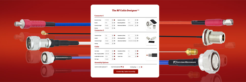
- Commercial Electronics
- Energy
- Industrial Automation
- Medical
- Military/Defense
- Telecommunications
- Test & Measurement
- Transportation
How we helped Mayo Clinic hospital with their RF Components
