
What Is RF Interconnect?
RF Interconnect is another term for RF connections between devices, boards, ports, RF cable assemblies, waveguide, probes, antenna, and etc. As discussed in a previous blog post, What is an RF Connection, RF interconnects are a method of transferring RF signals from one node to another either conductively, through a transmission line (RF coaxial connectors/ coaxial cable assemblies), or through a waveguide. It can be argued that an RF antenna is also a form of interconnect, though it is really a transducer that converts electrical signals carried conductively to a free-space wavefront.
Key Takeaways
RF interconnects are the backbone of any RF or microwave system because they carry signals from module to module, antenna to transmitter, or measurement equipment to DUT. The right interconnect choice preserves signal integrity by ensuring proper impedance matching, low loss, and stable shielding. Cable type, whether flexible coax, semi-rigid, corrugated, or waveguide, must be selected based on frequency, power level, run length, and environmental conditions. Connectors and adapters must be high-quality and correctly implemented to maintain performance. Good interconnect design is not optional; it directly impacts link reliability, signal quality, and system longevity.
What Is RF Interconnect
RF interconnect refers to the set of cables, connectors, adapters, and waveguides that join radio frequency components in a communication or test system. Whenever you need to transmit RF or microwave energy from one module to another, for example, from an amplifier to an antenna, or from a signal generator to a receiver RF interconnect ensures that the signal is delivered with minimal loss, proper impedance matching, and adequate shielding. Good interconnect design preserves signal integrity, reduces reflections, and supports overall system performance.
Interconnects include coaxial cables, semi-rigid cables, corrugated or waveguide lines for higher frequency or high power links, as well as connectors, adapters, and assemblies that join these elements. Choosing the right interconnect components is crucial for matching impedance (often 50 Ω), minimizing insertion loss, and maintaining shielding against interference.
Why RF Interconnect Matters in RF Design
In RF systems, even small mismatches or poor-quality cabling impact performance dramatically. RF interconnects handle key tasks: they carry signals with minimal attenuation, maintain stable impedance so reflections are minimized, shield against electromagnetic interference (EMI), and provide mechanical flexibility or rigidity depending on the application.
For example, in a test bench or lab environment, flexible coax cable may be suitable for frequent reconnection. In a high-frequency or high-power system, a semi-rigid or waveguide interconnect can provide low loss and stable performance under stress. Poor interconnects lead to signal degradation, noise, connector failures, or unstable measurements. Thus, designing with correct interconnects protects both signal quality and hardware longevity.
Key Specifications to Check When Choosing a Limiter
When selecting an RF limiter for a receiver or front-end design, several key specifications determine how well the device will protect sensitive components. The most important parameter is input power handling, which defines the maximum RF power the limiter can safely withstand without damage. Flat leakage and residual output power indicate how much energy reaches the protected circuitry during high-power events, with lower values providing better protection. Recovery time is another critical factor—this measures how quickly the limiter returns to normal operation after a high-power pulse, directly impacting system sensitivity in pulsed radar or communications systems. Designers should also evaluate insertion loss, since excessive loss can degrade signal-to-noise ratio in low-power paths.
When speaking of RF interconnect, this generally refers to connections between circuit boards, devices, subsystems, systems, and between interconnects. The reason RF interconnects are used, especially transmission lines and waveguides, is because containing the RF signal energy in a transmission line or waveguide is generally a much more efficient method of transferring that signal energy from one point to another, that signal is shielded to some degree from interference/noise injections from outside sources, and these types of connections help to ensure that the signal is harder to intercept, jam, block, or otherwise interfere with.
There are a variety of types of transmission lines and waveguides, as well as other types of RF interconnects. The most common types of RF transmission lines that most engineers and professionals are aware of are coaxial transmission lines. These make up the bulk of RF interconnects between modules, subsystems, and systems. Waveguides such as rectangular, circulatory, and elliptical waveguides are also commonly used for high power, precision, and extremely high frequency signals in the millimeter-wave range. There are other types of transmission lines, including planar transmission lines used on planar substrates/laminates, such as PCB, low-temperature co-fired ceramic (LTCC), high-temperature co-fired ceramic (HTCC), flex-PCBs, semiconductors, and others. Example planar transmission lines are coplanar transmission lines and striplines, of which there are a variety of configurations. There are also planar waveguides, such as a microstrip.
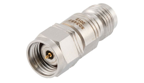
There are also a variety of different connector and adapter styles that should be included in the RF interconnect categories. These include adapters from different transmission line types, such as a planar transmission line to a coaxial transmission line, or between different types of coaxial connector types. There are also adapters between coaxial transmission lines and waveguides. It is important to note here that coaxial transmission lines are broadband RF signal carrying medium, while waveguides are banded based on the geometry and structure. Hence, any adapter between a coaxial transmission line and a waveguide will have a lower cutoff frequency limited by the waveguide and a higher cutoff frequency either limited by the coaxial transmission line or waveguide, whichever is lower.
It can be argued that certain resonant coupling structures can also be considered interconnects, as well as components such as directional couplers and probes. However, passive structures like directional couplers and probes are generally not considered RF interconnects as they lack a conductive path for the signals and rely on coupling to fields external to the conductors of the main RF signal paths.
Recommendations for Engineers and Designers
Begin every RF project by planning the interconnect path. Determine required frequency range, power level, and cable run length. Choose cable types that minimize loss under those conditions. Use quality connectors and ensure impedance continuity. For high-power or high-frequency applications, consider semi-rigid cables or waveguides. Always keep cable runs as short as practical. Avoid unnecessary bends or mechanical stress. In test or prototyping environments, prefer flexible cable assemblies for ease of use. If the setup will be permanent or require stable performance, use rigid or semi-rigid interconnects. For outdoor or harsh environments, choose cables and connectors rated for weather, vibration, and environmental exposure. Use well-designed cable assemblies rather than ad-hoc wiring to maintain signal integrity and reliability.