


Primer on Coaxial Connectorized Directional Couplers
Key Takeaways
- Coaxial connectorized directional couplers are passive RF components designed to sample a small portion of signal power without disrupting the main transmission path.
- They use standard coaxial connectors such as SMA, N-Type, 2.92 mm, or 1.0 mm, making them easy to integrate into existing RF systems and test setups.
- These couplers enable accurate forward and reflected power measurements, supporting VSWR, return loss, and transmitter health monitoring.
- They are widely used in RF test benches, telecom infrastructure, radar systems, and aerospace applications.
- Compared to waveguide couplers, coaxial directional couplers offer greater flexibility, compact size, and broadband performance, especially at lower to mid-microwave frequencies.
What Is a Coaxial Connectorized Directional Coupler?
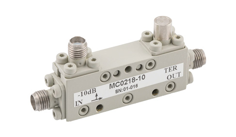
A coaxial connectorized directional coupler is a passive RF/microwave component designed to sample a small, controlled portion of signal energy traveling through a coaxial transmission line while maintaining the integrity of the main signal path. These couplers use external coaxial connectors (such as SMA, N-type, or 1.0 mm) to interface with test equipment and RF systems, combining broadband performance with convenient connectivity
How Coaxial Connectorized Directional Couplers Work
The operation of coaxial directional couplers is based on electromagnetic coupling between transmission lines. When RF energy propagates along the main cable path, a portion of the electromagnetic field interacts with a coupled secondary path. Depending on the physical design, such as coupled lines, slots, or planar circuit structures within the coupler, a portion of the forward (and in some designs, reverse) signal is siphoned off to a secondary port. Careful mechanical design and impedance matching ensure that this coupled signal accurately represents the forward or reflected energy with minimal disruption, high directivity, and low insertion loss.
In RF test and measurement, communication, and RF sensing, it is often necessary to extract a portion of the incoming and/or outgoing signal energy for measurement, monitoring, or signal processing purposes. In these cases, one of the fundamental passive components used to do this are RF Directional Couplers. Directional couplers differ from other RF couplers in that they are designed in a way to allow for extraction of a small portion of the signal energy from the forward and/or reverse directions by a set coupled amount with appropriate phase. As it isn’t always necessary to extract signal energy from both directions, in practice, some direction couplers have either the forward or reverse port terminated with a matched load to the other port impedances. This termination can be done during production or made available to the user via access to all of the ports. A directional coupler with both forward and reverse coupled ports accessible is typically referred to as a bi-directional coupler.
Whether it is a pre-terminated directional coupler or not, many directional couplers are fabricated with external coaxial connector ports. Directional couplers can commonly be found that are made with surface mount technology (SMT), coaxial connectors, waveguide ports, or directly fabricated using planar circuit technologies (i.e. PCB). Coaxial connectorized directional couplers could be made in a variety of ways, including as simply as modifying a larger and smaller coaxial cable with coupled center conductors and united shielding. It is more often that coaxial directional couplers are made using planar circuit technologies and then installed in a coaxial package with end-launch coaxial connectors attached to the circuit board. However, there are still directional couplers made from precision machined cavities. For higher frequency directional couplers, a coaxial directional coupler may even be made using a surface mount directional coupler broken out to RF ports attached to coaxial connectors. An example of a component that may be fabricated in one of these ways is a 1.0mm Coaxial Directional Coupler To 110 GHz.
Coaxial directional couplers benefit from coaxial connector broadband performance, which operates from DC to the highest frequency of the internal coupler structure or the coaxial connector standards, whichever is lower. Some coaxial connectorized directional couplers may be optimized for frequency operation at certain ranges, which may mean they are only specified across those ranges, and not the full coaxial connector standard operating frequency range. With coaxial connectorized directional couplers, the impedance of the ports is critical, as these need to be carefully matched to ensure balance across the coupler ports and proper coupling. Coaxial directional couplers are available that cover ranges from tens of megahertz at high power levels to over 100 GHz at proportionally lower power levels.
FAQs (Frequently Asked Questions)
Q1: What is a coaxial connectorized directional coupler?
A: A coaxial connectorized directional coupler is a device that samples RF power traveling through a coaxial transmission line using standard RF connectors, allowing measurement of signal strength, forward power, or reflected power.
Q2: How does a coaxial directional coupler work?
A: It works by electromagnetically coupling a small portion of the RF signal from the main transmission path into a secondary port. The design ensures that only signals traveling in a specific direction are sampled, providing accurate measurements.
Q3: What is the difference between a coaxial and a waveguide directional coupler?
A: Coaxial directional couplers use coaxial connectors and are typically more compact and broadband, while waveguide couplers are better suited for very high-frequency and high-power applications.
Q4: What are common applications for coaxial directional couplers?
A: They are commonly used for RF testing, VSWR and return loss measurements, transmitter monitoring, telecommunications infrastructure, and defense or radar systems.
