Types Variable/Programmable Attenuators For Receiver Sensitivity Testing
by Peter McNeil | Feb 07, 2023
Receiver sensitivity testing is one of the most crucial tests for a prototype or production receiver. This type of test is often performed to either determine the extent of the capability of a new receiver design/communication technology, or as part of a certification test for a receiver designed to meet the requirements of a wireless standard. Without receiver sensitivity testing it would be extremely difficult to determine if a given receiver met the performance requirements of a given standard, or to properly plan out wireless network distribution.
A key element that can be used with receiver sensitivity testing is an RF Attenuator. RF Attenuators are used in receiver sensitivity testing to ensure that the power delivered to the receiver-under-test (RUT) is set at the desired low power specified for the test, or as low as is needed to test the extent of the sensitivity of a receiver. Receiver sensitivity testing can be performed with Fixed Attenuators while using a frequency or signal source with variable power output. However, it is more common to use a frequency generator/signal generator within the device’s most linear and low noise floor (NF) power range, which may be somewhat limited. This is why it is more common to use Variable Attenuators for receiver sensitivity testing.
There are a variety of Variable Attenuators that may be used for this application: Analog/Continuously Variable Attenuators, Step Attenuators, Voltage Variable Attenuators, and Programmable Attenuators. If there is very little complexity to the power range for testing and manual adjustment or adjustment based on analog feedback is necessary, Continuously Variable, Voltage Variable, or Step Attenuators may be applicable. In most test applications it may be desirable to instead use a quality Programmable Attenuator with adequate range and specifications that can meet the majority of the requirements for a test laboratory or automated test installation.
Using a Programmable Attenuator always for the calibration plane of the receiver sensitivity test to be brought to the input of the RUT, while still having a flexible range of input signal power. This enhances the accuracy of receiver sensitivity testing and can improve the dynamic range of the test as well.
Depending on the available or preferred control technologies, any of the common types of Programmable Attenuators are suitable for this type of testing: CMOS Controlled Programmable Attenuators, Relay Controlled Programmable Attenuators, TTL Controlled Programmable Attenuators, USB Controlled Programmable Attenuators.
Related articles
Peter McNeil | Feb 21, 2024 | Attenuator
RF Coaxial Attenuators, such as Coaxial Fixed Attenuators and Coaxial Variable Attenuators, are used in a wide variety of RF applications to control signal levels, improve impedance matching, and enhance the accuracy of signal generator outputs in test setups. The main use of these components is in coaxial devices, systems, and setups that require signal level control that is either fixed or adjustable.
Fixed coaxial attenuators are more commonly used for impedance matching improvement in environments where the VSWR at a node is high enough to develop unwanted standing waves. This type of attenuator set at a relatively low level provides enough attenuation to prevent the standing wave from building up to that unwanted threshold. As the standing wave bounces between the mismatched nodes through the interconnect, an attenuation placed in between steadily depletes the energy of the standing wave.
In other cases fixed attenuators are used for signal level control where the signal level is generally known and needs to be reduced by a predetermined amount. In high precision scenarios this involves taking into account the total insertion loss and attenuation of all of the interconnects involved in the signal chain between the nodes where having an accurate degree of signal loss is needed. In this case it is often useful to have a fixed coaxial attenuator that is also an adapter if the coaxial connectors on either end of the attenuator are different from each other. This eliminates the need to have a separate adapter or coaxial cable assembly with different connector heads, and may allow for less uncertainty in the interconnect scheme.
Variable attenuators present a more diverse range of use cases than fixed coaxial attenuators. Variable attenuators are used for signal level control, which can include calibrating a test setup where a signal generator is needed, such as receiver sensitivity testing. There are a variety of different types of coaxial variable attenuators, including programmable attenuators, step attenuators, continuously variable attenuators, and voltage variable attenuators. Step attenuators are typically manually adjusted attenuators with fixed attenuation increments that can be adjusted from a low setting to a maximum attenuation setting that engages all of the internal attenuators within the device. Continuously variable attenuators allow for a manual control knob to adjust the attenuation level to a precise amount that isn’t based on discrete steps, which may be useful for tuning a test setup to achieve a very precise signal level output. Voltage variable attenuators are like continuously variable attenuators with the exception that the attenuation level is controlled via a voltage input. Lastly, a programmable attenuator is a variable attenuator with programmable attenuation levels generally set by the a digital communications interface.
Peter McNeil | Feb 07, 2024 | RF Attenuator
Key Takeaways
- A fixed RF attenuator is a passive device that reduces signal amplitude by a set amount (in dB), useful wherever the incoming signal is stronger than what downstream equipment can handle.
- Besides lowering signal power, attenuators help improve impedance matching and reduce standing waves caused by impedance mismatches, which can otherwise degrade signal integrity.
- Fixed attenuators come in various interconnect types: coaxial, waveguide, surface-mount (planar), or even bare-die designs making them versatile across many RF system architectures.
- Key specs when selecting an attenuator include frequency range, attenuation value, insertion loss, VSWR, impedance, power handling (CW/peak), connector type, and thermal/temperature ratings.
- High-power applications may require attenuators with thermal management from simple metal housings to heatsinks or active cooling to safely dissipate absorbed signal energy.
What Is a Fixed RF Attenuator & Its Core Purpose
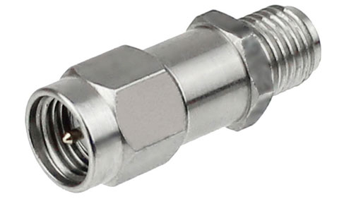
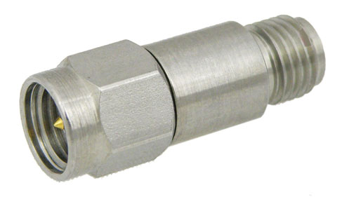
A fixed RF attenuator is a passive component designed to reduce the power level of an RF signal by a specific, pre-set amount. Instead of amplifying or shaping the signal, it simply weakens it in a controlled and predictable way, typically expressed in decibels (dB). This makes attenuators essential anytime the input signal is too strong for a downstream device, such as a receiver, mixer, LNA, or test instrument. Beyond reducing signal amplitude, fixed attenuators also help improve impedance matching between components.
When equipment with slightly mismatched impedances is connected, reflections and standing waves can occur, causing distortion and measurement of inaccuracies. By inserting an attenuator, those reflections are dampened, leading to cleaner signal transmission and more stable system behavior. In short, the core purpose of a fixed RF attenuator is to protect sensitive components, optimize system performance, and maintain consistent signal flow.
Key Specifications to Consider Before Choosing an Attenuator
Selecting the right fixed RF attenuator requires close attention to a few essential technical parameters. The first is the attenuation value, which dictates how much the signal will be reduced. Common values include 3 dB, 6 dB, 10 dB, and 20 dB. Next is the frequency range, which must fully cover your system’s operating band to avoid performance roll-off. Power handling is another critical factor: attenuators must safely dissipate the RF energy they absorb, especially in high-power or continuous-wave systems.
Equally important is VSWR, a measure of how effectively the attenuator maintains impedance matching; lower VSWR values lead to fewer reflections and more accurate system performance. Connector type also matters, as the attenuator must physically and electrically integrate with your coaxial or waveguide infrastructure. Lastly, in demanding environments, consider thermal stability, temperature ratings, and mechanical durability, which can significantly affect long-term reliability.
Typical Use Cases — When and Why You Use Fixed Attenuators
Fixed RF attenuators are used in a wide variety of RF and microwave systems because they solve multiple signal-level and impedance challenges. In test and measurement environments, attenuators help prevent sensitive instruments—like spectrum analyzers, SDRs, and network analyzers from being overloaded by strong signals. They are also essential for calibrating systems, simulating weak-signal conditions, and creating controlled test environments. In communication systems, attenuators help optimize transmitter-to-receiver links, maintain proper gain distribution, and balance multi-carrier or multi-antenna setups. They’re also used in radar, satellite, and 5G applications to manage power levels during development and field testing.
RF circuits useful for lowering signal amplitude by absorbing a fixed amount of RF energy are called fixed RF attenuators. These devices are also used for dissipating excess signal energy, enhancing impedance matching between two components/devices by lowering the standing waves created by impedance mismatch, and as part of more complex electronic protection for sensitive components. The main use of fixed RF attenuators is for signal level conditioning, typically when the range of input signal energy is known and is greater than that of the desired signal energy at the port attached to the attenuator.
An RF fixed attenuator is specified as a signal attenuation value over a range of frequencies. These attenuators are simple resistive circuits designed to present a nominal impedance at the input and output and may be balanced or unbalanced depending on if the attenuator is meant for balanced transmission lines or balanced transmission lines. Attenuators are made for a variety of different interconnect types, such as coaxial, twisted pair, waveguide, surface mount technology (SMT) as part of planar transmission lines/waveguide (microstrip, stripline, coplanar waveguides, etc.), or as bare die. RF fixed attenuators for waveguide are fabricated differently than coaxial or SMT attenuators with discrete resistive components, often as a waveguide packed with RF absorbing materials.
Key Fixed RF Attenuator Performance Specifications
- Frequency range [Hz]
- VSWR [ratio]
- Insertion loss [dB] *lowest attenuation value
- Attenuation value(s) [dB] *sometimes given over frequency
- Impedance [Ohms]
- Velocity of propagation [%c]
- Power handling (CW, peak) [Watts]
- Attenuation accuracy [+/-dB]
- Interconnect (Connector type 1 and 2 for coaxial, waveguide flange type for waveguide, SMT, etc.)
- Temperature range of operation [deg C]
- Thermal management (heat sink capability, active/passive)
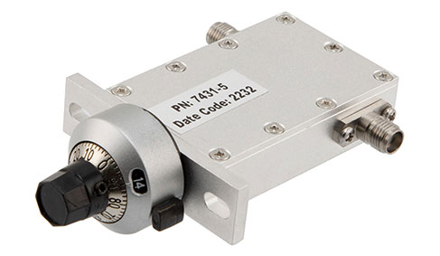
RF attenuators are typically selected based on their attenuation level, frequency range, and power handling capability. In some applications the accuracy of the attenuation is very important, such as test/measurement, metrology, and precision sensing. In other applications, the power handling is most critical. RF fixed attenuators made for high RF power handling applications often include passive or active thermal management. This can be as simple as a metallic housing, a heatsink, a heatsink with active air cooling, or even as a liquid cooled system.
Fixed RF attenuators are foundational elements used throughout the RF industry for test and measurement, sensing, communications, and in virtually every environment RF technology is used. There are RF fixed attenuators available that meet the wide variety of automotive, aerospace, space, naval/maritime, applications.
Frequently Asked Questions (FAQs)
Q1: What does a fixed RF attenuator do?
A: A fixed RF attenuator reduces the amplitude of an RF signal by a fixed amount (e.g., 3 dB, 6 dB, 10 dB), ensuring that downstream components receive a safe and manageable signal level. This helps prevent overload and distortion.
Q2: Why not just use a cable or amplifier with lower power instead of an attenuator?
A: Because an attenuator does not just reduce power, it maintains proper impedance matching and minimizes reflections, which cables or mismatched amplifiers alone may not do reliably. This improves signal integrity and stability in the chain.
Q3: In what situations are fixed attenuators typically used?
A: They are widely used in test & measurement setups, communications systems, receiver protection, antenna testing, and anywhere signal levels need to be controlled, or impedance mismatches mitigated.
Peter McNeil | Feb 14, 2024 | RF Terminations
At 26 GHz, there is substantial atmospheric absorption and much higher free space loss than at sub-6 GHz frequencies. Moreover, the interconnect such as 26 GHz attenuators and 26 GHz terminations, to drive a 26 GHz system intrinsically must be more compact than lower frequency interconnect, meaning that the power handling and loss of interconnect suitable for 26 GHz is greater than that of lower frequency interconnect.
Key Takeaways
- 26 GHz attenuators and terminations are essential for emerging high-frequency systems, including 5G FR2, radar, and satellite communications.
- High-precision attenuators help control signal levels, protect receivers, and maintain system linearity at mmWave frequencies.
- 26 GHz terminations ensure proper impedance of matching, reduce reflections, and improve accuracy in test setups.
- These components must be engineered with low VSWR, stable attenuation, and high-power handling to perform reliably at 26 GHz and beyond.
- Choosing the right part depends on factors such as connector type, attenuation accuracy, operating bandwidth, power rating, and environmental robustness.
Why 26 GHz Components Matter for Modern RF Systems
As RF systems push deeper into the millimeter-wave range, the need for components that can maintain performance at higher frequencies has become essential. The 26 GHz band is particularly significant because it sits at the lower end of mmWave, offering a balance of bandwidth, reliability, and manageable propagation loss. Technologies like 5G FR2, advanced radar, point-to-point microwave links, and satellite terminals increasingly rely on this frequency range for high-data-rate, low-latency communication. For these systems to operate efficiently, every element—from connectors and cables to attenuators and terminations—must maintain low VSWR, stable signal characteristics, and consistent power handling at 26 GHz. This is why dedicated 26 GHz components matter: they ensure signal integrity, minimize reflections, and deliver predictable performance in demanding high-frequency environments.
Key Applications for 26 GHz Attenuators
26 GHz attenuators play a critical role in controlling signal levels, protecting sensitive components, and improving accuracy in both field and lab settings. In 5G FR2 test environments, they are used to adjust signal strength when evaluating radio units, antennas, and user equipment operating near 26–28 GHz. In radar systems, attenuators help balance high-power transmit signals to ensure proper receiver sensitivity and prevent front-end overload. They’re also widely used in satellite communication links, particularly for Ka-band terminals to fine-tune uplink and downlink signal paths. RF labs rely on 26 GHz attenuators during calibration, verification, and production testing to simulate real-world conditions and evaluate device performance under controlled power levels. Across all of these applications, the goal is the same: stable, accurate attenuation that holds its value across the full 26 GHz bandwidth.
Choosing the Right 26 GHz Attenuator or Termination
Selecting the right attenuator or termination for 26 GHz operation requires balancing electrical and environmental requirements. Key specifications include connector type SMA and 2.92 mm are the most common at this frequency, and the operating bandwidth, which should cover at least DC–26.5 GHz to ensure full compatibility. Attenuation accuracy is crucial, especially in precision test setups where even small variations can lead to measurement errors. Power handling also matters fixed attenuators must withstand both continuous-wave and peak loads without drifting or degrading.
For terminations, low VSWR and good thermal management ensure that excess RF energy is safely absorbed without reflection. Environmental factors such as vibration, temperature stability, and housing durability are equally important for outdoor or defense applications. Ultimately, the right choice depends on how consistently the component can maintain performance at 26 GHz under the specific demands of your RF system.
26 GHz is a very active chunk of spectrum firmly in the millimeter-wave frequencies. As with many portions of the spectrum and RF components/devices/systems, 26 GHz doesn’t merely refer to the singular frequency of 26 GHz, but the spectrum around that frequency. For instance, there are automotive radar applications at 24 GHz to 24.25 GHz (an ISM band), which some 26 GHz hardware may be suitable for. There are also many other applications, such as Ultra-Wide Band (UWB) that operates from 21 GHz to 26 GHz, that could be considered part of the 26 GHz spectrum, Moreover, 24.25 GHz to 27.5 GHz marks the 5G n258 band (3GPP band n258). Hence, there are a variety of applications operating around 26 GHz where Attenuators and Terminations suitable for 26 GHz could be used.
This means that each individual transmission path at 26 GHz can carry much less signal energy and dissipates more signal energy than lower frequency transmission paths. This is why at 26 GHz, many applications use array antennas, otherwise known as advanced/active antenna systems (AAS). This means that many 26 GHz applications have many transmission paths to provide power and conditioned signals to array antennas, including phased array antennas. Depending on the architecture of the advanced/active array, there may be many transmission paths that require attenuation during testing or use, or terminations during testing/prototyping. This is where 26 GHz attenuators and 26 GHz terminations come into play. These components are vital for use during operation for AAS, but also during the development and testing phases. Attenuators are used to condition the power level of a signal during testing or use and increase the precision of a test by conditioning the output signal energy of a test signal source. Terminations are instrumental in providing impedance match loads at the end of a transmission path to prevent reflections. This is useful during calibration but also when a path may not be used and that signal energy needs to be shunted instead of reflected back to the source.
FAQs (Frequently Asked Questions)
1. Why are 26 GHz attenuators important in RF systems?
A: They regulate signal levels to prevent overload, maintain system linearity, and ensure consistent performance in high-frequency applications like 5G and radar.
2. What do 26 GHz terminations do?
A: Terminations absorb unused RF energy, ensuring proper impedance of matching and reducing reflections that can distort measurements.
3. Can 26 GHz components be used below 26 GHz?
A: Yes, most broadband and maintain stable performance across lower frequencies as well.
4. Where are 26 GHz attenuators commonly used?
A: In 5G FR2 testbeds, mmWave radios, phased-array radar, satellite uplink/downlink systems, and RF labs.

