Peter McNeil | Mar 27, 2024 |
RF Attenuator Fixed Attenuator RF Attenuator
Key Takeaways
- RF fixed attenuators using 3.5 mm connectors provide precise signal attenuation for RF and microwave systems up to 26.5 GHz, with some designs functional beyond the 30+ GHz range.
- These attenuators help reduce incoming signal levels to protect sensitive receivers, mixers, and test equipment from overload.
- Fixed coaxial attenuators can also improve impedance matching and minimize standing waves by lowering reflected power between mismatched ports.
- The inline design with 3.5 mm connectors makes installation compact and convenient, suitable for prototype, production, and system integration environments.
- Typical designs support 1-2 W power handling, which is adequate for many mmWave communications, phased arrays, and sensing applications.
What is RF Fixed Attenuators?
RF fixed attenuators are passive microwave components designed to reduce the amplitude of an RF signal by a defined amount while maintaining the characteristic impedance of the transmission line, typically 50 Ω. Unlike variable attenuators that allow selectable attenuation, fixed attenuators provide a precise, stable attenuation value (such as 3 dB, 6 dB, or 10 dB) that remains constant across their specified frequency range. These devices play a crucial role in RF and microwave systems by protecting sensitive components from high power levels, balancing signal levels between circuits, and improving measurement accuracy in test environments. Because they introduce a controlled loss, fixed attenuators can also help reduce reflections and stabilize system performance when used appropriately within signal chains.
Why 3.5 mm Connectors Matter in High-Frequency Attenuators
3.5 mm connectors are precision coaxial interfaces engineered for microwave and millimeter-wave performance, making them an ideal choice for fixed attenuators that must operate effectively at higher frequencies, such as up to 26.5 GHz and beyond. Compared to larger connector types, the 3.5 mm interface provides consistent impedance control and minimal signal distortion over wide frequency bands. This connector type features a threaded coupling mechanism that ensures a secure, low-VSWR connection that is essential in high-frequency applications where even slight mismatches can degrade signal integrity. The mechanical precision of 3.5 mm connectors helps attenuators maintain reliable performance under the demanding conditions of RF circuitry, test setups, and compact system integration, where both electrical performance and physical stability are required.
How RF Fixed Attenuators Improve Signal Conditioning
RF fixed attenuators improve signal conditioning by reducing excessive signal levels to a range suitable for downstream circuitry while preserving overall signal quality. In practical terms, they protect sensitive receivers, amplifiers, and measurement instruments from overload and compression, which can distort signal interpretation or damage components. Attenuators also help balance signal paths in multi-stage networks, ensuring that each stage sees an appropriate power level for optimal performance. In test and measurement environments, fixed attenuators are frequently used to calibrate signal levels, reduce reflection effects, and improve measurement repeatability by stabilizing the source of impedance seen by test instruments. By integrating fixed attenuators with 3.5 mm connectors into RF systems, engineers can achieve better control over signal amplitude, reduce noise contributions from mismatches, and maintain system integrity across high-frequency applications up to 26.5 GHz and beyond.
Fixed attenuators are useful for a variety of signal conditioning needs in RF systems. Fixed RF attenuators can be used to provide high precision and known attenuation of incoming signals that may exceed the input requirements of devices like sensitive receivers or mixers or can be used to minimize the standing waves developed between mismatched impedances.
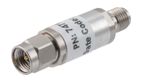
In test and measurement applications or millimeter-wave (mm-Wave) communication and sensing, fixed attenuators are key elements used during prototype testing/development, quality/verification, troubleshooting, or even integrated in systems. RF Fixed Attenuators with 3.5mm Connectors are ideal mm-Wave coaxial attenuators as the 3.5 mm connector is specified to 26.5 GHz but can be used functionally as high as 33 GHz or 34 GHz.
3.5mm connectors are mating compatible with SMA connectors, though SMA connectors typically have a much lower frequency limit, even with precision design units. The specified frequency range of 3.5mm connectors covers the HF, VHF, UHF< L, S, C, X, Ku, and nearly all of the K-band. However, 3.5mm connectors will also operate to much of the Ka band. If operating a 3.5mm RF fixed attenuator out of the specified range, the attenuation level, VSWR, power handling, and other performance criteria may be degraded somewhat in the higher frequency regime.
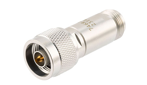
A benefit of fixed, coaxial attenuators is that they can be made to be installed inline with the coaxial interconnect. An inline design mitigates the need to design a specific place to secure a mountable attenuator and can even be installed on bulkhead ports internally or externally to housing or shielding. Since inline fixed attenuators tend to be compact, often not much larger than the coaxial connector itself, these units tend to have lower power handling than coaxial attenuators with integrated heatsinks or other thermal management features. Often 1 to 2 Watts of power handling is adequate for a mm-Wave inline attenuator operating in the K-band, as modern communications and sensing applications at these frequencies now tend to rely on advanced/active antenna array (AAS) technology, such as phased arrays and switched arrays that have the signal power divided amongst several signal paths. With low enough fixed attenuators it is also possible to use these inline attenuators to equalize the attenuation between several signal paths of varying lengths, though phase correction will still need to be provided with additional hardware.
Recommendations
- Select the right attenuation level: Choose fixed attenuators with attenuation values that suit your system’s power levels and dynamic range to avoid over- or under-attenuation.
- Match impedance: Ensure the attenuator’s 50 Ω impedance aligns with your system to prevent additional VSWR or signal reflection issues.
- Use inline mounting: Inline 3.5 mm attenuators simplify installation in tight systems and reduce the need for additional mounting hardware.
- Consider power handling: Verify that the attenuator’s power rating (typically 1–2 W) meets your application needs, especially for high-power RF or mmWave links.
- Plan for frequency range: If your system operates near or above 26.5 GHz, ensure the attenuator is specified for that range and understand that performance may change at extended frequencies.