


A RF switch is a basic building block of many RF circuits used in communication, sensing, and test & measurement applications. RF switches are used whenever a signal path needs to be optionally opened/closed, or when specific signal paths need to be selected. An example of this is in a radar RF Front End (RFEE) when the path to the antenna needs to be switched between the transmitter during transmission and the receiver during reception and it is undesirable to have the transmission signal energy directed to the receiver. In this example, the RF switch also provides some isolation between the transmitter and receiver in the radar.
RF Switch
Related articles
Peter McNeil | Oct 26, 2021 | RF Switches
RF switches are prevalent in many RF systems for a variety of uses. Switches are commonly used to switch between a receive or transmit channel at the port of an antenna, switch between filter channels, or used in matrices to switch test channels for high throughput automated testing or to extend the port count of a vector network analyzer.
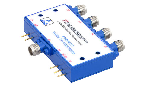
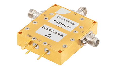
We offer several popular types of RF switches including Electromechanical Relay Switches that have a minimum frequency of DC and a maximum frequency range between 4 GHz and 18 GHz, PIN Diode Switches that feature a single pole single throw (SPST) design with a maximum insertion loss between 1.2 dB and 3.5 dB, and Manual Switches that employ a make before break configuration with manual toggle actuators.
RF switches may be integrated in RF semiconductor devices as solid-state switches, discrete solid-state, or micro electrical mechanical machine (MEMS) switches may be relatively large connectorized components that rely on embedded motors to engage the switch mechanisms for different paths. RF switches may have one to many paths they may switch between and may also switch from multiple inputs to a series of outputs simultaneously. Configuring several switches to allow for any input path to switch to any of the output paths of the switch enables the creation of a multiplexer or demultiplexer. If only one input can be switched to a given output at a time, this is known as a blocking matrix switch.
Hence, the complexity of RF switches may be very high, and may have a large number of input and output ports. For example, there are commercially available switch matrices with over 128 ports, which are used in antenna array testing. Testing simple RF switches can be as simple as connecting the switch to a VNA and gathering the transmission and reflection parameters from both ports at either of the switch states. With more complex switches, each port needs to be tested in each of the switch states. There are also some applications where understanding the dynamics of the switch during an on-to-off and off-to-on switching action are also important to prevent various peak load situations that may cause undesirable peak power levels seen at the device or along the signal path.
Therefore, beyond multiport VNA testing of a switch, which may be done with a VNA with a switch matrix accessory, signal generators and spectrum analyzers/power meters may also be used to test dynamic switch performance in some cases. The critical performance parameters commonly specified for RF switches are as follows:
- Impedance (on and off state)
- Bandwidth
- Insertion Loss
- Return loss (also over temperature, known as IL temperature coefficient)
- VSWR
- Isolation
- Crosstalk
- Switching speed or switching time (rise time and fall time)
- Power handling or RF input power (continuous wave or peak)
- DC Power dissipation
- Positive operating voltage and biasing (solid state switches)
- Hot switching capability
- Switch actuation power/voltage/current or signal (may be analog or digital)
- Reflective or termination
- Input third order intercept (solid state)
- Third order intermodulation (electromechanical)
- 1 dB compression point or 0.1 dB compression point
- Minimum operating life in number of cycles
- Temperature range of operation
As some RF switches are used in mission critical applications, rigorously testing the switch’s reliability and performance in extreme environments is also essential. In these cases, accelerated stress testing is often performed to determine a minimum operational lifespan based on a number of switching cycles. Also, some RF switches may need to be switched while signal power is applied, known as hot switching, which may result in different power handling capability than the switch in a static on or off position. For switches with multiple RF paths, isolation testing using a multiport VNA is crucial as some switch technologies may allow for some signal power to leak from one path to another.
Learn more about Fairview Microwave’s RF Switches.
Peter McNeil | Apr 24, 2024 | RF Switches
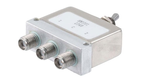
RF Switches are integral to many RF systems with different signal paths and functions, as well as RF test & measurement. RF Manual Switches differ from automated switches and switches with electrical actuation in that they require manual switch adjustment. In the modern times of artificial intelligence/machine learning (AI/ML) and extensive multiport RF systems with Advanced/Active Antenna Arrays (AAS), you may ask, is there still a place for manual RF switches? The answer is that regardless of how complex modern RF systems are there is still often a need during prototyping and testing for a human operator to switch between different channels. It is also possible that a production system will have different modes that require a human operator to set up and including a manual switch is a cost savings with potential performance and footprint benefits that even electromagnetic switches don’t offer.
Key Takeaways
- Manual RF switches remain important because they provide a simple, low-profile, and power-free way to switch RF signal paths — especially useful during lab testing, prototyping, or occasional multi-band configuration.
- Compared to automated or solid-state switches, manual switches require no control of voltage or bias lines, which reduces system complexity and potential points of failure.
- Well-designed manual RF switches can deliver comparable RF performance to electromechanical switches: low insertion loss, good isolation, moderate-to-high power handling — sometimes better than solid-state alternatives.
- They are especially useful in applications where switching frequency is low (i.e., few changes per day) — such as antenna band switching, redundancy setup, test instrumentation routing, or occasional signal path changes.
- However, manual switches are not suitable for applications requiring frequent switching, rapid auto-selection, or precise timing, because manual actuation is too slow and cannot be automated easily.
What Is a Manual RF Switch — Basic Concept & Operation
A manual RF switch is a mechanical switching device that allows an operator to physically select and route RF signals between different signal paths. Unlike automated, PIN-diode, or relay-based RF switches, manual switches require human interaction—typically through a front-panel knob, lever, or toggle. Internally, these switches use mechanical contacts, rotary selectors, or coaxial switch mechanisms to establish or break RF connections while maintaining controlled impedance across the signal path.
The goal is to provide a reliable, low-loss method of routing signals in scenarios where automatic or remote switching is unnecessary. Their simplicity also contributes to excellent RF performance, long life, and minimal signal distortion across wide frequency ranges.
Why Manual RF Switches Still Matter in Modern RF Systems
Even in an era dominated by digital control, remote switching, and automated RF test systems, manual RF switches remain highly relevant because they offer unmatched simplicity, reliability, and cost efficiency. For applications requiring occasional routing changes not continuous or high-speed switching manual switches eliminate the complexity of control circuits and firmware. They also provide superior robustness since mechanical switching avoids issues like switching noise, transient spikes, or power-supply errors. In mission-critical environments such as aerospace ground stations or field testing, manual switches provide a dependable fallback solution that continues operating even when automated systems fail. Their straightforward operation and stable RF characteristics make them indispensable in test benches, prototyping setups, and redundant RF signal paths.
Key Performance Considerations: Insertion Loss, Isolation, Power Handling & Frequency Range
When selecting a manual RF switch, engineers must consider several performance factors. Insertion loss determines how much signal strength is lost when the switch is engaged; lower values help maintain system sensitivity, especially in receiving chains. Isolation measures how well unwanted signal paths are suppressed, preventing leakage or crosstalk when switching between channels, a critical factor for test environments and multi-antenna systems. Power handling defines the maximum RF power the switch can safely manage without breakdown or excessive heating, making this parameter essential for high-power transmit systems.
Frequency range is also crucial; broadband switches must maintain stable performance across varying bands, from MHz to tens of GHz, without degrading VSWR. Mechanical durability, switching life, and connector type further influence long-term reliability and system integration.
Manual RF switches only require an operator to have access to a relatively small and low-profile switch actuator. Electromagnetic switches and solid-state switches require some type of power input line and a signal line in addition to the RF ports. This means that there is an additional level of complication with electromagnetic switches and solid-state switches that must be accounted for in a control scheme than manual switches. This isn’t always necessary, even in highly complex automated test systems. In many of these systems there may be functions that are not used often or are highly manual and already require operator intervention. In these cases, it may be a more cost efficient and space efficient approach to use manual RF switches than switches with electronic actuation.
In terms of performance, manual RF switches are essentially the same as Electromagnetic switches, except that the switch actuation mechanics are different. For manual actuation applications, a manual RF switch can be extremely reliable, handle relatively high power, and may be considerably compact. Hence, manual RF switches may offer the performance benefits of electromagnetic switches with a more compact package. This means that in terms of raw switch performance, manual RF switches tend to exceed solid-state switches. However, given the manual operation, clearly manual RF switches are not meant for applications that require many switch operations in a short period of time or for precision timing.
These switches can be used to prevent the need to cycle coaxial connectors between two or more setups by using the switch action. This is useful at the ports of test equipment and other expensive RF equipment, as this can reduce the wear and tear on the ports of the equipment while offering faster manual setup times compared to cycling interconnect.
Frequently Asked Questions (FAQ)
Q1: What is a manual RF switch, and how does it differ from automated/switch-matrix solutions?
A: A manual RF switch typically uses a toggle or physical actuator to manually connect one RF port to another (e.g., SPDT). Unlike automated or solid-state switches, it does not require a power supply, control lines, or bias, simplifying the system when frequent switching isn’t needed.
Q2: Where are manual RF switches still useful in 2025?
A: They are particularly useful in test & measurement labs, prototype setups, occasional antenna switching (e.g., between bands), redundancy systems, or any application where switching frequency is low and simplicity/reliability are more important than automation.
Q3: What are typical performance specifications to check in a manual RF switch?
A: Important specs include frequency range, insertion loss, isolation between ports, VSWR/return loss, and power handling. For example, some manual coaxial SPDT toggle switches operate up to 22–26.5 GHz, with low insertion loss and moderate isolation, making them suitable for many RF applications.
