


Applications for Waveguide Directional Couplers
Key Takeaways
- Waveguide directional couplers are passive microwave components designed to sample or divide high-frequency electromagnetic power within waveguide systems with minimal disruption to the main signal path.
- Unlike coaxial or planar couplers, waveguide directional couplers are ideal for high-power and millimeter-wave applications, often up to 110 GHz and beyond.
- Directional couplers may include multi-hole, Bethe-hole, magic-T, branchline, and hybrid designs, with coupling structures tuned for frequency, directivity, and power handling.
- Waveguide couplers often provide better directivity, lower insertion loss, and higher power handling compared to planar and coaxial alternatives, making them preferred for demanding microwave systems.
What Is a Waveguide Directional Coupler?
A waveguide directional coupler is a passive microwave component used to sample a defined portion of electromagnetic power traveling through a waveguide while allowing the majority of the signal to continue undisturbed. It is specifically designed for high-frequency and high-power RF systems, where coaxial or planar couplers may not offer sufficient performance. By providing controlled coupling, high directivity, and low insertion loss, waveguide directional couplers enable accurate signal monitoring, power measurement, and system diagnostics in microwave and millimeter-wave applications.
Key Applications of Waveguide Directional Couplers
Waveguide directional couplers are widely used in radar, satellite communications, aerospace, defense, and high-power RF systems. Common applications include signal monitoring and power sampling in transmit chains, where real-time feedback helps protect sensitive components and ensure system stability. In radar and electronic warfare systems, they are used to monitor forward and reflected power for performance validation. In satellite and wireless backhaul links, waveguide couplers support testing, calibration, and fault detection at microwave and millimeter-wave frequencies. They are also essential in RF test and measurement environments, where precise, non-intrusive signal sampling is required.
There are many types of RF couplers, including planar circuit, coaxial, and waveguide directional couplers. Of these, the highest power and performance versions are crafted using Waveguide Directional Coupler technology. Where coaxial and planar circuit directional couplers use coaxial and planar circuit transmission lines and planar waveguides for the coupling structures, waveguide directional couplers are built using flanged waveguide technology. This means that waveguide directional couplers are banded, but are also made from hollow rectangular, elliptical, or circular waveguide sections. These passive and solid metal constructions are typically very rugged and can handle relatively high power levels, even at extremely high frequencies compared to other directional coupler fabrication methods.
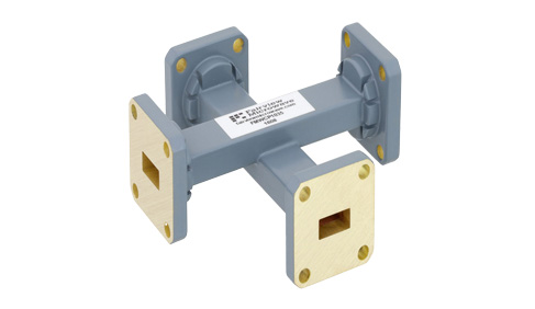
There are a variety of methods of constructing waveguide directional couplers. Some of these methods include Bethe-hole, multi-hole, magic-T, bi-directional/dual-directional couplers, and quad-couplers. The type of waveguide directional coupler dictates the coupling ratio, frequency range, directivity, power handling, and VSWR.
Waveguide Coupler Types
- Bethe-hole
- Multi-hole
- Magit-T (Magic Tee)
- Array
- Monitor
- Broadwall
- Directional
- Bi-directional/dual-directional
- Branchline
- Cross-guide
- Dual monitor
- Vestigial loop
- Quad couplers
- Hybrid couplers
- Single and multi-loop loop couplers
Another factor that impacts the frequency of these couplers is the waveguide size. Many waveguides are made using standard sizes that are compatible with standard waveguide flanges. These standard waveguide sizes have specified operating frequency ranges, including a minimum and maximum operating frequency of a specified dominant mode. The frequency range of the coupling structures could be the limiting factor in the operating frequency range of the waveguide directional couplers and be less than the specified bandwidth of the typical waveguide of that size.
In general, waveguide directional couplers outperform coaxial and planar circuit directional couplers in VSWR, directivity, return loss, power handling, voltage breakdown, insertion loss, and are often allow for more degrees of freedom and precision with coupling factor. However, waveguide directional couplers also have a larger footprint, much of which are dictated by necessary physical geometries and waveguide flange sizes. Some waveguide directional couplers have standard waveguide flanges for the main ports, but may use a coaxial port for either one or both of the coupled ports. As waveguide terminations tend to be higher performing than coaxial terminations in this case, if a single directional coupler is needed, it may be desirable to use a coaxial coupled port in conjunction with a waveguide termination for the other coupled port, as with the Waveguide Directional Coupler With Coaxial Coupled Port.
FAQs (Frequently Asked Questions)
Q1: What is a waveguide directional coupler?
A: A waveguide directional coupler is a passive device that samples a portion of RF power within a waveguide system without interrupting the main signal flow. It’s often used for monitoring and measurement applications at microwave and millimeter-wave frequencies.
Q2: How does a waveguide directional coupler differ from a power divider?
A: Directional couplers extract a small fraction of the signal in a specific direction (forward or reverse), whereas power dividers split power equally among ports. Couplers are mainly for sampling and monitoring, while power dividers are for equal distribution in signal paths.
Q3: Where are waveguide directional couplers commonly used?
A: They are used in radar systems, satellite communication links, wireless backhaul infrastructure, signal test benches, and RF power monitoring systems due to their precision and high-frequency performance.
