
What Are Dipole Antennas
Key Takeaways
- A dipole antenna consists of two identical conductive elements (rods or wires) fed at the centre; it does not require a separate ground plane like a monopole.
- The most common configuration is the center-fed half-wave dipole, where the total antenna length is roughly half the wavelength of the target frequency. This ensures efficient resonance and minimal return loss.
- Dipoles produce a “donut-shaped” radiation pattern: maximum radiation/performance perpendicular to the antenna axis, and nulls along the axis. This gives omnidirectional coverage in the horizontal plane.
- Variants such as folded dipoles or dipole arrays can offer wider bandwidth, higher gain, or adjusted impedance, making them versatile for broadcasting, communications, and other RF roles.
- Dipoles are widely used because they are simple to build, cost-effective, reliable, and well-understood, suitable for everything from simple wireless links to more complex RF and broadcast systems.
What Is a Dipole Antenna — Structure and Operating Principle
A dipole antenna is one of the simplest and most widely used RF antenna structures, consisting of two conductive elements of equal length connected to a feed point at the center. When an alternating current is applied at this feed point, the current flows into each arm, creating an oscillating electromagnetic field. As the current reverse direction with each RF cycle, the antenna radiates energy into free space. The classic half-wave dipole has a total length of approximately λ/2, making it naturally resonant at its design frequency and enabling efficient radiation with minimal return loss. This balanced structure does not require a ground plane, which distinguishes it from monopole antennas.
How a Dipole Radiates — Radiation Pattern, Resonance & Polarization
A dipole antenna radiates electromagnetic waves primarily perpendicular to its axis, producing a doughnut-shaped radiation pattern. When the dipole is mounted vertically, it provides omnidirectional coverage in the horizontal plane, ideal for communication systems requiring uniform reach. The antenna operates most efficiently at resonance, which occurs when its length is tuned to approximately half the wavelength. At resonance, impedance is well-behaved, radiation efficiency is high, and VSWR is minimized.
Dipoles are also linearly polarized, with the electric field aligned along the physical axis of the elements. This means a vertically oriented dipole produces vertical polarization, and a horizontal dipole creates horizontal polarization, critical for matching antenna orientation across a communication link to avoid cross-polarization losses.
Common Dipole Variants — Straight, Folded & Array Configurations
Beyond the basic straight half-wave dipole, several variants extend functionality for different RF environments. The folded dipole consists of two parallel conductors joined at the ends, offering higher input impedance and broader bandwidth commonly used in broadcasting and wideband applications. Shortened dipoles use loading techniques like coils or capacitive hats to maintain resonance when physical length must be reduced. Dipole arrays, such as collinear or stacked designs, combine multiple dipoles to increase gain and shape radiation patterns for long-range or directional communication.
A part of wireless communication and sensing are transducers that can convert free space waves into conducted signals that can be directed to and from RF circuits. These transducers, RF Antennas, come in many forms and geometries based on complex arrangements that balance frequency range, antenna pattern, gain, size, manufacturing complexity, and other practical considerations. RF antennas are divided into two main categories, omni-directional and directional antennas.
Omni-directional antennas have a roughly even 360-degree horizontal (azimuthal) antenna pattern that is generally not completely omni-directional in the vertical (elevation) antenna pattern. Directional antennas are any antenna type that has less than a 360-degree azimuth antenna pattern. These can range from just under omni-directional to an incredibly narrow antenna pattern that is similar to a focused beam, such as a parabolic dish.
One of the simplest and most common omni-directional antenna designs is the venerable Dipole Antenna. The practical realization of a dipole antenna, of all the antenna types, most accurately produces an antenna pattern like that of an ideal electric dipole. This pattern is based on a line current with nodes at each end of the dipole, which is constructed of two identical linear conductive elements aligned opposing each other. The electrical signal is injected into a dipole with each side of the feedline connected to the base of the two halves. This arrangement allows for a dipole to generate its own pseudo ground plane in between the opposing halves and eliminates the need for an external ground, as a monopole antenna does.
A dipole antenna can be as simple as two wires connected to a feedline, but may have more complex features, such as the “rabbit ear” style antenna used in broadcast television. Radar altimeters, sometimes made using a dipole antenna, are used by commercial airliners to determine altitude. In the case of a radar altimeter, the dipole would be oriented, so the radiation pattern is projected toward the ground before and beneath the airplane, where most wireless communication dipole antennas are oriented so the antenna pattern projects horizontally for maximum transmission range and coverage.
The relative length of the dipole ends in relation to the wavelength of the desired center frequency impacts the performance of the antenna. Dipole antennas are also often used as drive elements for more complex antennas, such as Yagi Uda antennas. By adding additional conductive structures around the Dipole, generally attached to the ends, the bandwidth of a Dipole antenna can be extended among other performance modifications.
Frequently Asked Questions (FAQ)
Q1: What exactly is a dipole antenna?
A: A dipole antenna is one of the simplest types of RF antennas. It consists of two identical conductive elements (rods or wires) arranged end-to-end and fed at the center. When driven by an alternating current, it radiates electromagnetic waves into space.
Q2: Why is the half-wave dipole the most common form?
A: A half-wave dipole is resonant at a frequency where the total antenna length equals approximately half the wavelength (λ/2). This resonance ensures efficient radiation, good impedance matching (~73 Ω in free space), and minimal reflected power.
Q3: What does the radiation pattern of a dipole look like?
A: A dipole antenna radiates strongest in the plane perpendicular to its axis, producing a doughnut-shaped pattern. This means maximum energy is radiated horizontally (if the dipole is vertical), while radiation along the axis (up or down) is minimal.
Related articles
Peter McNeil | Oct 25, 2022 | Antennas
There are a wide range of antenna technologies available today. A more recent option is to choose a multi-input multi-output (MIMO) antenna. Though newer, is a MIMO antenna better than a traditional single-input single-output SISO antenna? More is always better right? This is certainly not the case with SISO and MIMO antennas, and like virtually every RF circuit/signal chain, the antenna is a critical component that needs to be precisely specified for a given application and that decision making needs to include the other devices/components in the system.
A SISO antenna is a single-port antenna that has a single driven element, though the antenna could be balanced or unbalanced depending on the design. A MIMO antenna, on the other hand, is an antenna system that consists of at least two distinct antennas. Each of the MIMO antenna elements has a distinct input port that is designed to be driven individually from a MIMO compatible radio. In theory, a MIMO antenna may be driven like a SISO antenna by splitting the power from a SISO radio to the multiple MIMO antenna elements. However, this likely won’t provide substantial benefit, and an appropriate SISO antenna would probably provide better performance, especially considering the intrinsic losses associated with introducing any passive elements in a signal chain.
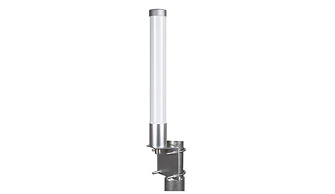
SISO Omni Antenna
In order to make the most of a MIMO antenna, a MIMO radio is needed. This could be a WiFi or cellular system that makes use of MIMO technology and spatial multiplexing to provide higher throughput than is possible with a single spatial channel.
The number of MIMO channels, radio hardware/protocol, and channel quality determines the overall throughput gain possible compared to a SISO antenna system. If the radio hardware/protocol or channel quality is poor, then a MIMO system may not provide any substantial benefit over a SISO system. Hence, knowledge of the channel and radio technology are critical in determining if a MIMO antenna is appropriate. If the application is appropriate and the communication link is between two MIMO-equipped nodes, then it is possible to achieve many times the throughput of a comparable SISO communication link. It is important to note that MIMO isn’t necessarily using different frequency bands to increase throughput but is instead using spatial multiplexing to create separate spatial channels with their own communication stream.
Generally, the only reason to employ a MIMO system is to provide greater throughput, possibly to a larger number of devices in a given region. MIMO systems are intrinsically different and should not be confused with beamforming antenna systems, though an advanced antenna system (AAS) may be both MIMO and beamforming capable.
Peter McNeil | Feb 02, 2026 | Antennas
A Yagi-Uda Antenna (Yagi Antenna), named after the co-inventors Hidetsugu Yagi and Shintaro Uda, is a direction antenna with a single driven dipole section with a series of parasitic elements (directors) that re-radiate energy from the main dipole thus manipulating the antenna pattern. The parasitic elements of a Yagi antenna are within the near field of the main dipole, and hence significantly alter the antenna pattern as compared to a dipole without parasitic elements. The overall effect results in a much more directional antenna pattern, with the antenna pattern being dedicated by the spacing and length of the main dipole and parasitic elements.
Key Takeaways
A Yagi-Uda antenna uses a driven element plus parasitic elements (reflector and directors) to focus radio energy in a chosen direction. The reflector boosts forward gain by suppressing backward radiation, and directors further narrow the beam and increase forward gain.
Each additional director contributes diminishing returns in gain increase. High-gain Yagis tend to have narrow bandwidth, require precise element spacing and mechanical support, and often need impedance matching for proper feedline connection.
The front-to-back ratio is an important metric for interference rejection, but designing for a high F/B ratio may conflict with maximizing forward gain or bandwidth. Yagi antennas excel in fixed, directional, and narrowband scenarios such as point-to-point links, rural connectivity, broadcast reception, and amateur radio.
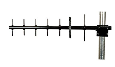
What Is a Yagi-Uda Antenna
A Yagi-Uda antenna (commonly called a Yagi) is a directional antenna that uses a driven dipole element plus a set of parasitic elements (a reflector and one or more directors) to shape its radiation pattern. The parasitic elements are not electrically connected to the feedline. Instead, they receive energy from the driven element and re-radiate it in controlled ways so that radiation in one direction is reinforced and radiation in other directions is canceled or reduced. This arrangement transforms an omnidirectional dipole-like pattern into a directional beam.
How the Number of Elements Affects Yagi Performance
Increasing the number of parasitic elements directly influences the Yagi’s gain, directivity, and beamwidth. More directors generally lead to higher forward gain and a narrower radiation pattern, making the antenna more directional.
Impact on Gain and Beamwidth
Each additional director typically adds a small amount of forward gain—usually around 0.5 to 1 dB—while also narrowing the beamwidth. This increases the antenna’s ability to focus energy and reject signals from undesired angles.
Diminishing Returns with Additional Directors
After a certain point, adding more directors yields minimal gains and improvements while increasing mechanical complexity. Beyond roughly 10–15 elements, physical size grows significantly, but performance improvements become marginal.
Directional Yagi Antenna
Yagi Antennas are a type of fixed antenna and are often mounted on a mast or pole and can be used indoors or outdoors depending on their IP rating. Some examples of Yagi Antennas include the FMANLP1005 Yagi Antenna which operates in the 5 GHz band to provides highly focused directional connectivity. The FMANLP1010 Yagi Antenna offers 14 dBi of gain along with vertical polarization and operates in the 3 GHz band to address 5G, LTE, CMDA, LoRA, IoT, WIFI applications.
A Yagi antenna also typically has a reflector section positioned “behind” the driven dipole element to further aid in increasing the directivity of the antenna. The reflector is often a series of conductive shafts, or mesh, typically about 5% longer than the driven element, and can consist of one or more shafts spaced “behind” the driven element. The reflector may also wrap around the “sides” or “top” and “bottom” of the Yagi antenna to further concentrate the antenna radiation in the forward direction.
The impact of the reflector is to increase the gain in the forward direction by reducing the radiation in the reverse direction of the antenna and focusing that radiation instead in the forward direction of the antenna (adds around 4 or 5 dB of gain to the forward direction. Though careful design can largely reduce sidelobe development, sidelobes are still developed that reduce the overall gain of the Yagi antenna.
The directors also add gain in the forward direction, by capturing and re-radiating the radiation that would otherwise spread out in a dipole antenna pattern. In this way, the Yagi antenna gain is a function of the number of directors added to the front of the antenna. There is a point at which the benefit to gain of designing in additional direction begins to diminish, with a maximum Yagi antenna gain limited to around 20 dB for a single antenna. By adding more directors the beamwidth of the Yagi antenna narrows along with increasing gain, which results in a practical limit for certain applications.
Moreover, the spacing and size of the Yagi antenna directors and mechanical structure to support the antenna structure results in a practical limit for the gain and directivity of low frequency Yagi antennas. This is due to the larger spacing and director lengths needed for efficient operation at lower frequencies. Hence, high gain Yagi antennas with high directivity are also naturally long antennas. A common figure-of-merit for a Yagi-Uda antenna is the front-to-back ratio. This is simply a ratio of the antenna radiation in the forward direction of the antenna and the reverse direction of the antenna, often expressed in a log ratio (dB).
The bandwidth of a Yagi antenna is also a function of the size of the Yagi antenna, namely the length, diameter, and spacing of the elements. Yagi antennas typically have a maximum percent bandwidth that is a few percent of the designed center frequency. The number of elements also reduces the bandwidth of a Yagi antenna, so a higher gain Yagi antenna also has a narrower bandwidth along with higher directivity. Therefore, when designing a Yagi-Uda antenna, there are generally trade-offs with the key performance parameters of gain/directivity, frequency of operation, bandwidth, size, and front-to-back ratio.
Explore our wide range of RF Antennas.
FAQs (Frequently Asked Questions)
Q1: What makes a Yagi antenna directional?
A: The driven element works with parasitic elements that reradiate energy in a way that reinforces forward radiation and reduces backward energy.
Q2: How does the front-to-back ratio affect performance?
A: A higher ratio improves rejection of interference coming from behind the antenna, which is useful for crowded RF environments.
Q3: How many directors should a Yagi have?
A: Adding more directors increases the gain but with diminishing improvement. Practical designs balance gain with mechanical size and bandwidth.